Monday, January 30, 2012

Electronics Lessons: The Relay Simple Circuits (burglar alarm)

Now that the festive season is over, and I've got a little more time I hope to start posting a few more electronics and craft lessons, and some more look what I did projects, rather than the code lessons, which are pretty dry and uninspiring to write at the moment.

Another thing about the festive season is that assuming you were lucky you probably have a whole load of new stuff.

Obviously you like your new stuff, and don't want to loose your new stuff, so we'll look at some protection systems for your stuff.

An absolute classic of beginner electronics, A burglar alarm.

We start with a fairly circuit, it looks a bit like the amplifier that was made sometime last year, except instead of a resistor there's a switch in the circuit, the switch is the kind that you'd put on a window or door frame to detect entry.


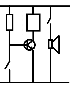
We see that in standby mode the normally closed switch grounds the base of the transistor meaning that it is in the cut-off region and does not conduct.
As the transistor is not conducting the relay is not energised and the buzzer does not sound.
Now some one comes and opens the window. now the base of the transistor in not grounded and instead is at a high level, the transistor now begins conducting and the relay is energised, causing the buzzer to sound.


Latching

The trouble with the circuit above is that as soon as the would be burglar closes the window (maybe with them on the inside) the transistor is grounded again, and so stops conducting and therefore the relay and buzzer go off.

What we need is a way of turning on the relay and having it stay on.
the term for this is having the relay latch on.

It is possible to get relays that latch automatically, but these tend to be expensive, so we're now going to show how we can turn a regular relay with two switches in it. (double pole)

What we do is place one of the switches in parallel with the collector and emitter connections on the transistor.


Now when the transistor turn on electricity flows energising the relay, when the relay is energised the switches inside close adding another path that the electricity energising the relay can travel through.

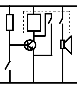
When the window switch closes again the transistor stops conducting but the closed contact in the relay doesn't, and because this path still exists the relay is energised so the alarm stays on.

To reset the circuit all you need to do is momentarily break the power going to the relay then the contacts will open and there would be no path to energise the relay so the alarm stops also.

Monday, January 23, 2012

Fixing an amplifier 2

Though the article is called fixing an amplifier 2, that's because this is the second time that I've been asked to fix an amplifier by a friend, note it's a different amplifier, the first amplifier fix was good and it's still working.

So, what's actually wrong with this amplifier.

Well, the amplifier is a fender blues junior. these are some (in my opinion) very neat little amps, they have a kind of classic warm blues sound to them, they sound great when they are played at a medium level with a lovely clear signal thought them. They don't do that rocking blues, but they do clean blues sounds really well.


It's come into my hands because the reverb circuit appears to have stopped working.

One of the very cool things about this amplifier from a yes you can fix it point of view is that the circuit diagram actually comes with the amplifier, a quick look at the circuit shows that it's a fairly straight forward reverb circuit.

The signal splits after the pre-amp, and there is a clean channel and a reverb channel, the reverb channel goes to the reverb tank, then after the reverb tank comes back to a recovery amp, then into a mixer circuit where the time delayed signal is mixed to the clean signal to create reverb.

So the first place to look logically is the first component in the circuit.

The reverb tank.
in a guitar amplifier is is most usual to find spring reverb units. the unit works like this.

at the start of the reverb there is an electromagnet, the audio signal goes through the coil of the electromagnet.

that creates a magnetic field that varies in strength according to the music.

the electromagnet acts to move a spring.
the movement at one end of the spring travels through the spring to the other end, where the the springs are contained in wraps of wire.
the spring induces a current in these wraps of wire, (moving magnetic material in a fixed coil induces electricity).

that very small induced electronic signal is then amplifier and mixed back into the original circuit.

the springs work because they are metal and thus conduct the magnetism applied to them as well as the vibration incurred as the coil is energised with the musical signal, in a straight wire this may introduce delay, but the springs, (being as they are springy) bounce around, even after the original signal is recovered the springs will still be bouncing, eventually (as the springs are under tension) the transmission springs movements dampen down until they stop.

It's this dampening that causes the multiple echo sounds that we call reverb.

Back to the amp
In order to test the reverb tank you will need a multimeter.

First unplug the round connector that is at the input side of the tank, and measure the resistivity of the reverb tank, (connect one probe to the centre of the connection, the other probe to the outside.

Make a note of the resistance.

Next unplug the connector on the output side of the reverb tank and measure this.

These reading should be reasonably low. I can't remember off the top of my head what they should be, but one side was reading quite low, not so low that it seemed like it might be shorting out.
The output side was reading very very high, so high that it was likely that there was a break in the coil.

I ordered a reverb tank on-line and replaced the tank. and this amplifier started working again.

30 minutes, and taking out four screws was all it took to fix this amplifier.

Monday, January 16, 2012

Coding Lessons: C and pointers (lesson 14)

In the lessons last year we looked at a the basic variables in C, integers, longs, floats, chars, short integers, arrays or chars and strings (which are just null terminated arrays of chars).

What we didn't think about is what's going on inside the device.

This gets confusing quickly.

so lets try and take things slowly.

Lets declare a variable.

int num;

We've declared a variable we called that variable num, we say that variable will be an integer number.

Behind the scenes what has happened is that the program that we write will take a section of memory that is the size of an integer, (remember from lesson 2 int is 32bit numbers) so a section of memory, (a box) is set-up, that will contain the data than we assign to num.

The box is called num, we can put number data into that box.

num = 23;

Now the box called num has the data 23 in it.

But there is something missing from this whole idea: where is the box?

The box is "somewhere" in memory, it has an address.


So now lets declare a new variable

int *mem_ptr = #

now this is a strange one, first, what's that star all about, and second, how are we putting the string &num into an integer variable?!

Well, firstly, the star specifies that this is a pointer, it's going to point to a memory address.

what comes next is a little weird and interesting.
we're not butting a string into the box we're telling it, that pointer, points to the address of the variable num, that & symbol is the address operator.


so let's look at this in a program.

#include <stdio.h>
int main()
{
int num;
int *mem_ptr = &num;

num = 8;

printf("num = %d\r\nptr = %d\r\n", num, *mem_ptr);

}


When you run this program you get the following output:

D:\coding\lesson14>tcc source.c

D:\coding\lesson14>source.exe
num = 8
ptr = 8


which is pretty obvious.

you're writing, Make a variable called num, that's an integer.
but what you're really saying is go get me 32 bits of memory, I want to store something, I'll refer to it as num...

So then when you use the pointer and say, the pointer has the same value as the address of the variable num (it looks at the same memory location) of course the value is the same, it's looking at the same 32 bits of memory,

as well as looking at the variable by inspecting the same memory location, we can also, write to memory by writing to the memory address that the variable uses by writing to the pointer to that memory address.

#include <stdio.h>
int main()
{
int num;
int *mem_ptr = &num;
num = 8;
printf("num = %d\r\nptr = %d\r\n", num, *mem_ptr);
*mem_ptr = 1;
printf("num = %d\r\nptr = %d\r\n", num, *mem_ptr);
}


D:\coding\lesson14>source.exe
num = 8
ptr = 8
num = 1
ptr = 1


we can also change the memory address that the pointer looks at during the program.

in the following source code we'll set up two variables, one called num and the other called digit, then tell the pointer to look at the contents of the address space given to num, (and we'll compare that to num) then we'll look at the contents of the address space given to digit to show how the pointer can move.

#include <stdio.h>
int main()
{
int num, digit;
int *mem_ptr = &num;
num = 8;
digit = 9;
printf("num = %d\r\nptr = %d\r\n", num, *mem_ptr);
mem_ptr = &digit;
printf("num = %d\r\nptr = %d\r\n", num, *mem_ptr);
}>


D:\coding\lesson14>source.exe
num = 8
ptr = 8
num = 8
ptr = 9


Types of pointer.
We're comfortable that a pointer looks to a memory location, and that can be changed.
so far out pointer

Monday, January 09, 2012

Electronics Lessons: What is Modulation?

It occurs to me that a few lessons back I introduced Pulse width modulation. then I did a second lesson and described some further uses for pulse width modulation.

but I missed out something pretty fundamental.

What on earth is modulation?

Modulation is a way of transmitting information using another medium.
another medium in controlled in such a way that information is then contained on that medium.

If you consider a piece of fibre optic glass, in those little fibre optic Christmas trees it's just light you see, but if you turn that light on and off really fast, or very the intensity of that light then you are modulating that light. if you do it in a set pattern then you are modulating information onto that light.

When talking about modulation you must always think that there is an encoder segment to the system, and a decoder.

When you think of radio, the radio station has the encoder, where they modulate the data onto a radio wave, this modulated wave is the send to the transmitter.The modulated radio wave is then received by your antenna, and the circuit goes to your receiver when it is demodulated.


The simplest form of modulation when thinking of radio is AM, that is amplitude modulation of a radio wave.

This is the simplest type of modulation to create, and the simplest type to receive and demodulate also.

AM Modulation
You start with two wave forms, we're thinking of radio right now so we're thinking of audio data, but it could just as easily be digital data.
The first wave form is your audio/data wave form, in this example this is a sine wave.

The second wave form is your radio frequency wave, this has a frequency much greater than your audio waveform.


The first part is the encoding, what we do here is alter the amplitude of the radio wave such that the radio wave now looks a bit like the audio wave.

You can see that the radio frequency wave now has the basic shape or envelope of the audio wave.


This is the wave that it transmitted from the radio tower. This is the wave that is received by your radio.


After receiving the broadcast signal the first thins that your radio receiver will do is "chop" out half the signal so that only the positive half cycles of the broadcast signal remain.


Then the radio will filter out the higher frequency radio waves leaving only the audio waves.

You can now see how data of a very very very low frequency, (Audio) can be transmitted using a much higher radio wave frequency. received and decoded from the carrier wave. the carrier wave that has been modulated.


So back to the original topic at hand, Modulation.
Modulation is a term used to describe the changing of the characteristics of a waveform in order to impart or modulate information onto that wave form.

The above example looked at amplitude modulation.

Another popular radio modulation scheme is frequency modulation.

FM Modulation

For frequency modulation the frequency of the carrier wave is altered depending on the information modulated onto it.

Looking at the audio wave, as the audio wave rises the frequency modulated radio wave increases, as the audio wave descends into a trough the frequency of the modulated radio carrier wave decreases.

PWM
A form of modulation that I discussed before was Pulse width modulation, here audio data in imparted as pulses in a signal.
so in the case of the audio signal above, as the information wave form peaks, the pulse widths increase, as the wave falls the pulse widths decrease.

Monday, January 02, 2012

2011 Post Index

Happy New Year

I thought I'd start the year with a look back at the year just gone.

For the start of the year I did nothing with this blog, (pretty much as I had done nothing for years). Then I was browsing the hackaday site, and decided that I really should actually use my blog, my blog was first created as a way for me to express the projects that I was doing at the time. to write them down and share them.

I realised that I would be unable to make a blog purely about the projects I do, (because I don't do enough) also that a lot of the time it's not the project that matters to people trying to do things, it's the how it gets done, and the how to do it yourself.
If I just show you how I did something, but don't tell you how I got there then without having the same experiance as me then how do you know how to get there. I was bored of reading projects and thinking it's nice that they got that, but how did they get that? So I decided that I'd make a big feature of my blog a learnign experiance, telling people how things work, and why things work, building up knowledge and using that knowledge.

So, now that it's 2012, I thought I'd post a quick round up of 2011.

Projects
Starting with the projects, (I've not documented nearly as many projects as I'd have liked!)
Red light torch for reading maps at night
Cheap bench power supply from an ATX supply
Home Built HiFi speakers
Logic Level indicator
Improving home efficiency with insulation
Making a light bulb oil lamp
Fixing a guitar practice amp
Changing kitchen or bathroom blinds

Opinions
I've written a couple of opinion pieces, not in that traditional this is what I think of this kind of way, but opinion as to what I believe are basic essentials, essentially I use the term opinion piece to say something you could argue with:
What you should buy first for your electronics hobby
What you should buy first for your woodworking hobby
More advanced tools that you should consider as your hobby progresses

Craft Lessons
I've produced two craft lessons to demonstrate technique, generally I'm using the craft lessons to demonstrate a more generic way of doing something that I've used in a specific project.
Jointing wood
How to French Polish

Electronics Lessons
I've made a series of electronics lessons with the aim of introducing the components, and the theory and technique behind them, I'm aware that these lessons can be a little dry and a little theory heavy if you're just starting out. DO NOT let that put you off.

If you're a student learning, or wanting to learn in a formal manner then I've tried to gear the lessons in this way. on the other hand if you don't care, and just wanted a short sweet overview I've tried to break up the lessons so that at the start in depth theory can just be skipped over.

Resistors, Ohms Law
Diodes
Simple Output devices
Resistors
Capacitors
Transistors
Light Emitting Diodes
Using Transistors
More uses for transistors
Even more about Resistors
Using Capacitors
Switches
All about Wire
Breadboarding circuits
How to make an amplifier
Pulse Width Modulation
Relays
Relays and EMF
More Uses for Pulse Width Modulation

Coding Lessons

And finally I've written 13 lessons on beginning to make programs using C on a computer, the plan moving forward for these lessons is to take the code away from a computer and run on an embedded system (such as an arduino or a PIC chip. I've some experience of Motorola 68HC11, Microchip PIC series, and Atmel AVR series chips, so I'm intending to keep these lessons as portable as possible, meaning that you can take the lessons learned and (in most cases) use different compilers, different platform architectures. and where the bits are not compatible, (for example a library doesn't exist for your compiler) the idea is that you'd be able to write your own.
Later on I'll also go into using Assembler for programming micro controllers.

Hello World
Variables
More Variables
Inputs
Getting more data in
Body mass index calculator
Introducing Functions
Including other files
Arrays
Strings
Conditions in programs
Loops
Using and manipulating Strings

And that's it for 2011, so onwards and upwards, I plan to write updates at around 1 per week. I started off with great gusto writing three posts per week, but since then I've realised I don't have the time to keep up that output. and the quality of the posts, lessons and write ups suffers when I try to do so much.