Showing posts with label audio. Show all posts

Monday, July 02, 2012

Fixing an Amplifier 3

Fixing an Amplifier: 3

So that Fender Blues junior amplifier has come back under my nose, and it has a very weird problem.

Altering the volume knob makes it sound like it's tuning a long wave radio.

it whistles and hums, you can modulate the whistling sound bu altering the volume and tone.
something is definitely not right.


Trouble shooting.
So the first thing to do it try to figure out what's wrong.
Clearly there is something unstable and oscillating inside the amplifier, and this is causing random and weird noises to be picked up and generated.


So first, I take the back off.
have a cursory glance for anything loose or disconnected.
I can't find anything.

I plug the amplifier in and see if anything looks a little out of place, or weird.
the humming starts again, (notice the humming is worse because the main board is no longer completely shielded.)

Lightly touching the ribbon cables that connect the main board to the valve board produces interference, it seems that the low voltage signal going into these boards is particularly susceptible to interference.

In order to reduce this problem the ribbon that carries the instrument signal to the pre-amp valve, and the ribon cable to the valve used after the reverb recovery amplifier are shielded in aluminium foil.


The amplifier now has slightly less interference, but when adjusting the volume the weird noise (though not as pronounced) is still there.


Now I begin inspecting the circuit diagram in detail.
It seems that there is not really a lot to go wrong in these amplifiers, in fact the only thing that can go wrong is, Valves break, reverb recovery amp any break (but very unlikely without excessive abuse) and electrolytic capacitors leak.

I looked long and hard at every electrolytic capacity on the board, and found that one of the four large grey filtering capacitors was slightly deformed.

Searching on-line led me to find that what appears to have happened is, in some inane bid to save money, Fender bought the cheapest sub par quality components that they could find. there are loads of stories of these leaking, and bulging and stopping amplifiers working.

So I ordered some more capacitors and changed these for new (and better quality) ones.


the amplifier is now working perfectly again.

I have left the foil shielding on the ribbon cables, this adds a slight capacitance to the circuit and rolls off the brightness of the amplifier slightly.


Monday, June 18, 2012

Carputer

Once upon a time I had a particularly rubbish car. actually the car was great fun to drive, and never really broke down it was as basic as you could get.

the stereo was also basic, but it had an audio jack socket on the front. and I had something called an Mstation, this is a large hard disk MPs player, with an LCD screen that shows the tracks playing etc.

Then I got a new car, there was no where to mount my Mstation, but I had a cd changer (rather than just a player)

And then that wasn't enough.
so I got a PureDAB digital radio, but the reception was rubbish.

But what it did have was a audio input jack socket.

I decided that rather than re-use my Mstation (which I'd still have to mount and find a way to get to the controls cleanly, I wanted something invisible.

That is when I decided that my car should have a computer in it.


Now this isn't the standard car-puter build, I've already made it reasonably clear that I don't want to cut holes in my dashboard (else I'd just use the Mstation).

and I want this to be as hidden as possible.

and that's when it hit me.

I'd use a computer and use my phone as the control unit.

I also knew I would never want to take the computer or hard disk out of the car, I'd want to be able to pull up to my house and access the computer via my standard home network


Computer
The computer had to be something that would not loose power.
I had an old laptop that was not being put to use so I decided that I would use this.
being a laptop it came with it's own power supply that could keep it running even when the car was off, (when I parked up outside my house)

Software
For simplicity, because it offers an "out the box" solution I decided that I would use Itunes, with the itunes remote application on my phone being used to alter the volume and to skip tracks, where the phone could sit in a regular phone holder as I drove.

Storage
The computer had a relatively small hard drive, so storage will be a small USB powered external hard drive

Connectivity
The iphone does not like non-infrastructure networks, and besides, I want the laptop to connect to my home network, so it can't be trying to be an infrastructure network
To accomplish this, the wireless network of the latptop would be set to autheticate on my home network. now whenever I drive near to my house the computer will recognise the network and connect to it.

The wired connection on the computer will connect to a wireless access point which will server a localised network (called pugnet as my car is a peugeot) this is the network that my iphone will connect to, allowing itunes remote to connect to the itunes software for control.

Power
The power for the laptop will be provided by a shop bought in car laptop power supply. the power for the WAP (9v) will be provided from the cars 12volt electronics and be regulated with a 2a LM7809 voltage regulator.

Mounting.
The front squab of my passenger seat lifts up to reveal a little storage compartment, the computer will sit under the seat in the front of the car, hidden from passing eyes,

All the fiddly electronics bits are build into a wooden box that sits in the bottom of the compartment,
the laptop sits on top.


How it all works.
I leave my house in the morning, and get in my car.
when I turn my car on, the laptop receives power and ideally boots up (no worries if it doesn't). additionally the wireless access point turns on.
as I drive down the road my iphone looses connectivity to my home network, but finds the car network pugnet and authenticates on this network.
if the computer has not started I use a free application on the iphone called NetAwake to send a packet to the computer requesting that it wakes up (wake on LAN is enabled on this laptop)
the computer turns on and boots, Itunes is in the startup folder and so automatically starts.

When I start the itunes remote application it searches the network for itunes servers, and finds the laptop.

I press play, the laptop plays songs (from the USB hard drive) through the laptops external audio connection, which connects to mu PureDAB highway radio, which transmits via FM to my stereo, and plays through all the speakers.


When I get home...
the laptop discovers my home network and connects
I turn off the car, this immediately kills the power to the access point (which turns off) and kills power to the laptop. -the laptop remains on powered by battery power.

I go inside.
start my regular computer, where I can use VNC to connect to the car laptop and update the itunes library with songs that I can just drag and drop wirelessly into my car!

until the laptop battery runs out. at which point windows knows that it's low on battery power and gracefully shuts down the machine.

Monday, June 11, 2012

Electronics lessons: Music effects: The distortion pedal

This is the first guitar pedal that I eve made...

What is distortion.
Distortion is the changing of a wave form from one form to another so as to distort it.

Technically speaking, a tone control distorts the signal, a envelop filter distorts the signal, anything that "colours" the signal also distorts it.

but if I stop being a smart ass for a second.

distortion to most people means fuzz.

History of overdrive.
It seems to make sense to me to start at the very beginning, and lets take a look at the physics of what's happening.

Many people try to make a distinction of what type of distortion they are listening to, if it's a hard clipping, or soft clipping, some people thing that an over drive and a distortion are different, they kind of are, but fundamentally it's all the same.

OK, distortion was around long before this, but lets set the scene...
To understand this analogy you;re going to need to know what a green back is.
A green back is a speaker made by the British speaker manufacturing company Celestion in the 60's or 70's.
It was a basic run of the mill speaker, which has gained cult status (and price) with it's inability to handle the power of the signals that people were trying to drive thought it.

Now you might think that from the description above of a basic speaker that's gained notoriety for sounding bad might make you think that I dislike it.
nothing could be further from the truth. the point I'm getting at here is that the magic sound of 60/70 British rock, (think Rolling stones/Yard birds/Led Zepplin) lays a lot in the mechanical and electrical limitations of the time.

Consider how a speaker works,
a coil of wire is suspended in a permanent magnet,
the coil of wire is subject to an electrical current, this makes the coil magnetic, where it will be either attracted to, or repelled from the permanent basket on the back of the cone.
the coil has a paper cone attached to it.
as the coil moves the paper cone moves, this moves air particles, which vibrate through the air and then the air vibrates against our ear drums and happy days we hear sound.

So we get that the coil is moving, and we get that we can turn the volume up and make it move more, but, the coil is attached (with what's called suspension) to the metal frame (spider) in the speaker construction. The size and stiffness of the suspension limits how far that speaker cone can move.
that means that for very large wave forms the speaker will not replicate exactly what is being asked of it.
it tries to reach the point where the signal applied it telling it to go, but excersion limits are met and the speaker cannot move any more.
additionally the suspension on the speaker slows down the cone as it reaches the excursion limit

So the following picture hopes to show you what I mean, I've drawn it on it's side so you can visualise a speaker cone going in and out.

The thick black line is zero, this is where the speaker normally rests.
the red line is the input to the speaker.
you see it rising, the green line (speaker position) moves with it, then we reach the blue line, this is nearing the excursion limits for the speaker, so whilst the red line continues to move, the green line is being slowed by the suspension of the speaker.

The red line continues to rise where it meets the black line, this is the excursion limit the speaker can no longer move at all past this point whilst the red line continues to be at this point the speaker sits as it's maximum excursion position waiting for the red line to fall.

This is, in the most traditional sense an over drive distortion.
the wave is quite smooth, (as the suspension prevents square edges to the sound wave) and as such will sound like a warm fuzz.

It is also possible to get over drive distortion from an amplifier.
Consider the following chart.
the blue wave is what we want. the red wave is what we get

lets say we have an amplifier with supply rails of +15 and -15 volts, you we give the amplifier a 1v / -1v signal and say, amplify that, and set the gain to 15.

What should come out of the amplifier is a smooth wave (the same as went in) with peak values of + and - 15 volts.
but we can't actually drive the amplifier to the supply rail voltages, the most that we could get out is +13 and -13 volts, so the top and the bottom of the votlage is cut off.

This is a much harder clipping sound.

Now that we've listened to loads of music and realised that the classic hot sound of the 60/70s is so desirable what can we do to emulate that?
(clearly we don't want to run our amplifier at that level forever, and the amount of power that you need to put into a speaker cone to reach cone excursion limits makes your show loud, (and perhaps not suited to the venue size you have!)

So you want to fake it.


Well, now that we know what we're trying to fake, it's a very simple matter of finding a way to cut a little from the top and a little from the bottom of an audio wave.


So what we want to do is take a small wave form say 1 or 2 volts then shave a small amount of voltage off of it.

So what we want is a component that can give a low resistivity for small signals, and gradually that resistivity will increase until it hits a limit then it will only allow that amount of signal to pass.
kind of like some kind of flow control.


well, we don't exactly want flow control, but if we look at the diode we have the component that we need.

the following graph shows the voltage and current flow of a regular silicone an germanium diodes as they approach their forward conduction zones:

You see that (especially with the silicone diode) there is a gently slope on the voltage vs current graph, this is that component gradually decreasing it's resistance to a signal, until it reaches ~0.65 volts where it begins to conduct, at 0.7 volts the junction inside the diode is saturated and it's in full conduction mode.


So what does this mean for our distortion effect.

Well, quite simply, we wanted a component that we could use to clamp our voltage inside an artificial set of parameters that would mimic the gentle slowing due to suspension and then flat constraint of an over driven speaker. and with a diode we actually have that.


There are two ways of using diodes in a distortion circuit, these are often called hard and soft distortions.
what makes a distortion hard is very angular edges on the wave form when it flattens off, (see the picture of the amplifier distortion above, and soft distortion is more controlled, the distortion still exists, but it's smoother.

not only does the wave look smoother, but it sounds smoother too!.

There are two ways to use diodes to produce this distortion.

First we need to understand the building block that we're using.

two diodes are placed back to back, (and front to front)
this looks like a crazy way to put a diode,-surely they'll just conduct to ground regardless of the signal applied and there will be no output?

Well, no they won't just conduct to ground because as explained above, as the diode is switching on it has a resistance, and even when it's on there is a voltage drop.

So what actually happens is we clamp the signal line to only permit signals within a certain threshold, and limit any larger signals to that threshold.

So now we have a simple model.

for signals under 0.5 volts a diode acts much like an open circuit,
for (silicone) 0.5 - 0.7 volts a diode acts like a resistor with progressively less resistance being applied as the signal rises
for germanium diodes 0.2-0.3 volts acts like a resistor with progressively less resistance being applied as the signal rises
for signal over 0.7 volts the diode acts like a short circuit grounding the circuits and therefore clamping the signal to the activation energy threshold.


now that we have this component block figured out we can look at how to apply to to a circuit.

The first method of connection is to follow the amplifier that is used in the circuit with the component block.

This literally clamps the output to 0.7v, this type of circuit arrangement is suited to either Light emitting diodes or germanium diodes.
the use of silicone diodes produces a quiet hard clipping in this position, mixing a silicone diode and a germanium diode in series for the block can have a positive effect in making this clipping less harsh.


The second way to use this component block is in the feed back network of the inverting amplifier.

we put the network in parallel with the feedback resistor.

At low signals the diodes act like an infinitely large resistor.

so the value of 1/Rfn = 1/Rf + 1/diodeR(infinity) therefore the total value for the resistor network (Rfn) equals Rf

so if R1 = 100 Ohm, and Rf = 200 Ohms,
Gain = -Rf / R1 so the gain = 2

now as the signal gets larger the amplifier will put out a larger signal, when the output of the amplifier reached 0.55v the diodes are behaving like a resistor.
we'll (for the sake of simplicity) say that the value of this acting resistor is 200 Ohms.

now the feedback network has a resistivity if found by the equation
1/Rfn =  (1/200) + (1/200)
so Rfn = 100 Ohms

now the gain of the amplifier is
Gain =-rf/R1
gain = -100 / 100 = -1

so the gain has gone down.

Now the voltage continues to rise to above 0.7 volts, the diodes now act like short circuits.

the resistance of the feed back network a 1/Rfn = 1/200 + 1/0  so Rfn 0

and the gain is
-0/100 which also equals zero.

Remember a gain of 1 is unity.
the output = input x gain.

so a gain of zero actually turns the output off completely.
(but if that were to actually happen the there would be no voltage so the diodes would have infinite resistance again.

thus the voltage is again clamped in the region of the diode conduction threshold.


You can see in the graph below what a gradually increasing waveform looks like as it approaches the clipping region.
at the start there is no distortion, as teh wave gets gradually larger the clamping effect of the distortion begins to take effect, you see by the end of the graph the distortion is no longer smooth, the input signal is massive and the clipping is more and more choppy (and will sound worse)


Monday, January 23, 2012

Fixing an amplifier 2

Though the article is called fixing an amplifier 2, that's because this is the second time that I've been asked to fix an amplifier by a friend, note it's a different amplifier, the first amplifier fix was good and it's still working.

So, what's actually wrong with this amplifier.

Well, the amplifier is a fender blues junior. these are some (in my opinion) very neat little amps, they have a kind of classic warm blues sound to them, they sound great when they are played at a medium level with a lovely clear signal thought them. They don't do that rocking blues, but they do clean blues sounds really well.

It's come into my hands because the reverb circuit appears to have stopped working.

One of the very cool things about this amplifier from a yes you can fix it point of view is that the circuit diagram actually comes with the amplifier, a quick look at the circuit shows that it's a fairly straight forward reverb circuit.

The signal splits after the pre-amp, and there is a clean channel and a reverb channel, the reverb channel goes to the reverb tank, then after the reverb tank comes back to a recovery amp, then into a mixer circuit where the time delayed signal is mixed to the clean signal to create reverb.

So the first place to look logically is the first component in the circuit.

The reverb tank.
in a guitar amplifier is is most usual to find spring reverb units. the unit works like this.

at the start of the reverb there is an electromagnet, the audio signal goes through the coil of the electromagnet.

that creates a magnetic field that varies in strength according to the music.

the electromagnet acts to move a spring.
the movement at one end of the spring travels through the spring to the other end, where the the springs are contained in wraps of wire.
the spring induces a current in these wraps of wire, (moving magnetic material in a fixed coil induces electricity).

that very small induced electronic signal is then amplifier and mixed back into the original circuit.

the springs work because they are metal and thus conduct the magnetism applied to them as well as the vibration incurred as the coil is energised with the musical signal, in a straight wire this may introduce delay, but the springs, (being as they are springy) bounce around, even after the original signal is recovered the springs will still be bouncing, eventually (as the springs are under tension) the transmission springs movements dampen down until they stop.

It's this dampening that causes the multiple echo sounds that we call reverb.

Back to the amp
In order to test the reverb tank you will need a multimeter.

First unplug the round connector that is at the input side of the tank, and measure the resistivity of the reverb tank, (connect one probe to the centre of the connection, the other probe to the outside.

Make a note of the resistance.

Next unplug the connector on the output side of the reverb tank and measure this.

These reading should be reasonably low. I can't remember off the top of my head what they should be, but one side was reading quite low, not so low that it seemed like it might be shorting out.
The output side was reading very very high, so high that it was likely that there was a break in the coil.

I ordered a reverb tank on-line and replaced the tank. and this amplifier started working again.

30 minutes, and taking out four screws was all it took to fix this amplifier.

Monday, January 09, 2012

Electronics Lessons: What is Modulation?

It occurs to me that a few lessons back I introduced Pulse width modulation. then I did a second lesson and described some further uses for pulse width modulation.

but I missed out something pretty fundamental.

What on earth is modulation?

Modulation is a way of transmitting information using another medium.
another medium in controlled in such a way that information is then contained on that medium.

If you consider a piece of fibre optic glass, in those little fibre optic Christmas trees it's just light you see, but if you turn that light on and off really fast, or very the intensity of that light then you are modulating that light. if you do it in a set pattern then you are modulating information onto that light.

When talking about modulation you must always think that there is an encoder segment to the system, and a decoder.

When you think of radio, the radio station has the encoder, where they modulate the data onto a radio wave, this modulated wave is the send to the transmitter.The modulated radio wave is then received by your antenna, and the circuit goes to your receiver when it is demodulated.


The simplest form of modulation when thinking of radio is AM, that is amplitude modulation of a radio wave.

This is the simplest type of modulation to create, and the simplest type to receive and demodulate also.

AM Modulation
You start with two wave forms, we're thinking of radio right now so we're thinking of audio data, but it could just as easily be digital data.
The first wave form is your audio/data wave form, in this example this is a sine wave.


The second wave form is your radio frequency wave, this has a frequency much greater than your audio waveform.


The first part is the encoding, what we do here is alter the amplitude of the radio wave such that the radio wave now looks a bit like the audio wave.

You can see that the radio frequency wave now has the basic shape or envelope of the audio wave.


This is the wave that it transmitted from the radio tower. This is the wave that is received by your radio.


After receiving the broadcast signal the first thins that your radio receiver will do is "chop" out half the signal so that only the positive half cycles of the broadcast signal remain.


Then the radio will filter out the higher frequency radio waves leaving only the audio waves.


You can now see how data of a very very very low frequency, (Audio) can be transmitted using a much higher radio wave frequency. received and decoded from the carrier wave. the carrier wave that has been modulated.


So back to the original topic at hand, Modulation.
Modulation is a term used to describe the changing of the characteristics of a waveform in order to impart or modulate information onto that wave form.

The above example looked at amplitude modulation.

Another popular radio modulation scheme is frequency modulation.

FM Modulation

For frequency modulation the frequency of the carrier wave is altered depending on the information modulated onto it.

Looking at the audio wave, as the audio wave rises the frequency modulated radio wave increases, as the audio wave descends into a trough the frequency of the modulated radio carrier wave decreases.

PWM
A form of modulation that I discussed before was Pulse width modulation, here audio data in imparted as pulses in a signal.
so in the case of the audio signal above, as the information wave form peaks, the pulse widths increase, as the wave falls the pulse widths decrease.

Sunday, October 09, 2011

Electronics Lessons: The Amplifier

OK, we looked at a transistor amplifier, and will go on to look at operational amplifier circuits.

One thing that I didn't do was measure how "good" these amplifiers were. I think that everyone has had a bad experience with an amplifier at one time of another, something that just sounded weird, and not quite right. but perhaps you didn't even notice until you heard something better, then went back and listened to the same amplifier again.

So lets look at amplifiers on some more detail, explaining some of the words used.
-this is just a quick guide to some terms that you will find in amplifiers, their use and design.

Distortion (clipping)
The easiest way to explain clipping distortion is to look at what causes it.

Imagine that you have an amplifier that have a positive supply voltage of +5V, and a negative supply voltage of -5V.
The amplifier has an input signal applied to it of +/- 1V peak to peak and a gain of 2.

The input is a lovely sine wave, rising an falling between 1 and -1 volts,
The output wave is a similarly lovely since wave between 2 and -2 volts.

Now if you increase the gain to six.
you would expect the output wave to now rise and fall between +6 and -6 volts in the same perfect sine wave, except, it can't the supply voltage to the amplifier circuit is only 5v so instead the wave goes up to 5v, then there is a plateau where the top of the sine wave should be, before it levels out and falls to -5v and plateaus again where is should be falling below this.

You are effectively over driving the amplifier, trying to force it to amplify beyond it's means. the top and bottom of the signal gets clipped off.

Headroom
headroom is a weird one, it's not something that you're ever going to see on a data sheet, because it's just a made up figure, it's something that you either have, or don't have, but I include it because I feel that it's important.

Headroom is a measure of how much power you have left in the amplifier. For example: say you need at least 100W of sound to fill a particular room with sound, that would suggest that you need to buy a 100W amplifier right?

Well sort of yes, and sort of no, if you need the full 100W of the amplifier, then you'll be turning the amplifier up full driving it to it's limits (and possibly beyond and possibly clipping the signal) then you've not specified a big enough amplifier. Sure you fill the room with sound, but what about the quality of that sound?

If you need a 100W amplifier to fill a room with sound, you're better suited to buying a 200W amplifier, in that way you only need to turn it up half way to get your 100W of power, the amplifier is operating well within it's limits, you won't be driving components or circuits to their limits and thus will get a cleaner sound.

Frequency Response.
The frequency response of an amplifier shows how well it responds to particular frequencies, If you look back to the floor standing speaker project the frequency response of speakers was discussed in reasonable detail, with amplifiers frequency response tends to be less determined by mechanical considerations, (as with speakers, and how much mass/air/distance can be travelled, and more by electrical characteristics of the components used, for example a capacitor has reactance, (right now you can think of that as resistance that varies with frequency. inductors also have a resistance that varies with frequency. This means that certain ranges signals will pass through the components easier than other signals, (with a different frequency range), and the amplifier may have superior gain at a given frequency range, or indeed an entirely reject other frequency ranges.

This differing frequency range in amplifiers is why, (for example) guitar amplifiers, (higher frequencies) are different to bass guitar amplifiers, (lower frequencies), which are again different from keyboard amplifiers, (which need a much broader frequency response.

Bandwidth
The bandwith of am amplifier describes a frequency range at which a given amount of gain can be produced, outside of the bandwidth of an amplifier gain drops off, (both above and below the frequency range). Bandwidth and frequency response, whilst different, may be used interchangeably in marketing literature

Total Harmonic Distortion (THD)
Total harmonic distortion, the absolute bane of anybody shopping for an amplifiers life.
kind of important, kind of a rubbish figure, it says so much and yet not nearly enough.

The basic premise is:
when you alter a signal, (say in an amplifier), each component may distort the signal slightly, and those distortions are usually in the form of adding harmonic compnents to the wave.

What this means is that for a signal, Ahz, there may be distortions at Bhz, Chz and Dhz, (where BCand D frequencies are harmonics of A).

It's possibly worth knowing that a pure sign wave plus decaying harmonics of it's fundamentals eventually sums to a square wave - but I'll explain that one another time) -just trust me, a sine wave is like a pure sweet whistle, a square wave is like a buzzer. -so you can see how adding harmonics to a signal, (and distorting that signal) can make it sound bad?

Anyway... the Total harmonic distortion is described as:
the power of all the added harmonic wave forms, divided by the power of the original source wave form (after amplification).

so if we have a output, amplified wave form A at 90W
and the harmonics at B - 5W, C = 3W, D = 2W

we have 5+3+2 =10 / 90
Therefore THD = 0.111
As you can see, what we're saying here is that you put a signal into your 100W amplifier, of the signal that comes out 10watts of it is just distortion. (whether that distortion sounds good or not is anyone's guess).

Further compounding the problem of THD figures is what type of distortion is added?
Crossover distortion adds harmonics in the levels that are audiable, (and don't sound "good").
whilst clipping distortion, produces more of a square wave, (like an overdrive guitar pedal), yes adding distortion, but adding it in such a way that some may actually find it pleasing to listen to, - and most of the distortion may even be very high order harmonics that are not even audible!

(in short, THD is useful when combined with lots of other information, but at the same time totally useless on it's own!)

Friday, September 09, 2011

Electronics Lessons: Capacitors and tone controls

The tone control was the first hack I ever did (changing the capacitor values in my guitar). It's so simple that it's something anyone can do, take a device say like a guitar, change some values see what happens.
You don't have to take the guitar apart, you can build a completely separate box with two jack sockets a capacitor and a variable resistor that sits in the middle like a foot pedal so that you can play with the values that you'd like to use.

Frequency pitch and music
This isn't really a lesson about what makes up sound waves, but if you have the ability to play with a wave shaping synth program I heartily recommend it, I don't have any specific recommendations, but ideally you're looking for something that you can see the wave form of, as this will help you visualise what you're doing to the actual signal as you pass through the different parts of the circuit.

The Sine wave is the simplest wave it sweeps up and down in a smooth motion, the sound of this is a perfect whistle.

If you increase the frequency of the note, then you increase the pitch of the note.
for example if you have one note at a set certain frequency, if you double this frequency, then the note appears to be one octave higher than the preceding note.

Higher frequency = Higher pitched sounds.

Now music, isn't (or at least usually isn't) made of perfect sine waves. when you pluck a guitar string for example you get the first wave at the main frequency, but then there are other frequencies that appear in the wave, these are called fundamentals.

For example,
If we take a 3v 500Hz wave form (purple), and add to that a 2v 1KHz waveform (red), and add to that a 1v 2KHz waveform (blue), we end up with a wave that looks like this (black.)

In this case 500Hz is our core frequency, and the 1K and 2K waveforms are the fundamentals.

Capacitance and Reactance
Aside from the Power storage, and DC blocking capabilities of capacitors discussed in previous posts (the capacitor and the transistor amplifier).
Another property of capacitors is that they have a reactance.

Reactance is in the most basic terms the resistance of the capacitor to AC waveforms.
If you have a different value of capacitor, you have a different level of reactance to a specific frequency. Also with the same value of capacitor but a different frequency you get a different reactance.

Reactance is determined by the equation

Xc = 1/(2 * pi * F * C)

So, lets say that you have a 1uF capacitor, and a 500Hz frequency.
Xc = 1/(2 * pi * 500 * 0.000001)
Xc = 1/0.00314) = 318Ohms

Now lets say that you have the same 1uF capacitor, and a 1KHz frequency (our first fundamental)

Xc = 1/(2 * pi * 1000 * 0.000001)
Xc = 1/0.00628) = 159Ohms

Now lets work the same cap but with the 2KHz frequency

Xc = 1/(2 * pi * 2000 * 0.000001)
Xc = 1/0.0125) = 80Ohms

The Tone control (Treble cut)
Earlier I talked about how a musical note wasn't just one frequency, it was a main frequency with other fundamental frequencies imposed on it.

The simplest type of tone control is the treble cut control.
Basically, knowing that a capacitor will have a different reactance to different frequencies we can design a circuit that will have the properties of providing an easy path to ground for the higher frequencies (where the reactance is lower), and yet still allow the lower frequencies (where the reactance is higher) to continue un-grounded to the load (in the case of a guitar then load is an amplifier).

So what we want to do is take our waveform that's made up of three frequencies, and decide how we want to change it.
Since this is a treble cut, we'll assume that we've decided that the note sounds too "bright" and so we want to remove some of the higher frequencies and make the note sound a little less bright, a bit deeper, more jazz like.

We want to try to lessen that 2000Hz signal that's in that waveform.

Above I used an example 1uF capacitor and looked at the waveforms that appear across three octaves (remember double the frequency add one to the octave) and we got the following values of reactance.

500Hz, Xc = 318Ohms
1KHz, Xc = 159Ohms
2KHz, Xc = 80Ohms

So if we took that original signal, we're providing a really easy path to ground for 2KHz signals.
and a fairly, but not quite as easy path to ground for the 1KHz signal, and a difficult path to ground for the 500Hz signal.

So lets imagine that our load resistor is 200Ohms (e.g the input impedance of the imaginary amplifier is 200Ohms)
In the diagram below we see that the highest frequencies (red) pass through the capacitor to ground as this is the path of least resistance.
We also see the mid frequencies (green) pass to ground as 159Ohms is also less than 200.
But our 500Hz signals carry on and pass through the load.

Now lets put a 50Ohm resistor in there:
Now the total resistance of the path is the reactance plus 50
500Hz, Xc = 318Ohms + 50 = 368
1KHz, Xc = 159Ohms +50 = 209
2KHz, Xc = 80Ohms + 50 = 130

Now we see that the path through the load is the easier path for the mid (green signals) so they pass through to ground through the load along with the 500Hz signal. the 2KHz (red) signal is still grounded through the tone control.

Now for different playing styles we're going to want to be able to adjust the tone control such that we can choose what frequencies are going to be grounded, through the capacitor, and which ones we want to go through the load (amplifier).

We just figured out that by adding additional resistance to the capacitors reactance we can allow some frequencies to pass, whilst denying others, so basically what we're saying is that we want to use a variable resistor.

By using a variable resistor we can vary the total resistance to ground for the signals. turning the resistor up higher will add additional resistance to the capacitors reactance, making it more difficult for the higher frequencies to travel through the capacitor to ground, in turn making the signal sound brighter.
Turning the resistor down makes the path to ground easier. in turn stripping the brightness from the note and making it sound darker.

Values of capacitor
The values of capacitor make a huge difference to the sound. the 1uF capacitor used above can be see to strip away values of 2KHz and 1KHz so the sound getting through is only the really low values, if you put this sized capacitor onto a normal guitar (not bass guitar) the sound that you're going to get will be really muddy and low, you'll have stripped too much of the brightness out.

Also, because the value of the capacitor is so large, it's always going to have a smaller reactance than the input of an amplifier.

So what you really need to look for is a smaller value of capacitor.
You'll also want to choose your component values in accordance with the instrument that you;re dealing with.
For example Bass guitars are several octaves lower than a standard guitar, so you'll need a bigger cap value to take this into regard, there is no point putting a very small cap to reduce 10KHz signals on a bass guitar, because the instrument just doesn't produce these signals!

As seen above, the bigger the capacitor, the lower the frequencies that will pass through it to ground, and hence the darker the sound.

In general on an electric guitar you'll find the following values are good for the kind of tones that are described.

2200 - 6800pF will give a warm bright tone.
0.01 - 0.047uF will give a warm tone with a dark/blues/jazz edge to it
0.1uF and higher give a real dark sound, but remember if the capacitor value is too big that sound goes from dark, to muddy.

If you find that the sound that your guitar makes is too bright, then you should consider replacing the capacitor in the tone pot on your guitar for one that is a little bigger, experiment to find the right value to please your ears.

Friday, July 29, 2011

Floor standing Hi-Fi Speakers

A few months ago I decided that I wanted to build some speakers, so here is how I did it.

Just as a warning (if you;re going to do this yourself), building your own speakers is (generally) cheaper than buying the same equivalent speakers, but, building your own speakers is not cheap.

The design process:

Frequency response:
The first thing that I decided was that I wanted these speakers to be as close to a flat response as possible. I could have decided that I wanted to listen to lots of drum and bass, and produced speakers with a pronounced bass response, but I decided that I want the speakers to produce as flatter sound as possible, the reasons for this is three fold:
>It'll allow me to be all anal and audiophile about things, listening to tracks as the artists heard them when mixing down.
>If I want to colour the sound, I'll be able to do that with EQ upstream from the speakers anyway.
>It's more of a challenge to try to build studio quality reference speakers, than it is to build just any old speaker.

Dimensions:
Next I thought about how roughly big I wanted the things to be, I came up with the following ideas:
>I wanted to build floor standing rather than bookshelf speakers.
>I wanted the treble driver/s to be at ear height when I was sitting down, the reason I specify this is that Bass sounds tend to radiate in all directions, whilst treble sounds tend to be more directional, (this is why in PA systems, high frequency drivers have wave guides attached to them to help spread the sound.)
I measured ear height when sitting down to be ~90 from the floor.
>I wanted the width of the units to be not more than 8 inches, because I feel that this size would be far too imposing to sit comfortably inside an ordinary living room.
Basically, these are for use in a living room, so 18" subs are completely out of the question!
>The depth of the speaker would be open to change with the other constraints of the intended acoustic properties.

Choosing drivers:
The amplifier that I have, that I'd like to drive these with can drive a range of speakers from 8 - 4 ohms so any speaker impedance in this range will be fine.
I originally decided that I'd like to use a fabric dome tweeter, (that was roughly 3" in size).
Then I'd like to use a 4" speaker cone for the midrange, then a 5.25" speaker cone for the bass, these sizes I believed would lead to aesthetically pleasing proportions, when spaced evenly, and according to the frequency response/SPL charts available with the units, they seemed to have a relatively even frequency response (more on that later).

However, when I looked closer at the data sheets, the 4" driver had a much lower output SPL at 84dB @1w/1m whilst both the tweeter and the 5.25" driver had an 88dB SPL level @1w/1m

In the end I decided that the 5.25" drivers would suit my needs for both midrange and bass, whilst the tweeter would amply take care of the top end of the chart.

Frequency response:
The frequency response of the drivers was basically very attenuated, before having a sharp rise to the resonant frequency (98Hz), where the curve was then fairly even, neither dipping nor rising more than than a couple of dB around the 85 - 86dB mark.

Decibel:
The decibel is a measure of pressure, in sound the sound pressure level of the driver determines the kind of sound level it can make.
Lets say for example you have a 100W amplifier, if you want to make something twice as loud you actually need to use a 1000W amplifier, a sound that is twice as loud is a 3dB rise. 3 doesn't sound like a big number, but 88dB is twice as loud as 85dB. So when I say above not rising or falling More than a couple of db around a centre line, it's actually saying some frequencies would appear as twice as loud as others.

Enclosure frequency response:
It might sound crazy to anyone who hasn't built any speakers before, but the actual enclosure can do an awful lot to aid and abet my quest for a flat response. I've not got a terribly bad set of drivers, and the fact that they cost less than £10 per cone means that I got a great deal!
The speakers came with data sheets that listed all the Theile small parameters, this enabled me to use a couple of CAD programs.
(one called winISD, which is free, and another program called CAAD, that's a paid for program.)

I use CAAD as it offers lots of information in terms of the response, includes a crossover designer and lots of other features, but it appears to have a limitation on the actual design of the enclosure, in terms of the actual enclosure sizes -it seems to deal, only with the ideal -or at least the copy I have which is not the latest version does. I use WinISD as although this gives less information, the enclosures are a lot easier to tweak to "manageable sizes".

When designing the enclosure, you can change the displacement/size of the box, or style of the box, (4th/6th order band pass, folded horn/transmission line, open baffle, sealed enclosure, or reflex). All of these different designs can mechanically boost or cut frequency bands.
Notably it's only really possible to alter the bass frequency bands, the treble bands will do whatever they like, and are not really affected by enclosure size (as the wavelengths are so much shorter).
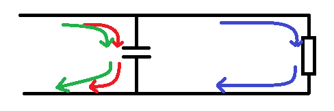
Bass Reflex:
I decided that I'd go with a bass reflex design, I've designed my enclosure using WinISD, my modelling decided two things for me.
First, as the driver I'm using cuts off rapidly below around 80Hz, I'll want to boost lower frequencies, To do this, I need a large enclosure, and need to use a tuned port, the tuned port allows the backwards pressure of the cone travel to create a positive pressure wave inside the box, that will then add to the pressure wave of the cone on it's forward excursion. (kind of like how an expansion pipe in an exhaust is designed to be a certain size so as to affect the pressure wave of expelled gasses from one cycle and create a vacuum to actually pull more gas out of the combustion chamber on a following cycle.)

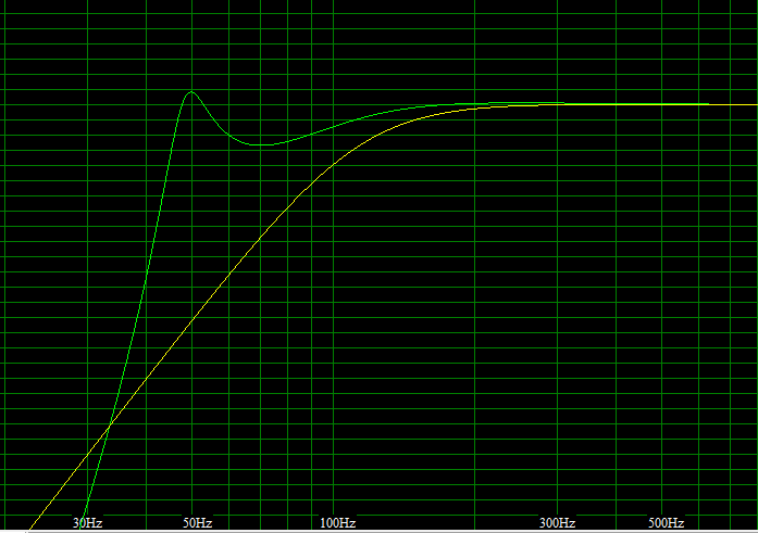
However, this does have an effect on the frequencies immediately around this frequency, as the port is tuned, it's this one frequency that is being boosted, this mechanical boost then falls away, however, this mechanical boost to the SPL is falling away at the same level that the drivers SPL is increasing with frequency. (i.e the addition of the two components means that the end frequency response is actually flat).

The volume of my box is 43Litres, this gives an overall height of 76cm and a width of 22cm, the depth is calculated at 25cm.
my ports are 2x 6.8cm circular ports each 16cm deep.

Next we have the problem that if I'm using the same model driver for the bass as I'm using for the midrange, putting that into the same enclosure is going to affect that driver also. The way around this problem is to put the midrange driver and tweeter into a separate speaker cabinet.
But, I don't want a floor standing speaker for a sub, and a bookshelf speaker, so instead I decided make one big cabinet, and have an internal shelf creating the top of one speaker and the bottom of the other. This is called creating a isolated cabinet.

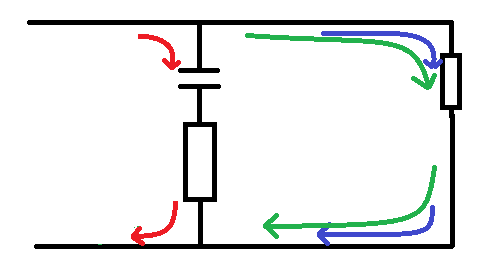
So I model a second enclosure, This time much smaller, I played with some parameters for creating a ported box, but in the end decided that a sealed box would be the way forward.
The reason that I created a sealed box is because in the frequency range that I'm interested in the frequency response of this drive is a fairly static line, I don't want to move it too much above or below that line, mechanically I want to keep it the same so there is no need for a fancy box.

The only design constraints of the second box is that:
>It has to be big enough not to restrict the mid range driver (too small of a sealed box would mean that a huge pressure was built up on the inward movement of the cone, and a vacuum would be created on the outward movement, this would provide resistance to the cone movement limiting the travel and altering the SPL.
>The tweeter must be ~20 cm above the shelf that seals the box to put this at ear height.

I ended up designing a box that was around 15 litres in size, and that was sealed.
the box is (just like the bottom box,) 22cm wide and 25cm deep, the height is 28cm

I can now see that:
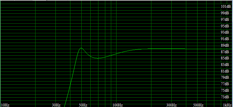
>My reflex cab now adequately centres around 88dB for all frequencies over 50Hz, (until the driver drops off).
>My top cabinet adequately centres around 88dB for frequencies over 200Hz, (until the driver cuts off).
>My tweeter has a response that's a little choppier than I would have liked, but reasonable enough for the job.

Driver placement:
So now I started looking at driver placement, I had decided when I was going to use the 4" driver that I wanted the drivers evenly spaced in a triangle, well, I decided that I still want the drivers evenly spaced, and that everything had to be proportionally spaced.

And here's how I designed that.

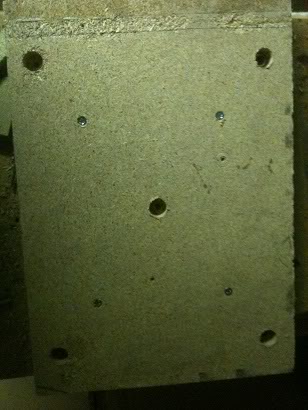
I know that my cabinet width will be 22cm, and that the drivers metal frame (outer diameter) is 13.8cm.

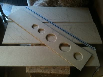
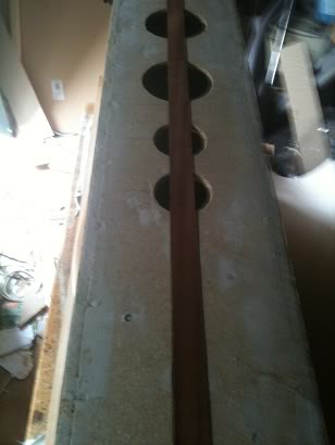
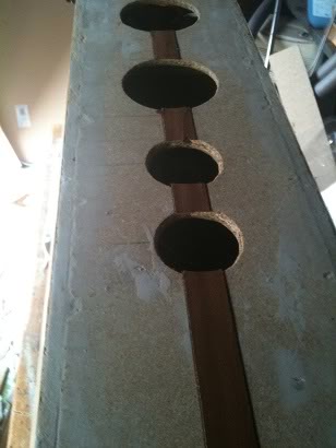
So, 22 - 13.8 = 8.2, I then divide that by two to give me a figure of 4.1cm, therefore I know that the spacing either side of my drivers will be 4.1cm, and I decided that I want to space the drivers, this far from the top, of the enclosure, and this much distance between each driver, I'll then half this gap when I get to the ports which as half the diameter of the speakers. (so the distance between these will be ~2cm.

I know that I'll put a lot of internal bracing on the inside of the cabinets to stop the cabinet flexing, (energy spent bending wood is not energy spent creating sound), I'll also be using some loosely packed wadding inside the enclosure to stop any standing waves developing which would cause internal echoes muddying the sound. so I increased my cabinet depth from 25cm to 30cm, (for both the top and bottom cabinets), this allows extra volume to be taken up with bracing, and allows for the material thickness of the board that I'll build the speakers in.

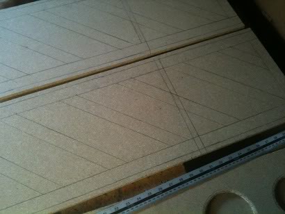
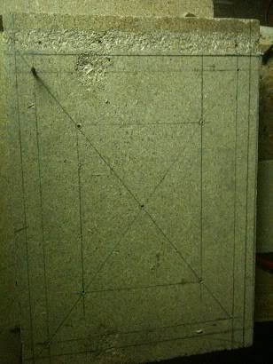
So now I have the box size, driver placements and port lengths, I've ready to draw up a 1/2 scale design that I can pin up in the garage so that I'll have a design to follow I'm also ready to start buying wood to build these from.

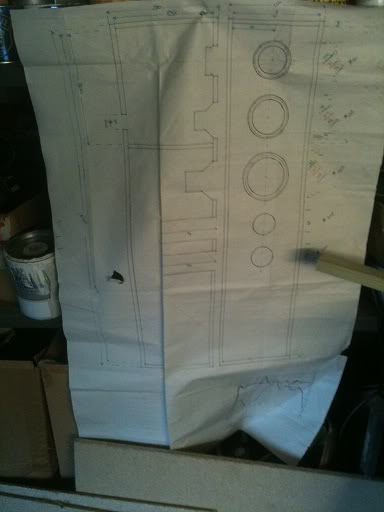
You may notice that I've drawn a logarithmic grid at the bottom of the design and plotted the end SPL/Freq chart to include driver parameters and cabinet effects. I'll use the values on this chart later.

Material:
The material that I'm choosing is based solely on price.
Many people argue that the best wood to build speakers from is plywood, as it is a very stiff wood that resists flexing, with the next choice being a medium density fibreboard. I however chose to use chipboard, it's the cheapest of the engineered woods, to put it bluntly, my costs could have doubled using MDF, and tripled using plywood. especially as I had to buy lengths that would fit inside my car to get them home from the store.

For bracing I chose a simple softwood baton 19 x 32mm
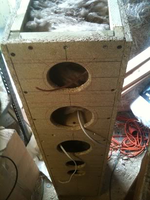
Construction:
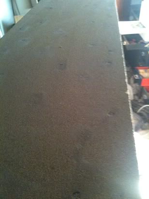
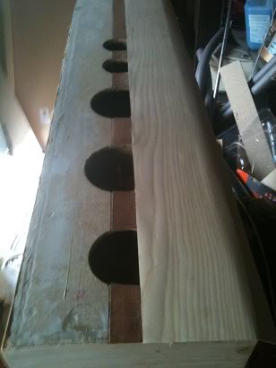
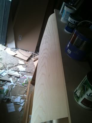
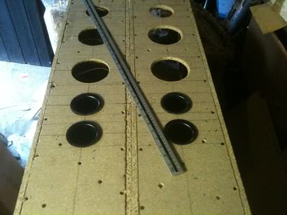
I started by cutting out all the pieces of board that I'd need to use, (14 in total)
the front baffle, 2 sides, the back, the top, bottom and the shelf. (obviously 2 sets to build two speakers!)

I then marked out and cut the front baffle so that I had an idea of what it'd look like, (at this point if it seemed too big I could go back and re-design. thankfully everything seemed ok.)

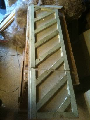
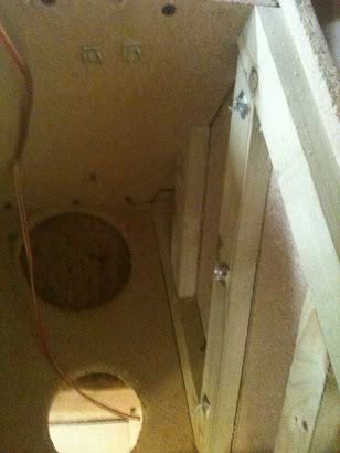
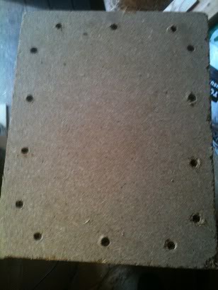
Next I marked the sides for the frames that would form a bases for the front, back, top and bottom to screw to, then I marked my braces.

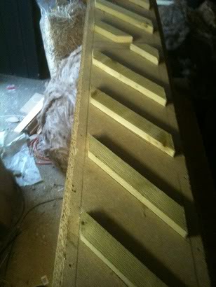
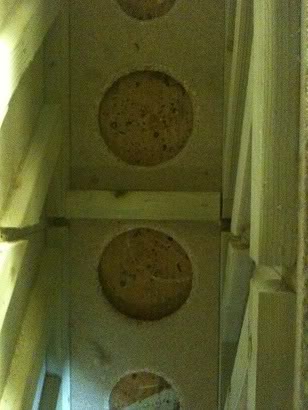
My braces sit at 45 degree angels, and are spaced 15cm apart, there is a break in the bracing where the shelf will sit.

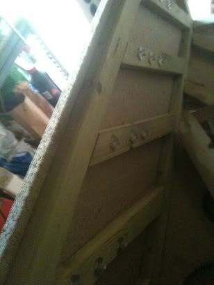
I then cut the batons to length using a mitre saw and glued and screwed these to the side.
the previously flexible side board was now very stiff, I repeated this for both sides.

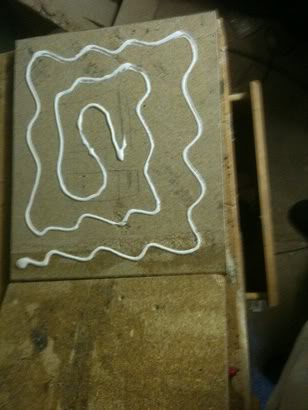
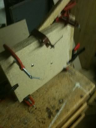
Next I marked a space for the braces on the front baffle (to sit in such a place that they would not interfere with the drivers nor reflex ports.) and glued and screwed these into place.

Finally I put the bracing onto the back also.


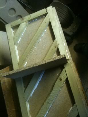
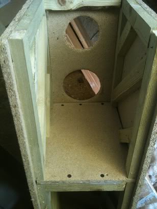
Once all the boards were adequately braced I attached the front baffle to the two sides,
I loosely fitted the back in place during the time that the glue was drying such that it'd help hold the box square.


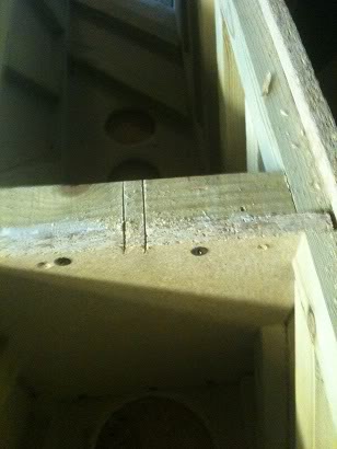
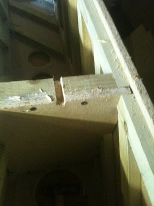
After the glue was dry I removed the back, and fitted the shelf in place, screwing a final baton to the shelf that the back would screw to, (as once the back was on I wouldn't be able to get inside to screw the shelf to a baton that was on the back!)


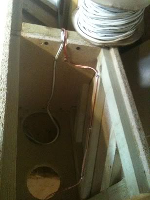
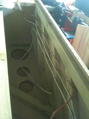
The next task was to cut a small slot in the shelf such that the speaker wires that would connect the midrange driver and tweeter to the connections on the back would have somewhere to sit.


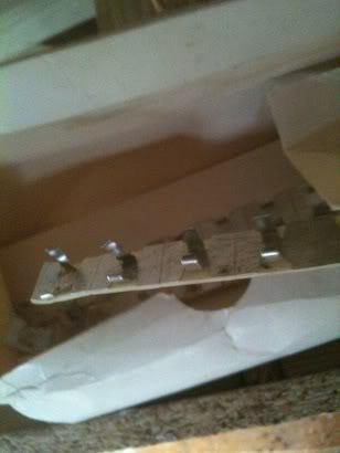
Finally I started wiring up the cabinet, I used small sticky backed cable clips to hold the wires to the side of the box, leaving enough cable poking out of the front of the box to attach drivers to, and leaving enough at the bottom of the box to attach to the crossover network later.
I've used two different colours of wire for the different drivers to help me identify what connection goes where later, the midrange and the bass driver use the same wire, so I've coloured bands onto the bass speaker wire to identify this.


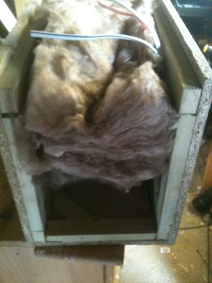
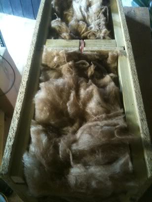
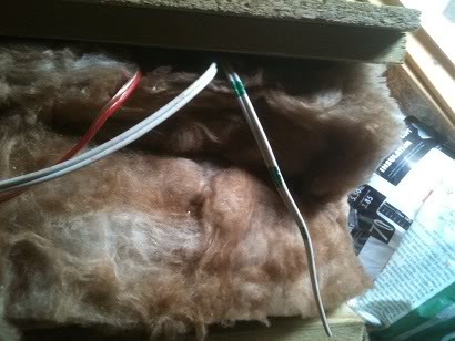
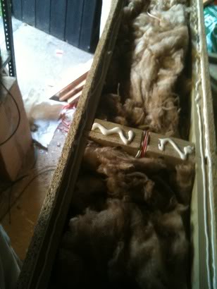
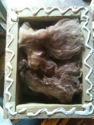
After the wires were in, I inserted my Wadding (a very loose) amount of sheep's wool/fibreglass mix,
This was cut to the width of the box, and then stretched to make it less dense and fill the box.
This wadding stops standing waves from developing inside the box, it would be possible to use egg box foam, basically you're trying to make the inside of the box as anechoic as possible.


Finally the back was glued and screwed into place.

After the glue on this was dry, the top and bottom of the box were added. (after making sure that the box was square of course!)


Wiring:
The drivers I'd chosen are 6Ohm speakers with an RMS power handling capability of 40Watts.
I don't want to have to take these speakers apart (ever) to replace the wiring, whilst the wiring would pull out of the clips easily, trying to work around the wadding and clips to install new wire at a later date would be a royal pain in the arse.

So I know that the RMS power I'll be applying to these speakers is ~40W
This means that the peak power is ~57Watts, (peak power is 1.414 * RMS), to be a bit conservative I'll increase this value again, I'll say that I want the power handling capabilities of my speaker wires to be ~80W

The drivers that I am using have an impedance of 6ohms.
knowing that Power = Voltage * Current, and voltage = Current * resistance.

I can say that with an power / resistance = current squared.

So at 80w, there is around 3.7amps of current going through the wires.

looking at this reference chart I can see that for 3.7Amps, (looking at the power transmission column) I need at least AWG gauge 16, (which is between SWG gauges 17 and 18 [so you'd use the biggest which is 17!] or 1.29mm diameter). (Yes, I'm look at lengths for transmission, I wouldn't say that lengths of over a meter are chassis wiring.)

Speaker stands:
When I started this project I had the thought in my mind that I'd just get some spikes for these speakers, and that would be that.
However, as I progressed through this project it became clear that spikes would be a bad idea, the speakers are heavy! spikes would just make huge holes in the floor/carpet so I had to come up with a different solution.

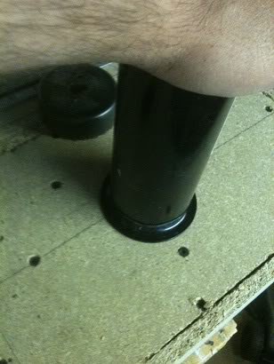
I decided that I'd make a kind of plinth for the speakers to sit on, to do this I cut a sheet of 3/4" chip board into two squares of equal size, that size was ~1" wider than the speakers and ~2" deeper. these two squares were glued together to make a 1.5" thick slab for the speakers to stand on.


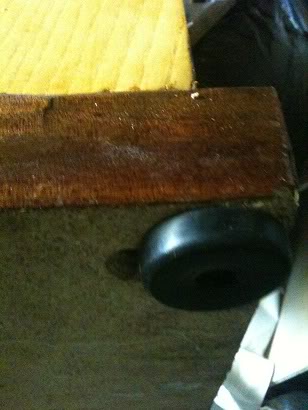
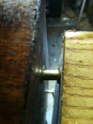
I decided that I wanted my speakers to float above this plinth, and decided that rather that sitting the speaker on spikes above this plinth, I made stand-offs using two brass screw cups and a short length of brass rod as a spacer. This spacer is placed around 1/2" into the bottom of the speaker (from the edge).


At this point I have not attached the plinth to the cabinet.

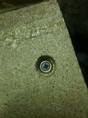
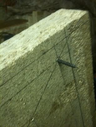
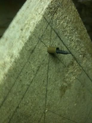
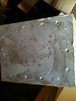
Now all the screw heads (sitting slightly under the surface as they were countersunk) were filled with wood filler, and sanded, In theory if, with care I could have painted the speakers now with a coat of primer and a nice black gloss finish and they'd have matched the TV.

But I have a very different plan for these speakers.

Veneer:
I have to admit that paint would have been a much much cheaper option than using real wood to finish these, however, real wood looks a lot nicer than paint.
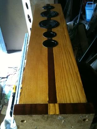
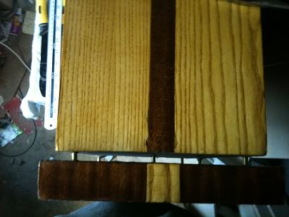
I've chosen to use an ash veneer (white ash), I've also decided that I'll put a strip of mahogany down the centre, and I'll reverse that motif on the stand.

I started at the side, then did the back, then the other side, finally leaving the front to do,

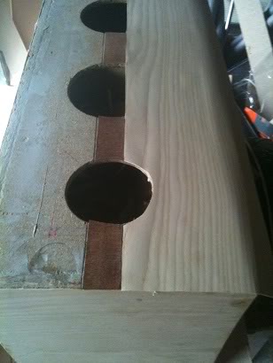
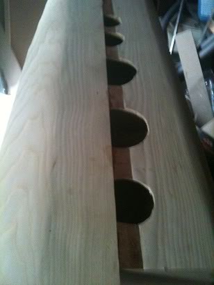
I started the front by first applying a 1 1/4" strip of mahogany wood to form a strip down the side, then I attached the ash veneer on either side of this, this means that the edges of the front, overlapped the front ensuring that the joint wouldn't be visible, then I completed the top. the base of the speaker is not covered because it will be on the floor and never seen.

As any part was attached that would have a hole in it was attached, the hole was cut out, this is because it made it much easier to see where the hole was when I could see half the hole than if I just had a completely covered box and had to measure where the holes were again.


I experimented with two ways to attach the veneer, either using a contact adhesive, where you spread the wet adhesive on both the box and the veneer, wait for the glue to dry to the point that it becomes tacky, then mate the two pieces together, However I found that the contact adhesive that I was using (which I normally use to attach carpet to PA speakers, didn't really give me enough time to adjust any pieces before the glue set and I couldn't adjust anything.


In the end I settled for using a PVA glue, and just being able to only attach one side per day leaving the glue overnight to dry, whilst applying plenty of weight on top of the side to hold the veneer flat.


After the glue dried I sanded the box to ensure that it was smooth, and that the edges of the veneer on the corners had a slight chamfer, any cracks in the finish were filled with a white wood filler and also sanded smooth, then I applied a French polish finish. The French polish that I used was a blonde polish, the reason I used white filler is because the polish applied an even stain to both the filler and the wood.
(I've covered how to apply a French polish in an earlier craft tutorial).

Finally the plinth was attached to the base of the enclosure, with the brass stand-offs, and rubber feet were attached to the plinth. The idea is that, hopefully, this will isolate the cabinet from the floor, which ideally should provide a better sounding speaker. (energy is absorbed in the rubber feet rather than being transmitted into the floor, the floor is going to vibrate, and the vibrating floor would create it's own sound. It'd rather defeat the point of all the careful design to get a flat response if you let the floor be an unregulated speaker as well.


Ports:
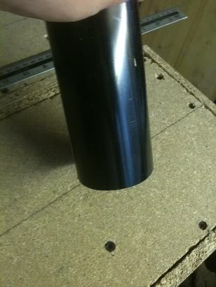
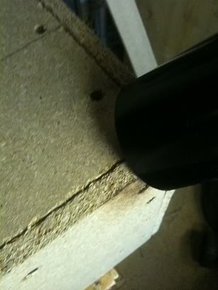
My reflex ports were 16cm in length, and 6.8cm, I chose 6.8cm as this is a standard sized downpipe for guttering, whilst you can buy pre-made speaker ports from speaker shops and manufacturers I decided that I'd make my own, the reason for this is a pure cost decision.

To make the reflex port I cut the downpipe to 17cm lengths I used a mitre saw to ensure that the cut was a true 90 degree cut.
After cutting the tube I heated the end of the tube gradually with a heat gun, using the corner of the speaker (before veneering it) as a mandrill to expand the pipe. when the edges were slightly flared I changed to using one of my hole saws as a mandrill, I did this as the corners were less sharp, (and less likely to tear the PVC pipe, also, since the hole saw is made of metal, it heats up as the air from the heat gun hits it, this means that as I'm turning the pipe the pipe doesn't cool down as much.

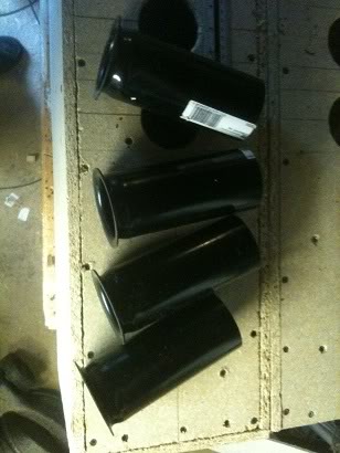
When the pipe was both flared and malleable enough, i pressed the pipe down onto a flat surface, creating a flat flared port at the front.

I've got 4 ports, so I went through this process 4 times.

The flare allows adhesive to be spread around the side of the pipe and underside of the flare, meaning that there is a much larger contact surface to hold the port to the speaker enclosure than if I'd just used straight pipe without the flare.


Crossovers:
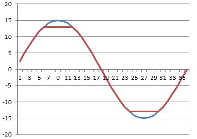
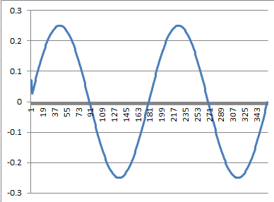
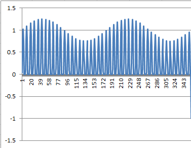
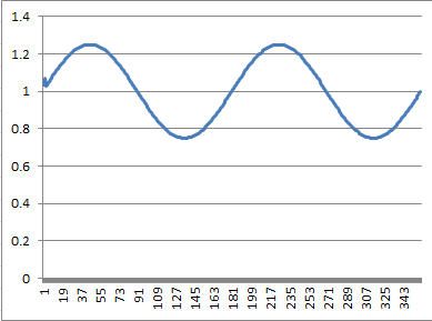
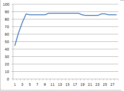
Knowing the frequency response of both my speakers, and the cabinet I now plotted the values in Excel, The program didn't give me a logarithmic graph, (it might be able to and I just might not know how).
I had three columns for my bass mid and treble, and was able to take values from my speaker data sheet, combine these with the values for my enclosure gain and attenuation, to find the final values of how these speakers would sound in the final enclosure.

From here, all I needed to do was select cross over points, and the fall off rate for the waveform.

I loosely decided that I'd like the bass response to be 0 - 200Hz, mid to cover 200 - 2000Hz and the tweeter to take over with everything after that as the values for the cross over points, and that a 6dB decay would be enough. (so I would be using a simple butter worth filter.)

This would make the calculated frequency response appear as this:

I investigated some components prices to either buy components for the crossover, or the wire of enamelled wire for winding my own inductors, but in the end found a pair of crossovers that I'd once bought for a different project and never used.

The only problem was that I didn't know what the values for the inductors were, and so didn't know the cross over points.

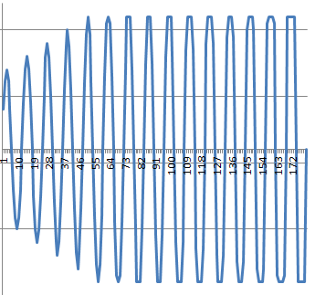
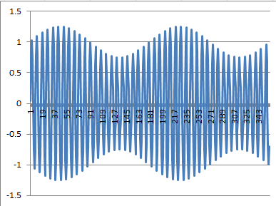
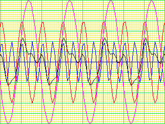
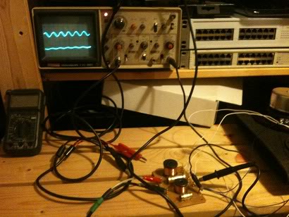
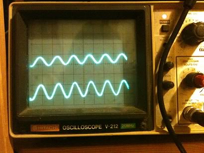
In order to get around this problem I used my signal generator and oscilloscope, setting frequencies of
10Hz, 20Hz, 30Hz, 40Hz, 50Hz, 60Hz, 70Hz, 80Hz, 90Hz, 100Hz 200Hz, 300Hz, 400Hz, 500Hz, 600Hz, 700Hz 800Hz, 900Hz 1KHz, 2KHz, 3KHz, 4KHz, 5KHz, 6KHz, 7KHz, 8KHz, 9KHz, 10KHz, and 20KHz in turn and measuring the output at the output for each driver.


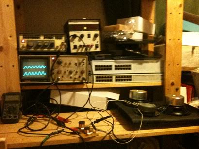
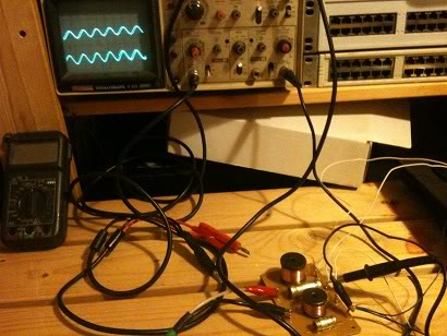
From this I was able to find that the crossover points on the cross over that I had was ~200Hz, and 6000Hz, Which, were a little way off from my Original selected values, however, when I changed my spreadsheet to use these values I found that the response would still be fairly flat. and I would not have to devise any attenuation network.
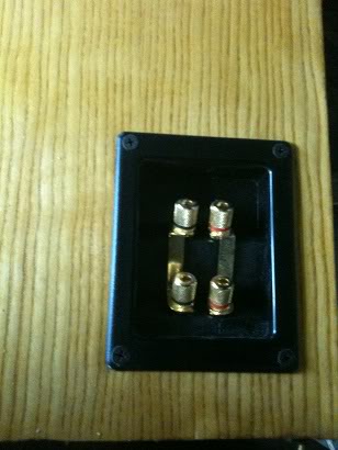
Bi-Wire:
I had decided early on that as I was only using 40W drivers that there was at least a slim chance that sometime in the future I'd probably want a second amplifier, if not to add more sound, then to add more headroom and allow me to turn down the amplifier.

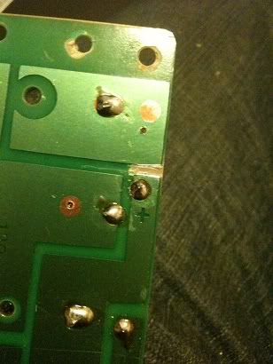
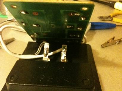
The crossover that I had was a single wire design, to make the cross over bi-wire able I had to cut a trace on the PCB, then drill a new hole and cut back some of the lacquer to be able to add a second input just on the bass side of the PCB.

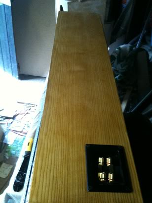
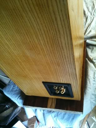
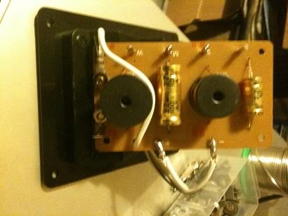
I also drilled two new holes in the PCB next to the heaviest inductor so that I could mount the crossover directly to the speaker binding posts. Rather than having to screw these to the bottom of the case (through a tiny hole that I could only fit one hand into and couldn't see through).

After the cross over was mounted, I attached the wires for the speakers to the posts on the crossover, and screwed it to the back of the cabinet.

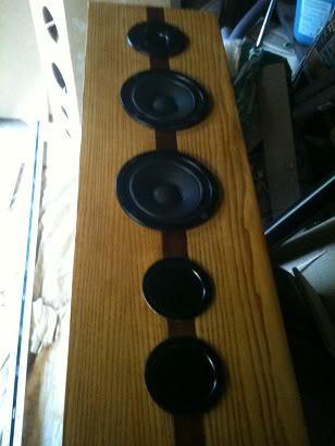
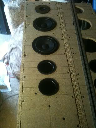
Then the speaker cones and tweeter were attached to the wire and screwed into the cabinet.


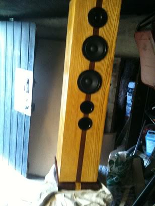
And the finished cabinet is here.

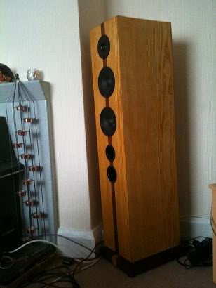
The more keen eyed may have seen that the mid and bass drivers were not centred in previous pictures when they were just loosely attached, in this final picture they are centred so that there is the same distance between each driver, and the same distance to each edge.

Costs:
The total cost was higher than I'd first intended. my goal was to try to build the speakers for less than £100, I did fail in this goal, even though I had lots of the materials already waiting to be used up from previous projects.

The wood, was bought in a large sheet 4 feet * 6feet, with a second 2foot x 6 foot sheet needed

the price for this was:
£9.99 for the small sheet.
£10.99 for the big sheet (yes, twice as big, but only a pound more).
(I had most of the wood already bought)

A pack of wooden baton.
£5.40 for 8 x 19x32mm in 1.8m lengths
(I had this laying around)

The wool wadding was left over loft insulation that I'd bought for something else, though this was £5 for the whole roll.

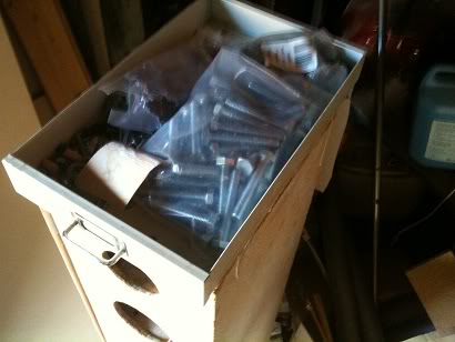
The screws cost £10 for a box (I already had these.)

The screw cups used in the stand-offs were £2 for a box of five hundred

The wood filler costs £3 for a tub. (I already had this.)

Glue costs ~£5 (I buy this in buckets and decant it into smaller bottles to use as it's cheaper that way. -so I already had this)

A sheet of 2/3" chip board used to make the plinths would also cost £9.99 (but I already had this -in fact this was made from the sides of a huge PA speaker that I once made and had to pull appart as I had nowhere to store them).

The length of brass rod used for the stand-offs is £5 per meter, I used about 12cm of this, but clearly you have to buy the whole meter! (and once again I already had this)

The veneer cost £50 including deliver for the Ash veneer, the Mahogany I had left over from an earlier project but would cost £10 for a sheet

The drain pipe used for the ports is around £5 for a 2m length, again even though you don't use it all you have to pay for it! (I already had this from previous speaker builds where I've made ports!)

The rubber feet are £2.99 for a pack of 4, (you need two packs).

The binding posts used on the back are ~5 each

I seem to remember that the crossovers cost me ~£5 for the pair a long time ago, But a quick look around suggests that £10 is not unreasonable for crossovers that don't have epic power handling capabilities

The speaker drivers 5.25" cost £7.99 each (and there are 4)
the dome tweeter cost £5.99 (and there are 2)

Speaker cable costs £1.25 a meter and there is around 4meters of wire in each cabinet (8 meters total)
I have not used Oxygen free copper because I can't hear the difference. If you can, then bully for you.
I again had cable left over from previous projects. (in fact I have a whole drum of cable (100meters of it)

The French polish is about £7 for a can, but guess what, I already had a can.

So... the cost for buying everything from scratch (if you want to replicate this) is:
£217.29
if you can't get a full 4x6 sheet of wood in or on your car you'll need 4 smaller sheets (and generate a lot of offcuts for other projects) and the cost will rise to ~£240)

As indicated above, I had lots of the stuff already, so the cost to me was around the £120 mark.

Basically, all I really bought for this project that I didn't already have was.
1 sheet of wood, (£9.99)
The screw cups (of which I used 10) (£2)
The rubber feet (£2.99 x2)
The binding posts (£5 x2)
The speakers (£7.99 x4)
The tweeters (5.99 x2)
and the ash veneer (£50)

So I've managed to clear up a lot of stuff out the garage, and create what I think are a fairly good looking speakers.

If I'd have painted rather than veneered the speakers then I'd have saved £50 on the wood and come in well under budget, but I don't think that would have resulted in as good of a finish on these speakers.

Final Analysis
~£200 sounds like a lot to spend on speakers, but you need to be realistic about what you're getting, these are more akin to a set of professional studio speakers than they are to a cheap set of 5.1 surround sound speakers.

If you want to buy a £60 set of speakers to have 5.1 surround then feel free, (they won't sound as good) on the other hand, if you dream of owning speakers in the £1,000 - £6,000 price range but can't quite afford that, then these speakers have the same physical look, and size, as well as the same kind of frequency responses, they do however lack the power handling of a set of more expensive speakers -but I don't find that a let down, as to my ears they are loud enough anyway.

The sound response is also fairly flat, when actually measured it is remarkably similar to the predicted values that I'd charted in Excel,
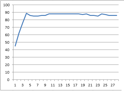
In the end I measured the response ~3m in front of the speakers as this was far enough away that I didn't feel that the dB meter would pick up more sound from being physically closer to any one speaker. At that distance the frequency response was as predicted poor at 10, 20, and 30 Hz, but started to roll on at 40Hz, at 50Hz, I reached 65dB, this then stayed the same altering by not more than 1dB above or below this level right up to 14KHz, where I stopped measuring as my hearing drops off at this frequency! -so I don't care if it's flat after this!!

The amplifier I used for this test was a Samson Servo 150, which is a studio/reference type amplifier, outputting 75W per channel (RMS) into 4Ohms, I didn't turn the amplifier up full, just to a comfortable level.

They sound really good when listening with a variety of music styles. -and that, rather than flat frequency audiophile BS is what matters. -Though they do come complete with the flat response audiophile BS too :)

Perhaps the thing that surprised me the most about these speakers was the actual bass response, the bass is by no means booming, indeed it's not meant to be, if it were I'd have designed a frequency response like a roller coaster. What I find surprising about the bass response is that it is there, and it's not quite, it's the same kind of level of sound as you're getting from other frequencies. I was surprised that this tiny 5.25" driver was actually capable of producing those frequencies.

When playing music through these I'm able to hear bass frequencies that previously I wasn't even aware existed on a track.

Throughout the build I had been thinking that at the end I may need to upgrade the bass speaker to a 6, 6.5, 7" possibly even 8" speaker to actually get a decent amount volume of bass frequencies, But as it turns out. I don't need to.