Showing posts with label Home improvement. Show all posts

Monday, May 27, 2013

Making an extension lead, (plug end)

I made a post last week about adding an extension lead socket to a length of wire.

Now I'm going to detail the plug end.


So start by looking at the pins, here you'll find two screw holes that secure the male plug pin part to the back cover that you hold whilst plugging or unplugging.

undo these screws and remove the back cover, then put the back cover onto the wire that you're using to make the extension lead, (or the flex for the equipment that you're attaching the plug to) so that you;ll be able to close the plug later once the wires are connectted.

Again, start by stripping your wire.
then cutting the phase wires slightly shorter than your earth wire, (so that if the cable is strained, your equipment would go dead before it became unearthed)


Now loosen the cable clamp and attach the wires to the plug terminals.

Finally clamp the cable in the cable clamp, push the back cover on, and screw it back into place with the screws that are next to the plugs inside the plug shroud.


Your extension lead is now complete.


Monday, May 20, 2013

Making an extension lead, (socket end)

So I dealt with mains electricity a couple of weeks ago.

Now this is a quick post on how to put together an extension lead.

At the end of the post on mains power I was pretty keen to stress that there were colour codes associated with mains power, well, as it happens the cable that I was able to buy for my 3phase extension lead does not conform to that colour scheme.

The cable has conductors that are Brown Blue and black with a green and yellow earth conductor.

So to start,
The cable I'm making will be a 16amp three phase 240 Volt cable.

 That means a 4 pin blue "commando" socket is needed. There are fairly uncommon in the UK (as our 3phase tends to have 415 volts. quite uncommon in the US (where the three phases are 120volts) but apparently is quite common in Sweeden. so you can get the plugs you want.

I found these plugs (and sockets) by searching Ebay for IP44, and IEC 60309.

You can find these at screw fix, (where they are £11 for each plug -I paid £1 each for five on eBay) sockets are also available at screw fix, but again I found them cheaper on line.
(screw fix is a nationwide UK distributor of all sorts of trade type building materials, it's open to the public, so if you can't wait for an item to ship they may be the best bet!

So I'm going to start with he socket end.

Take the socket apart such that the back cover is away from the connectors,slide the back cover over the wire (with the open side facing the bare end) so that you'll be ready to seal up your connector later!
To remove the back of the socket use the two cross head screws that are located inside the grip portions.

Now take your 4 core wire and removing some of the outer insulation.
Then cut the phase leads to be shorter than the earth lead -the reason for doing this is that if the cable were ever put under strain and connections were to come out of the plug then the equipment you;re using would stay earthed, the worst scenario for electricity would be using a piece of equipment that was unearthed, that malfunctioned and became live, then you're the path to earth! By leaving the earth lead with some slack in to you're able to know that safety can be maintained, even if the cable has been put under such strain that conductors have started being pulled from connecting plug pins!


Now open up the cable clamp on the blue half of the connector and attach the wires into the holes indicated, with the brown black and blue wires being the phase wires and the green and yellow being the earth wires.


Then close up the cable clamp.


Now slide the back of the lead into place.


you can see a large black rubber washer, (it's about a half inch thick).

This is what seals the unit from weather (that and the little black o-ring on the other end)

Once you've gotten the back in place and screwed down, slide the final part of the back into place.

 this screws down squashing the rubber washer forcing it to grip the cable and provide a waterproof seal.

Finally, you have a lead with a socket on the end.


Monday, May 06, 2013

Electronics lessons: Mains Power -single phase and three phase

Whilst writing this blog I've stayed away from things that I would consider dangerous.

That is to say I've completed some projects that I've felt were either too big to document, (like when I put up my new storage shed in the garden and put electrics and lights etc in.) -at the time my thoughts were like this. it's OK to tell someone to stick bits of wood together to make a speaker, it's OK to say to people use this step down transformer and deal with the safe voltage that comes out the other side. I even thought it fine to tell people to stick electrodes into water to generate hydrogen/oxygen gases!

But big scary voltages have been something that I've stayed away from, the thing about mains utilities is that, you can smell gas, and know to shut off the supply and get out. you can see water and hopefully have the intelligence to get out before drowning. Electricity is completely invisible, it's not a substance, it's a force.

Anyway, that might give you an insight as to how I feel about mains electricity. it's dangerous to the point of deadly, and too much confidence can lead to mistakes that ultimately can kill you.

As a point of reference I live in the UK, this means that for me, voltages come in 120v for site tools, (where the 120v is considered safer due to lower voltages) this voltage is obtained by using those little yellow transformer boxes.

240v comes into every homes, (at least every connected home, I suppose off grid homes might make their own standards).

440V is considered industrial and is what most three phase power outlets are going to be using.

Voltages are measures with respect to neutral, live - neutral.

Single phase

Single phase power is an alternating waveform going from the positive extreme of the voltage swing to the negative extreme of the voltage swing in one wave form.

Single phase is what I've mostly dealt with, it's easy to visualise, easy to look at and easy to understand. remember that the positive is measured with respect to neutral, not with respect to ground.

Sometimes a single phase supply is actually a 2 phase supply, where instead of a virtual earth, or earthed neutral, there are two hot phases where the phases are 180 degrees apart.
the sum of the phases is zero, (e.g at 0 degrees phase 1 is 0v, phase two is at 180 degrees and is also 0v, at 90degrees, phase 1 is +120v and phase two is 270 degrees and -120, (+120 + -120 = 0v), the total potential difference between the two phases is 240 volts, (120 - -120 = 240)


Three phase


Here's where it starts to get a little more complicated.
Now there are three phases, each phase is 120 degrees behind the next, they are still sine waves, and they are still measured with respect to neutral, but there is no neutral in the transmission line, -when power enters your premises in a single phase set-up there is a live and neutral line. when you get three phase there is only 3 live wires, no neutral. (you can make a neutral by connecting all the phases together, because the sum of the phases is zero) -but I'll cover that in a later lesson.

You can see at 90 degrees now phase 1 (blue) is at at the top of it's rising cycle 240v, and phase 2 (green) is just coming up from the bottom (so during it's rising cycle) and is -120v, whilst phase 3 (red) is getting towards the bottom of it's falling part of the cycle, and is -120V
240 + -120 + -120 = 0

Colour Codes

Colour codes for wires are important, in that they will let you know what wire does what. everyone knows that green/yellow stripe is earth, and it's safe to touch. but what if I wired a plug so that the earth wire was used as a live conductor.
it's just a bit of copper, fundamentally there is nothing to stop me from doing that, provided I wire the other end the same way, where's the problem?

The problem is what happens when I'm out, and whatever appliance I've wired badly breaks, what if my wife/girlfriend/boyfriend/husband/friend/son/daughter/mother/father/grandparent etc decides that they just want to check the fuse on the plug, then they see the wires connected wrongly, so think that might be the problem. or something see's an earth wire, and decides that they can splice that wire to earth something else, -except it's not earth, it's live, and they are probably now dead.

Colour codes are set by the IEE.

for single phase systems.
Brown = Live, (the old colour was red)
Blue = Neutral, (the old colour was black)
Green and yellow stripe = Earth, (the old colour might be plain green)

for three phase systems,
Brown = Phase 1 (old colour was red)
Black = Phase 2 (old colour was yellow)
Grey = Phase 3 (old colour was Blue)
Blue = Neutral (old colour was black)

This means that if you are adding new wiring to an old system, don't just connect the new blue wire (N) to the old blue wire (P3), or the new black wire, (P2) to the old black wire (N)

you may also find three phase systems where the conductor colours are Brown, brown brown for P1, P2 and P3, with a blue for earth.

Earth (as always) is green yellow stripe.

earth may also be the bare wire in fixed installations, (where solid core wire is used rather than stranded wire).


Monday, April 29, 2013

Filing, -photographing documents en-mass

Filing is something that I'm both good at, and bad at.

There comes a point in most peoples lives when they are quite literally bogged down with paper. from bank statements, credit card statements, phone bills, TV bills, water and gas bills, old insurance documents...

All pretty important stuff important at the time to keep in case of dispute, and important later on as an aid to memory, (like remembering how much something cost when you bought it!)
having a receipt past the warranty period seems silly. But given a few years ago my house was robbed and I lost several possessions, it now seems worthwhile keeping receipts for things, just in case the worst should happen and I end up in the position again of trying to remember, exactly what model of tool did I have...

Because -let's face it. with an expensive tool like a welder you don't want to say I had a 260Amp MIG welder (when in fact I had a 150 Amp welder), if the original items were ever recovered you'd have some explaining to do as to how you claimed for something that you just didn't have! on the other hand, you don't want to err on the side of caution and say I think it was the 90Amp model, because then you won't have the same tools that you started off with.

So, it seems logical to scan or photograph documents.

To that end on Sunday I had a filing day. a day where I take the large bag of bills, bank statements and receipts that I've let pile up over the past few months or year and commit them to a digital format. Rather than scan them as I have done in the past this time I decided that I'd photograph them as this would be faster.

So I rigged up a little ledge to put my phone on such that it was at a distance that a single letter would fill the photo taken.

This involved a length of wood which I balanced on top of a few items with my iPhone sat on top of it. to take a photo I could just press the screen, and then move documents into view, press, put another document in view (on top of the previous letter so I didn't even need to fiddle with the document to align the letter in the phone screen), then press the take photo button.

It ended up as a pretty slick process, I got a whole ream of documents, (yeah actually 500!) scanned in a few hours.

The only think left to do is sort them into folders:
(for example my bank statements are sorted into a folder called bank, and they are named by the date the statement was sent. yyyy-mm-dd that way when sorted into folders they appear in chronological order and can be viewed sequentially.)

Here's a picture of the make shift camera holding set-up that I used to speed up the photo taking process.

Monday, April 15, 2013

Making a Lego Table

So this is a nice short post that details the Lego table that was made for my Daughters birthday.


It's a pretty simple idea, rather than having lego all over the floor, (not that this will stop that happening) a special lego table is created, where models can be created and worked on, perhaps over a number of days.

The basis for this table is a cupboard from Ikea that is a bit like those old school cupboards, there are some plastic trays that will be used to store the lego in.

On the top of the table base boards are glued to the top.

This table uses 32 x 32 piece boards, (three of them) and 16 x 32 stud boards, (4 of them) and a single 16 x 16 stud board

The total areas therefore is 48 studs wide (32 + 16) and 112 studs long (32 + 32 + 32 + 16)
there is an equal border, (about a 3 stud lego brick size) around the whole top

The boards were glue using solvent free evo stick (contact adhesive) glue. obviously a solvent based glue would melt the ABS plastic that is used to make Lego!

When the table is all put together it looks like this:


You can just about see the way that the boards are offset to try to minimise the lines.


Monday, January 21, 2013

Making a coat stand for a child

So I thought it was about time I finally wrote up the build of a coat stand that I made, (about 2 years ago).

The idea for this coat stand was sent to me by my friend who said I should make one for my daughter. I forget the exact link to the inspiration, but I do remember it was on Ana Whites website called "Knock off Wood, free woodworking plans for furniture http://ana-white.com/"

If you have a few days you should definitely check out that site, it's chock full of amazing furniture, includes plans.

You don't have to follow the plans, you can be like me and decide to make your own plans up in your head to build approximate versions of stuff on the site.

Anyway, now that I've covered where the idea came from it seems only right to give a little background.

Design
At the time I made this coat stand my daughter was about 3, she was getting to an age when you should care about your stuff, and start hanging up your coat etc, but not yet at an age where she could reach regular height coat hooks.

So the solution was obviously to build her a coat stand more suited for her.

This means that it should have pegs reachable by a 3 year old who stands about 3 feet tall, (so the height of the stand is about 4 feet, so she'd have to reach up at the start, but would not immediatly outgrown the stand.

I decided that the coat stand would need four pegs that would be at her current arm height that she could hand coats on, and a further 4 hat stand type pegs, to put hats on of course. As she grew the hat stand pegs would eventually become coat pegs.

So the parameters for design are:
four coat pegs, at about 3 feet from the ground, four hat pegs about 1 foot above the coat pegs, a stable base is a must.


Materials,
I decided that I'd use softwood to make this coat stand, it's easy to work with, and has a variety of finishing options from plain no finish, or varnish, to any colour as it's easy to paint.

The pegs I decided would be made of dowel. (12mm dowel so that they would not easily snap)

To build with nice proportions of 12mm diameter dowel pegs I decided that 48mm square pine was the best wood to use.


Onto the build
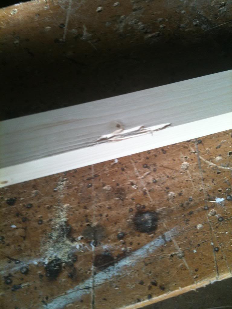
So the biggest gripe I had with the materials was the condition that it was in. I bought square planed timber from Wickes, this should be ready to go. if I'd bought rough sawn wood I'd agree that imperfections were ok.

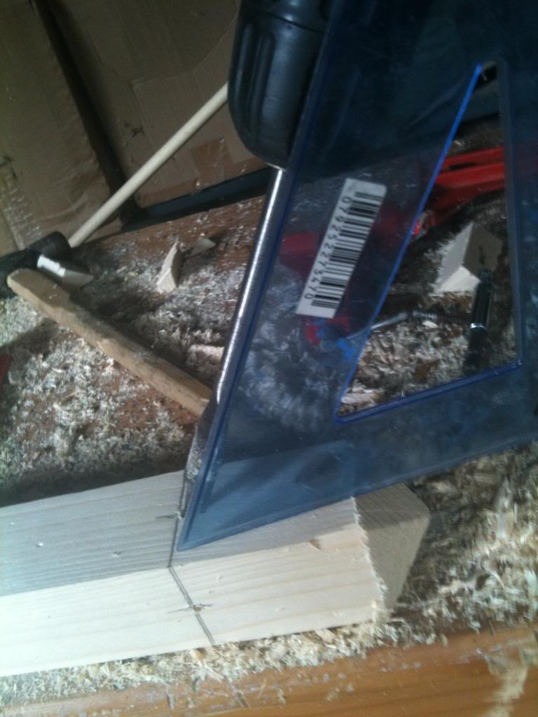
So the first job was to inspect your materials and work out what I could do to cut out imperfections. like this:

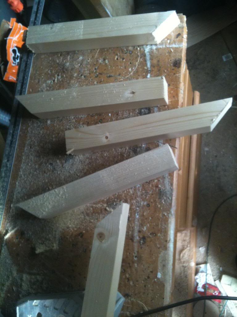
Once I'd decided the best cuts for the wood (and there is no exact science for this that I'm aware of) I started cutting, setting the blade of my saw to 45 degrees I made a cut around 14 inches down the length of the wood.
then set the blade back to 90 degrees to make the next cut again about 14 inches down the length of wood.
This will gave me two bits of wood, with one square cut end, and the other end cut at 45 degrees.

Repeating the above gave me four of these. these will be the legs of the coat stand.


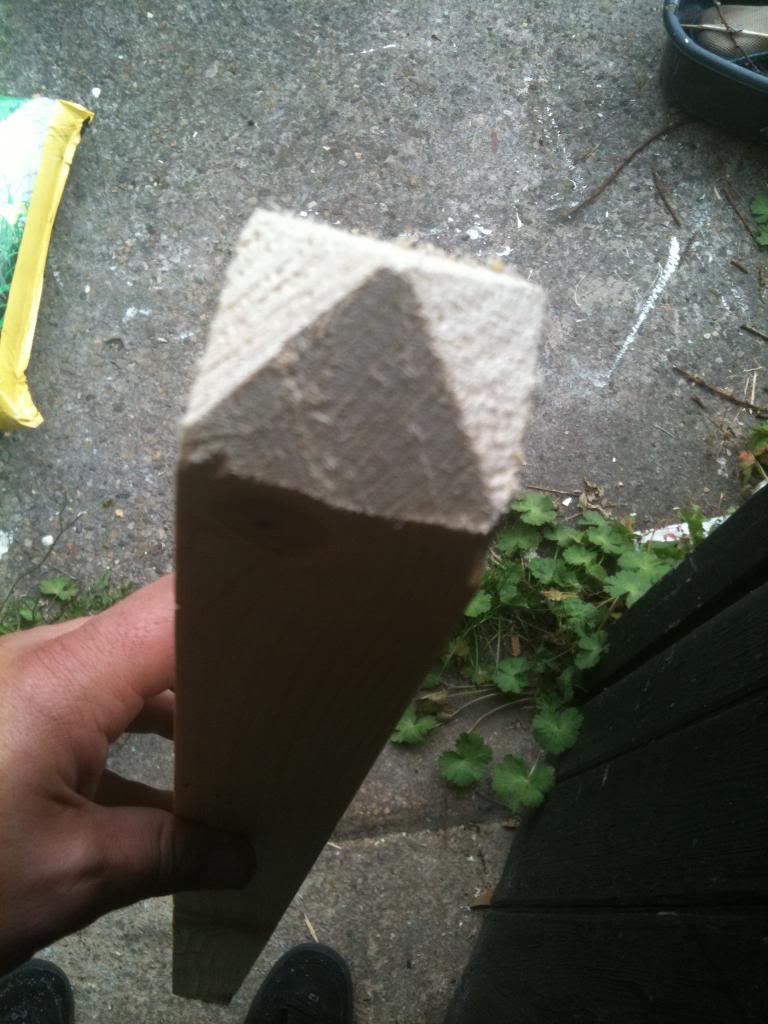
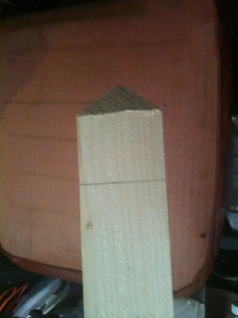
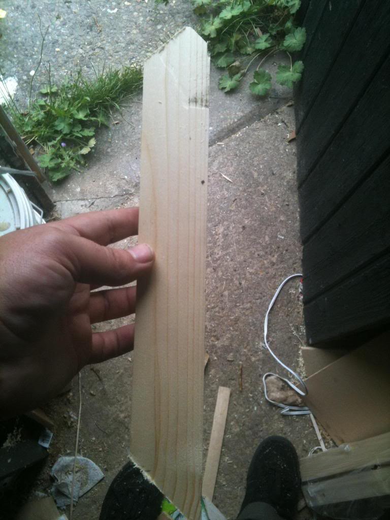
Next I made a 45 degree cut in the remaining (approximately 1 meter) length of wood.
Then flipped it over and made another 45 degree cut, then 2 more cuts and I had a square point.

I did this at the top and the bottom


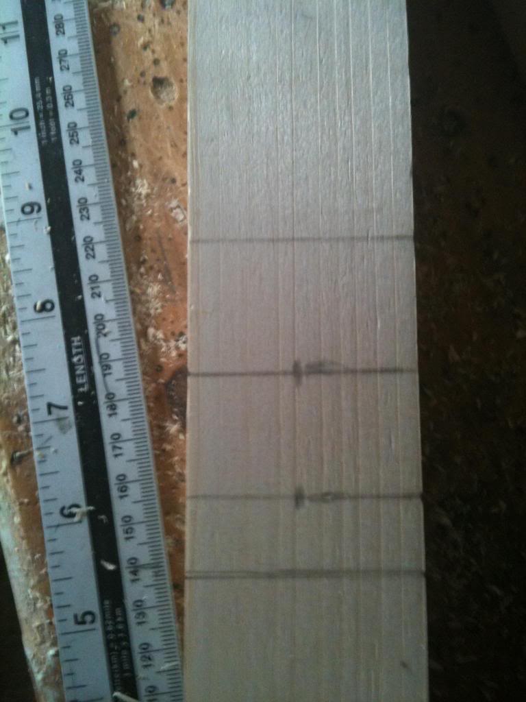
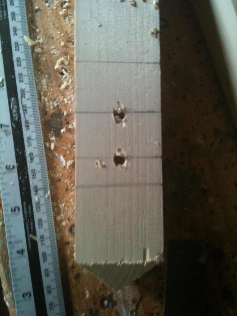
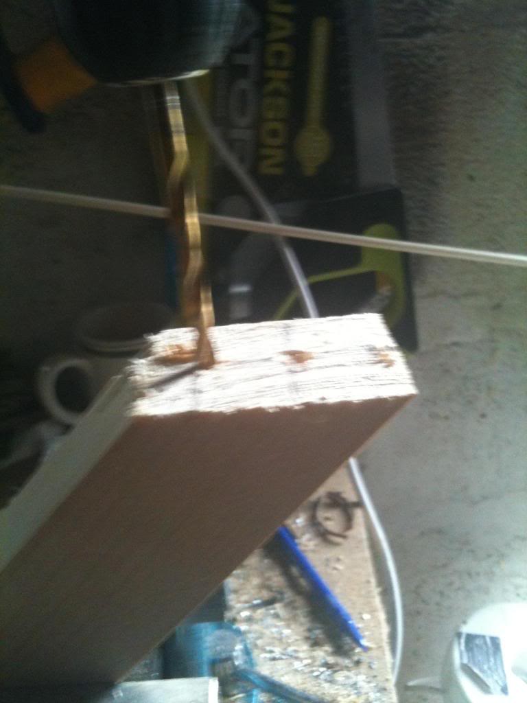
Next I marked a ring about 1.5 inches from the bottom of the base of the point, this is where the legs will attach.


And a further ring about a half inch above that, (and another about an inch after that)


The centre of these lines are drilled with a 6mm drill bit, (ready to recieve a dowel peg to make a strong joint)


 Back to the legs.

Clearly the 45 degree cut is what will butt against the centre poll that I've been busy marking and drilling and making pointy.

But the legs do need some further work, and the moment the base will be the corner of the block of wood.

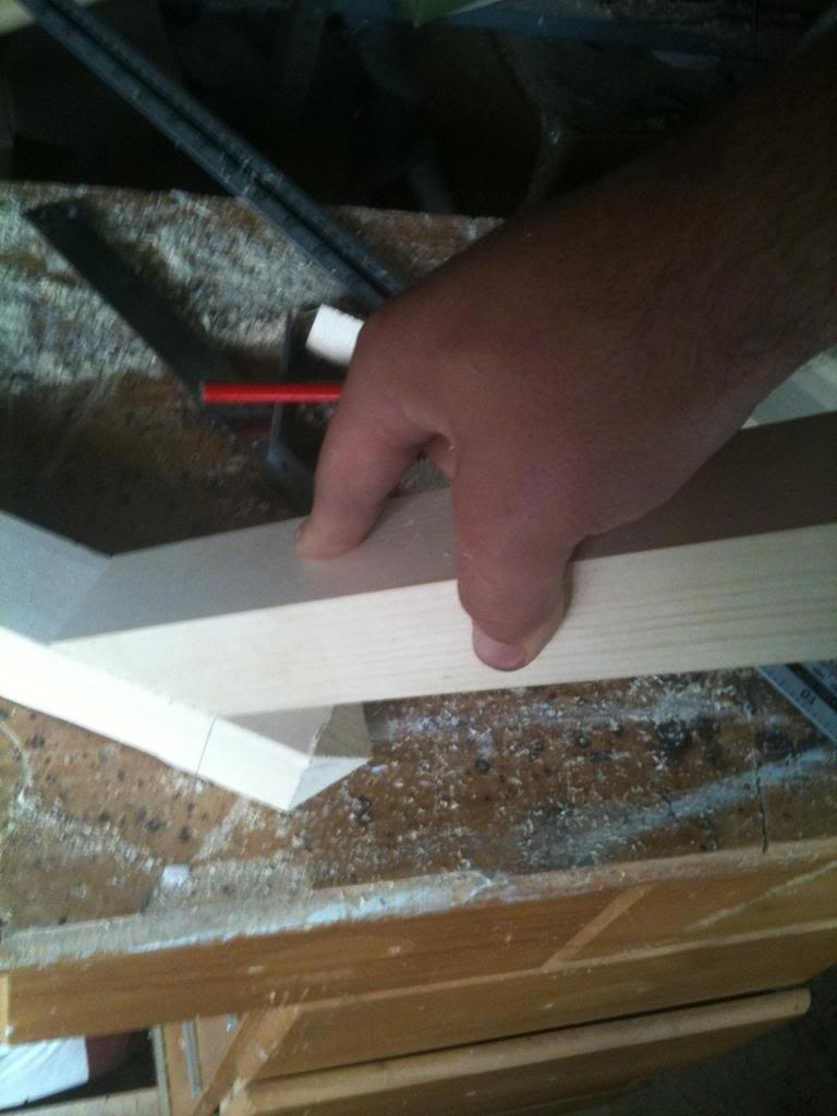
so I set my saw back to 45 degrees and cut an angle in the opposing direction to the mitre that will face the centre poll, then I cut again to smooth off the top of the leg.


I now marked and drilled the long mitred face of the leg, to recieve dowel pegs and glue.


Now I did a dry test of matching the joints (A dry test is where you put it all together without glue, this allows you to make any final adjustments before it's too late!!)


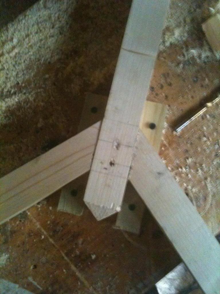
Finally I put dowel pegs and glue on the joint.
I set the first two joints against a table using wooden blocks screwed to the top to clamp it in position.
The final two legs were arranged with the blocks clamped to the centre stand, then the leg clamped to the blocks, (allowing the odd angled leg to be clamped to the stand)


Finally I drilled 12mm holes in the stand at about 4 feet from the floor. a hole going straight through, and another hole about an inch higher going through the other way.

Then I glued an 8 inch length of dowel into the holes, (with 3" sticking out of either side")

The hat pegs were drilled into the top of the stand, (about an inch and a half from the top, so the pegs are about as far along the centre poll as the legs are up it).

I don't have a drill press with a moveable table so I used a set square, and roughly lined the drill up to drill coat pegs at an angle into the top of the stand.


Lengths of 12mm dowel we then glued into these holes.

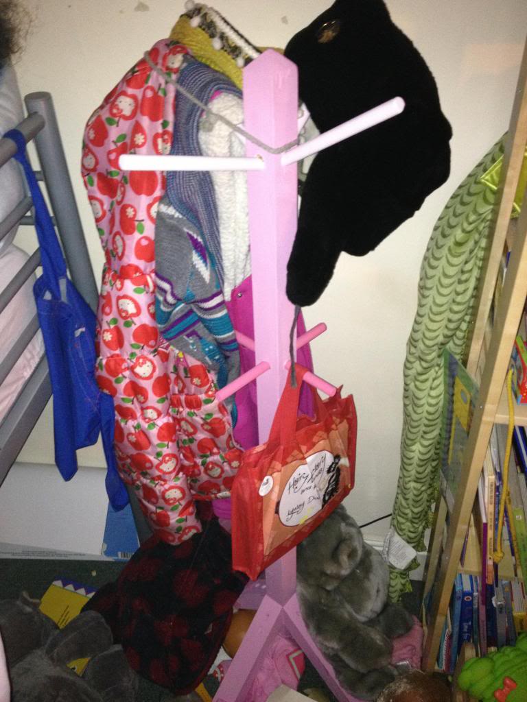
Finally the coat stand was painted a pastle pink colour.


Monday, July 30, 2012

Fitting a second Antenna feed

When an antenna gets fitted to the roof of your house, there is a good chance that there will be just one cable coming down the side of the house, into your living room, or TV room.

Of course this is a little bit useless if you have more than one TV.

So here is a quick and simple how to split an antenna.

The pictures here show an antenna that has been routed through the inside of a house under the eaves into attic space, the process for splitting an antenna feed outside if the same, however you may wish to include a water proof box over the splitting equipment.

In this installation the split at the antenna is being done at the same time the antenna is being installed, but fundamentally it makes no difference. (the only difference is the colour of the cables used in the end!)

First, in order to perform this splitting task you will need to first purchase an antenna splitting device,
this is a small transformed that is used for impedance matching.
If you just split the cable into a Y shape then it would work, but the signal from the antenna would be loaded, and thus pretty weak.

The Antenna feed has an impedance of 75Ohms, the circuit inside your TV has an impedance of 75Ohms, if you put another TV in parallel then you will halve the impedance to 37.5 Ohms.

So we use a transformer.
this transformer has one input coil with an impedance of 75 Ohms, and two output coils each with an impedance of 75 Ohms.

This will serve to effectively half the strength of the signal from the arial going to each set, so if you have a weak signal you should consider a splitter with an amplifier.

Start.
Cut the antenna wire at a point where it will be convenient to fasten the splitter box to a roof joist.
Once you have cut the antenna wire, peel back and cut off approximately 10mm of the outer insulation, and fold the screen wire of the coax cable down to cover the outer insulation sheath.

Now cut approximately 7mm of the inner insulation away from the solid signal conductor.
Screw on an F connector.
This will need to be attached to the "IN" connector on your signal splitter.

Now, you need to run cables through your roof space and down walls to the locations that you want your antenna outlets to be.
Once you have your cable in the correct place, use cable tacks to attach to joists, and C clips to secure the cable to masonry.

At the splitter end, attach more F connectors in a similar fashion to how you connected the antenna feeds F connector.

Now fix your splitter to a joist and attach the cables, the antenna feed going to the "IN" socket, and each feed to your TVs going to the "OUT" sockets.


At the other end of the cable you now want to attach an antenna plug to go into the back of your TV.

First, put the bottom screw cover for the antenna plug onto the wire.


Now remove approximately 15mm of the outer sheath.
Pull the screen wire of the coax down and over the insulation, then remove the inner conductor leaving around 2mm of the insulator to stop the screen wire accidentally touching the signal wire.


Now you need to attach the four pronged cable clip, this clip is intended to make good contact with the wire, squeeze the clips by hand to secure this to the connector and attach the tip part of the plug to the signal wire, place it over the end of the cable, (trim the signal conductor as appropriate) and secure by tightening the small screw onto the signal wire.


Now place the metal screen over the tip assembly.


The place the plastic plug cover over the screen and secure using the bottom screw cover that you put onto the antenna wire at the start.


Plug in a TV and ensure that you can receive a connection.

If you can't receive a connection is seems likely that either there is a break in the cable, or your screen wire is touching the signal wire at one of the connectors.

Monday, October 24, 2011

Changing Venetian Blinds

There are many reasons why you may want to change the slatted blinds in your house, perhaps you are re-decorating, changing the scenery, perhaps the old ones have been there a long time, or perhaps, like me, you have cats which are little bastards that chew everything they get near to.

Having chewed a couple of blind slats, the blinds now have to be changed, since I was doing this anyway it seemed only fitting that I should write and post up a small how to do this, there will be plenty of pictures.

Firstly, this is the damaged blind slats.

To remove the old blinds look at where the blinds are hung on the wall, these binds, (originally from B&Q) have a small sliding door that you open to be able to remove the top of the blind from it's bracket.

Once the door is opened the blind can be removed from this end, and will come out the other end without the need to remove the door on that side.

When you are buying the replacement blind you are pretty unlikely to find a blind that will fit your window perfectly, (you'd think in a fairly modern house where every house looks like the last, the people who make cookie cutter houses might have talked to the people who make binds and maybe decided on what a good window size was, but apparently that would have been too hard.

So start by measuring the width of the window (left to right) in this case the window measured 115cm you then need to measure the height of the window from top to bottom, this is called the drop and for the blind I'm changing the drop needs to be 103cm
Then you need to go to the shop and buy the closest fitting blind, in my case this was a 110cm wide blind with a drop of 180cm.

Once you've purchased your blinds, you'll then need to go about making them fit.
Making them fit width wise is pretty easy, (but very time consuming.)

I need to shorted my blind by 7cm, this means removing 3.5cm from each side.
Start by using a small hack saw to cut 3.5cm from each end at the top bracket part that holds the strings, then using scissors, but 3.5cm from each end of each and every slat -I did warm you it was time consuming!!

Once you're done altering the top bracket and the slats, you now need to shorten the bar at the bottom.

To do this you need to remove the plastic end caps -which should pull off, then as before cut 3.5cm from each end with a saw.

now that the blind will fit into the window recess, put the blind into the bracket, and the top and let the blinds go down, the drop of the blinds is still far too great for the window.

chose a slat that's a couple of slats lower than the slat that you think should go at the bottom, (the aim is to have a couple of slats sitting on the bottom bar so that the blind doesn't distort when you change the slat angles.) mark this slat, a big black marker pen will do the trick, or cutting it up with the scissors.

Now take the blind out of the windows and rest it on a large flat surface.
The bottom bar has a series of white plugs in it, these need to be prized out so that you can get the the pull strings for the blind.

once the clips are out, you should be able to remove the strings the hold up the blinds, which are held into the bar with a small knot. when you undo the knot the pull strings for the blind should come out of the bar.
the bar will now be held in the threaded ladder part of the setup that controls the blinds angle.

you can just slid the bar sideways out of this laddered thread.


Pull the main threads out of the slats, up to the slat that you marked, (clearly do take out the slat that you drew all over!) then pull the slats sideways out of the laddered thread.


now slide the bar into the place on the laddered thread where your marked slat was, and thread the pull strings back into the bar.
(if you cut the nylon pull strings, then make be frayed now. use a lighter to heat the frayed end of the nylon cord, then whilst it is still warm quickly twist it between your fingers.


Once you've threaded the draw cord through, you'll need to tie a small knot in the string so that the bar will sit on this and raise/lower with the string.

Then cut off the spare string. and remove all but about three of the laddered thread.

Now you can poke the end of the string into the hole in the bottom of the blind, twist up and poke in the dangling thin ladder threads into this hole also. then pop the small cap back on to hold the threads inside the bar.


Finally hang the blind into the brackets that were already on the wall, and adjust the draw strings as necessary.
(to adjust the draw strings pull the knot from the toggle and tie a new know further up the draw string for the toggle to rest on, and cut away the draw string that is spare.)

Finally, step back and admire your handy work. :)

the blind slats that were removed can be kept for the future in case the cats decide that they would like to have a chew on the blinds again :)