Monday, May 28, 2012

Electronics lessons: Improving the power supply.

So a few lessons ago we took a simple circuit for a power supply and mocked up a rough circuit for a power supply.

To make the lesson a little easier we made a few assumptions, one of those were that diodes were perfect conductors:
So lets re-visit with realism, and see what the circuit is really doing.


We had a step down transformer at 20:1 with a supply voltage of 240 volts.


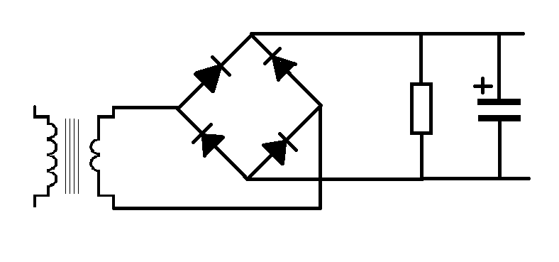
therefore a secondary coil output of 12 volts.

then there was the diode bridge, the forward conduction voltage for a diode is 0.7v this leaves up 11.3volts.
the load of the circuit was 1200Ohms.
and the smoothing capacitor in the circuit was 1 Milifarad

we ignored the diode voltage drop and said that the ripple current was 0.2volts saying that this means that the voltage would ripple between 11.8 and 12 volts.

well, actually it ripples between 11.1 and 11.3 volts because there is a voltage drop in the diodes.

Lets fact it, what good is 11.3 volts. have you ever seen this as the supply needed in a circuit?
What is we really wanted 9 volts.

Well, where do we want the ripple to be, between 8.8 and 9, or 8.9 and 9.1, where am I going to find a transformer that outputs 9.7 or 9.8 volts, so that I can satisfy the voltage drop across the diode and the ripple current and keep enough energy for my circuit? to put it simply, nowhere.

What if I were using germanium diodes, now I need a 9.3v output.

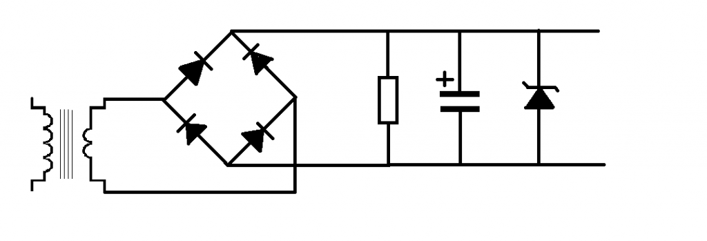
What we use in this situation where we want the power supply to be at a specific set voltage is a zener diode.

The zener diode sits across the positive and negative power supply rails.
in this case we'll stick with out 12v transformer, and use a 9v zener diode.


 What this means now is that whenever the voltage is above 9v the zener diode will conduct, meaning that the supply voltage will fall, but if the voltage were below nine volts then the zener diode would not conduct and the supply voltage can rise.


An even better alternative.
An even better alternative to using zener diodes is to use a voltage regulator.

These components have three legs.
the first leg is the input, this connects to the positive rail of the power supply circuit.

the middle leg is the ground leg, this connects to the ground of both the power supply circuit and the zero volts rail of the circuit that you are powering.

The final leg 3 is the Vout leg, this connects to the positive power rail of the circuit that you are powering.


Common voltage regulators are the 78 and 79 series.

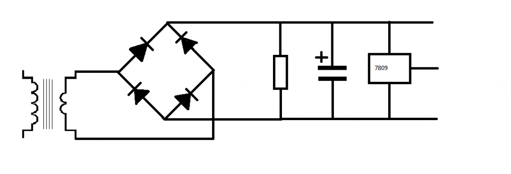
the 78 series are positive, you apply positive voltage to the input leg and a positive voltage is returned at the output leg.

The part numbers relate to the output voltages:
7805 = 5v
7809 = 9v
7815 = 15v

the 79 series are negative voltage regulators, you apply a negative voltage to these and you get a regulated negative voltage out.

7905 = -5v
7909 = -9c
7915 = -15v

Monday, May 21, 2012

Electronics Lessons: More on Diodes

So far I only introduced the humble silicone diode, the one that we use for blocking voltage from travelling one way in a circuit.

there are many types of diodes, so I'm going to attempt a very quick round up of the three main diodes that have interested me:

Silicone diode:
the silicone diode was covered before, it has a high reverse breakdown voltage (i.e would not conduct in reverse unless a large voltage was applied to it), it's activation energy is 0.7 volts (it will not forward conduct until this time.)

The way in which the diode goes from non-conduction to conduction is rather like a transistor, there is a curve that is centred around 0.7 volts

Germanium diode
The germanium diode is pretty similar to the silicone diode, however it is a lot older. it still has a high reverse breakdown voltage (though not as high as a silicone diode, but it's activation energy is lower at a mere 0.3 volts.
The conduction curve for the germanium diode is centreed around 0.3 volts

Zener Diode
the zener diode is a little weird, it's symbol is the same as a regular diode, except with the edition of a flare on either side of the bar in the symbol.


What makes a zener diode weird is it's breakdown voltage figures and behaviour


For a silicon diode, once the breakdown voltage for the component is reached that's it, the diode gives up, it conducts in forward connection and reverse connection, it's more like a piece of wire than a diode, or maybe a resistor. but certainly not a diode.

A zener diode has a very specific breakdown voltage, (of say 9 volts) and it recovers from this too! so that it only conducts in reverse when the voltage applied to the positive side of the component is above the breakdown voltage.


Monday, May 14, 2012

Simple Circuits: signal mixers

A couple of weeks ago I introduced a new component in an "electronics lessons" post, that component was the op-amp, since then I introduced the idea of using it as a level meter.

I've kind of stayed away from saying here's an amplifier, because, simply, I already gave the circuits, inverting/non-inverting, there you go, pick resistors to set the gain and build voila a simple amplifier.

What I'm going to look at in this lesson is an amplifier that's a little more complicated.


Summing amplifiers

Summing amplifiers are essentially amplifiers that take a signal and produce it's sum.
they are inverting amplifiers so bear in mind that the sum is negative, and would need to be flipped by a final amplifier.

If you take an example amplifier with two inputs:
The voltage on input 1 = 1, and the input on input 2 = 5, we'd expect the output of the amplifier (assuming gain=1) to be -6, 1+5 = -6 (minus 6 because it's inverted)

Resistor networks
As you may have guessed the output voltage of the summing amplifier is dependant on a network of resistors, and (yay) more maths...

the voltage at the out put is

Vout = -Rf ((v1/v1) + (v2/r2) (and so on))


so in the above example of a summing amplifier with two inputs.
if we make all the resistors 10Ohms we have

v out = -10 x ((1/10) + (5/10))

vOut = -10 x (0.1 + 0.5)
vOut = -10 x 0.6 = -6 (just like in the above example)

if we have three resistors the equations will be

vout = -Rfeedback x ((v1/r1) + (v2/r2) + (v3/r3))

The summing amplifier is infinity expandable, and is a critical component of a mixing desk.
an 8 channel mixing desk is simply an 8 channel summing amplifier.

Loud switch

Lets assume that we have a two channel amplifier.
the voltages at input 1 are both 1volt signals.

R1 = 10Ohms
R2 = 10Ohms
R3 = 5Ohms
RF = 10 Ohms

There is a switch that will select wither the 5 or 10 Ohm resistor for V2

the output looks like this

Vout = -10 (1/10 + 1/10) = -2

and when the "loud" switch is pressed on channel 2 it looks like this

Vout = -10 ( 1/10 + 1/5) = -3

that 3 volt output is made of 1 x v1 and 2 x v2 so we see the signal on channel 2 (that is V2) now appears twice as loud as the source attached to V1


Monday, May 07, 2012

Red light torch (update from earlier project)

So a long time ago I posted a project that loosly described how to take a handfull of red LEDs and put them into a torch.

http://ah-screwit.blogspot.co.uk/2011/06/led-torch-with-difference.html
The idea being that, when you are out at night, if you want to preserve yuor night image then you need as much rodopsin in your eyes as possible, and light bleaches rodopsin, well, most light does, but red light does not.

Which is why you want a red torch to look at stuff when you're out at night as then you can preserve your night vision.

This post is just an update of that project, to show some pictures of the modified torch, and the modified torch in use.

After a while it because clear that this torch was just a bit big and bulky so a new LED torch was made.


Original rechargeable torch from woolworths:

At the start is has a light bulb, which has been replaced with a cluster of LED lights, angled to point towards the reflector:

It's a little more impressive in the dark:

Especially for illuminating star maps when using a telescope at night:


Slimline Torch
After a few months of use it became clear that the old torch was big and bulky, having it in a pocket took up any space that could be being used for keeping sweets or gloves. so a new LED torch was made.

The body of the torch is a white LED torch/cycle light. this is the perfect donor torch because it's largly already setup for use with LEDs.

start with the torch:


you'll need 5 regular brightness LEDs (super bright will take away the point of having a dim red torch to preserve your hight vision:


Take the reflector and lense off of the torch, (this is how you change the batteries)
now using a solding iron remove the white LEDs from the circuit board. -be sure to note their polarity!


Now add the red LEDs to the board, again be sure to note the polarity

Finally test your new torch:


The costs for this project are as follows:

LED torch = £1 it came from poundland, for people overseas poundland is a stock surplus type store where everything inside the store cost just one pound.
5 x LED these are a few pence (because I buy them in quantities of hundreds at a time from Rapid Electronics.

The batteries came inside the torch and so are included in the original pound.

All in all the total price is not more than £1.10