Showing posts with label Ohms. Show all posts

Monday, June 11, 2012

Electronics lessons: Music effects: The distortion pedal

This is the first guitar pedal that I eve made...

What is distortion.
Distortion is the changing of a wave form from one form to another so as to distort it.

Technically speaking, a tone control distorts the signal, a envelop filter distorts the signal, anything that "colours" the signal also distorts it.

but if I stop being a smart ass for a second.

distortion to most people means fuzz.

History of overdrive.
It seems to make sense to me to start at the very beginning, and lets take a look at the physics of what's happening.

Many people try to make a distinction of what type of distortion they are listening to, if it's a hard clipping, or soft clipping, some people thing that an over drive and a distortion are different, they kind of are, but fundamentally it's all the same.

OK, distortion was around long before this, but lets set the scene...
To understand this analogy you;re going to need to know what a green back is.
A green back is a speaker made by the British speaker manufacturing company Celestion in the 60's or 70's.
It was a basic run of the mill speaker, which has gained cult status (and price) with it's inability to handle the power of the signals that people were trying to drive thought it.

Now you might think that from the description above of a basic speaker that's gained notoriety for sounding bad might make you think that I dislike it.
nothing could be further from the truth. the point I'm getting at here is that the magic sound of 60/70 British rock, (think Rolling stones/Yard birds/Led Zepplin) lays a lot in the mechanical and electrical limitations of the time.

Consider how a speaker works,
a coil of wire is suspended in a permanent magnet,
the coil of wire is subject to an electrical current, this makes the coil magnetic, where it will be either attracted to, or repelled from the permanent basket on the back of the cone.
the coil has a paper cone attached to it.
as the coil moves the paper cone moves, this moves air particles, which vibrate through the air and then the air vibrates against our ear drums and happy days we hear sound.

So we get that the coil is moving, and we get that we can turn the volume up and make it move more, but, the coil is attached (with what's called suspension) to the metal frame (spider) in the speaker construction. The size and stiffness of the suspension limits how far that speaker cone can move.
that means that for very large wave forms the speaker will not replicate exactly what is being asked of it.
it tries to reach the point where the signal applied it telling it to go, but excersion limits are met and the speaker cannot move any more.
additionally the suspension on the speaker slows down the cone as it reaches the excursion limit

So the following picture hopes to show you what I mean, I've drawn it on it's side so you can visualise a speaker cone going in and out.
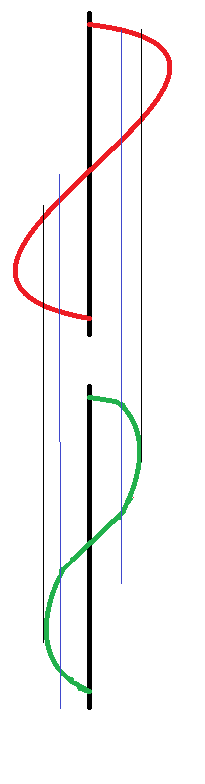
The thick black line is zero, this is where the speaker normally rests.
the red line is the input to the speaker.
you see it rising, the green line (speaker position) moves with it, then we reach the blue line, this is nearing the excursion limits for the speaker, so whilst the red line continues to move, the green line is being slowed by the suspension of the speaker.

The red line continues to rise where it meets the black line, this is the excursion limit the speaker can no longer move at all past this point whilst the red line continues to be at this point the speaker sits as it's maximum excursion position waiting for the red line to fall.

This is, in the most traditional sense an over drive distortion.
the wave is quite smooth, (as the suspension prevents square edges to the sound wave) and as such will sound like a warm fuzz.

It is also possible to get over drive distortion from an amplifier.
Consider the following chart.
the blue wave is what we want. the red wave is what we get
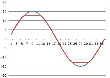
lets say we have an amplifier with supply rails of +15 and -15 volts, you we give the amplifier a 1v / -1v signal and say, amplify that, and set the gain to 15.

What should come out of the amplifier is a smooth wave (the same as went in) with peak values of + and - 15 volts.
but we can't actually drive the amplifier to the supply rail voltages, the most that we could get out is +13 and -13 volts, so the top and the bottom of the votlage is cut off.

This is a much harder clipping sound.

Now that we've listened to loads of music and realised that the classic hot sound of the 60/70s is so desirable what can we do to emulate that?
(clearly we don't want to run our amplifier at that level forever, and the amount of power that you need to put into a speaker cone to reach cone excursion limits makes your show loud, (and perhaps not suited to the venue size you have!)

So you want to fake it.


Well, now that we know what we're trying to fake, it's a very simple matter of finding a way to cut a little from the top and a little from the bottom of an audio wave.


So what we want to do is take a small wave form say 1 or 2 volts then shave a small amount of voltage off of it.

So what we want is a component that can give a low resistivity for small signals, and gradually that resistivity will increase until it hits a limit then it will only allow that amount of signal to pass.
kind of like some kind of flow control.


well, we don't exactly want flow control, but if we look at the diode we have the component that we need.

the following graph shows the voltage and current flow of a regular silicone an germanium diodes as they approach their forward conduction zones:
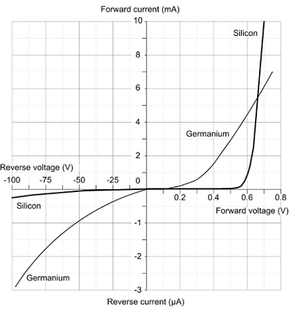
You see that (especially with the silicone diode) there is a gently slope on the voltage vs current graph, this is that component gradually decreasing it's resistance to a signal, until it reaches ~0.65 volts where it begins to conduct, at 0.7 volts the junction inside the diode is saturated and it's in full conduction mode.


So what does this mean for our distortion effect.

Well, quite simply, we wanted a component that we could use to clamp our voltage inside an artificial set of parameters that would mimic the gentle slowing due to suspension and then flat constraint of an over driven speaker. and with a diode we actually have that.


There are two ways of using diodes in a distortion circuit, these are often called hard and soft distortions.
what makes a distortion hard is very angular edges on the wave form when it flattens off, (see the picture of the amplifier distortion above, and soft distortion is more controlled, the distortion still exists, but it's smoother.

not only does the wave look smoother, but it sounds smoother too!.

There are two ways to use diodes to produce this distortion.

First we need to understand the building block that we're using.

two diodes are placed back to back, (and front to front)
this looks like a crazy way to put a diode,-surely they'll just conduct to ground regardless of the signal applied and there will be no output?

Well, no they won't just conduct to ground because as explained above, as the diode is switching on it has a resistance, and even when it's on there is a voltage drop.

So what actually happens is we clamp the signal line to only permit signals within a certain threshold, and limit any larger signals to that threshold.

So now we have a simple model.

for signals under 0.5 volts a diode acts much like an open circuit,
for (silicone) 0.5 - 0.7 volts a diode acts like a resistor with progressively less resistance being applied as the signal rises
for germanium diodes 0.2-0.3 volts acts like a resistor with progressively less resistance being applied as the signal rises
for signal over 0.7 volts the diode acts like a short circuit grounding the circuits and therefore clamping the signal to the activation energy threshold.


now that we have this component block figured out we can look at how to apply to to a circuit.

The first method of connection is to follow the amplifier that is used in the circuit with the component block.
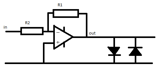
This literally clamps the output to 0.7v, this type of circuit arrangement is suited to either Light emitting diodes or germanium diodes.
the use of silicone diodes produces a quiet hard clipping in this position, mixing a silicone diode and a germanium diode in series for the block can have a positive effect in making this clipping less harsh.


The second way to use this component block is in the feed back network of the inverting amplifier.

we put the network in parallel with the feedback resistor.
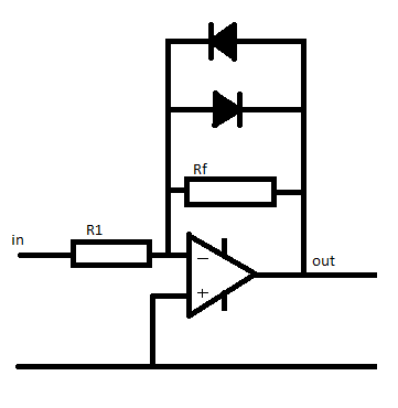
At low signals the diodes act like an infinitely large resistor.

so the value of 1/Rfn = 1/Rf + 1/diodeR(infinity) therefore the total value for the resistor network (Rfn) equals Rf

so if R1 = 100 Ohm, and Rf = 200 Ohms,
Gain = -Rf / R1 so the gain = 2

now as the signal gets larger the amplifier will put out a larger signal, when the output of the amplifier reached 0.55v the diodes are behaving like a resistor.
we'll (for the sake of simplicity) say that the value of this acting resistor is 200 Ohms.

now the feedback network has a resistivity if found by the equation
1/Rfn =  (1/200) + (1/200)
so Rfn = 100 Ohms

now the gain of the amplifier is
Gain =-rf/R1
gain = -100 / 100 = -1

so the gain has gone down.

Now the voltage continues to rise to above 0.7 volts, the diodes now act like short circuits.

the resistance of the feed back network a 1/Rfn = 1/200 + 1/0  so Rfn 0

and the gain is
-0/100 which also equals zero.

Remember a gain of 1 is unity.
the output = input x gain.

so a gain of zero actually turns the output off completely.
(but if that were to actually happen the there would be no voltage so the diodes would have infinite resistance again.

thus the voltage is again clamped in the region of the diode conduction threshold.


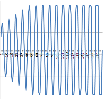
You can see in the graph below what a gradually increasing waveform looks like as it approaches the clipping region.
at the start there is no distortion, as teh wave gets gradually larger the clamping effect of the distortion begins to take effect, you see by the end of the graph the distortion is no longer smooth, the input signal is massive and the clipping is more and more choppy (and will sound worse)

Tuesday, August 23, 2011

Electronics Lessons: The Resistor Standard Values -The E12 Values

In the transistor amplifier lesson I introduced a new concept without talking about it too much. I kind of just shoved it in there and assumed that you'd get to know what I was talking about.

If you found it confusing or didn't have the foggiest what I was talking about, then read on.

Standard Values
Standardising the values allows manufacturers to make a handful of components, in bulk quantities, therefore keeping costs down.

Can you imagine the size of the hobby section in electronics shops if every component value imaginable was actually made? 1oh, 2 ohm, 3 ohm, etc or 1 and 1.1 and 1.2 and 1.3 and 1.4ohms all the way up to millions of ohms?

Instead of making every size imaginable, the manufacturers use standard values instead.

This values are spaced in the same kind of range of values as notes on a piano, (white and black).
in an Octave, there are 7 white keys and 5 black keys.
C, C#, D, D#, E, F, F#, G, G#, A, A#, B then we get back to C
Those notes are all equally spaced apart and the gap between then is called a semitone.

Standard resistor values have the same sort of spacing, the spacing between them is 10^(1/12)
(or ~1.212). (there are, just like on a piano, 12 values in a range, and the ratio of the spacing of these is equal.)

This is why it's called the E12 series (there are 12 values in the series)

The values
This makes values that start a 1,
then (multiply by 1.2 = 1.2), x1.2 = ~1.5

Therefore the actual values are

1, 1.2, 1.5, 1.8, 2.2, 2.7, 3.3, 3.9, 4.7, 5.6, 6.8, 8.2 and 10 (the ten is the start of the next range, kinda like how that C was the start of the next scale on the piano.)

Designing
Of course this is a bit of a trouble, when we're designing circuits we often come up with values where there just isn't a standard value.

In the amplifier lab none of the values were standard! all had to have a closest fit.

However, when you look at the range of values, it's not all that bad...

Margins of error/Tolerance
If you look at the values, they are all equally spaced, with not more than 20% between the values.

The gap between 5.6 and 6.8 is 1.2Ohms, so lets hit exactly in the middle, and say that you need a 6.2Ohm resistor.

If you go for a 6.8Ohm, resistor you're 0.6Ohms over,
If you go for a 5.6Ohm resistor you're 0.6Ohms under.

In short, whichever way (up or down) you go, you're only ever going to be 10% or less out of what you want the value to actually be.

I suppose you could say that 10% is a large percentage and does makes a difference.
You would of course be right to say that.

But consider two things, firstly, your designs, are mathematical models, not measured values,
And that even the values on the data sheet, though they are measured values, they are measured from a sample, not the component that you have in front of you, -hence data sheets provide minimum, typical and maximum values, measured from a range of samples.

Whether you chose a higher or lower value depends what you're working with, if you're getting close to the absolute maximum values of current, then choosing a lower value, and possibly exceeding that absolute maximum would not be a good idea. However, if you're well within the absolute maximum, then choosing a slightly lower value of resistor isn't going to cause too much current to flow, nothing is going to fail or melt!

Also, you should remember that if you desperately need an exact non standard value, you can add resistances together.
if you need exactly 45Ohms, no more no less then instead of settling for 47 ohms, use a 12 ohm and 33 ohm resistor in series!

Also remember that on resistors there is a tolerance band.
If you're using a silver tolerance band then your components may be as much as 10% out of their marked values anyway!

Thursday, August 18, 2011

Electronics Lessons: The Transistor Simple Circuits 2 (Lab 3)

Now that we've looked at resistors, transistors, and capacitors. Lets see if we can put them to some use to build another really simple circuit, this will be a bit more complicated than using the transistor as a switch.

Lets start by build an amplifier;

I don't expect that you know how to design the amplifier yourself (that's why you're here?), so I'll hold your hand all the way through the design process, we'll be using at least one of the components in a way that I haven't described that it could be used like that yet, so there will be a little deviation to describe that, but hey, this is only lab3 and you're already building something pretty cool... you know the components from the past 5 lessons, and you're aware of one of the building blocks that we'll be using from a past lab lesson (lab 1).

Perhaps the holly grail of all analogue circuits is the amplifier, I don't know why if I'm honest, but just about everyone seems to want to know how to make amplifiers, and those that do know how to make amplifiers, well, in spite of the maths involved seem to get a kick out of making them, and even those that shy away from the maths have a really good go following reference circuits.

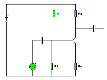
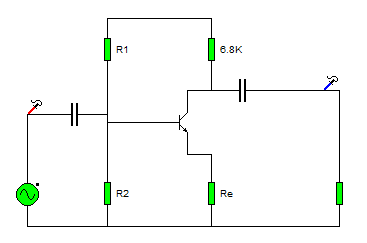
This is the first amplifier circuit I was ever introduced to:

Common Emitter Amplifier
The last amplifier that we looked at was an emitter follower or common collector amplifier, that's a device that amplifies current, whilst leaving voltage unchanged, we used that to boost the amount of current available from a low power source so that we could turn on a light.

The amplifier that we'll be looking at now doesn't amplify current, it amplifies voltage.
The first thing to do is introduce you to the circuit.

Firstly, lets break the circuit down,
The little round thing with the waveform shape in it is a signal source,

For this demonstration we'll set the output of the generator to a sine wave, with a frequency of 1KHz and we'll set the amplitude (size of the signal) to 1v.

This means that the waveform outputted by this generator is:
A nice curvy wave form, that is modelled by the math function sin(x).
It goes between +1v and -1v.
And it does this one thousand times a second (a complete cycle take 1millisecond -1ms.)

The next component we see is a capacitor, in the lesson on capacitors I talked about the capacitor acting like a storage tank for electricity, saying that you could charge a capacitor and discharge a capacitor, here we are using a different property of the capacitor, it's ability to block DC (direct current) signals, and allow AC (alternating current) to pass.

The reason that we want to use this is because we need to set a bias on the transistor so that it's working in a linear region, -don't worry about that for now, I'll explain more later, right now we'll look at the DC blocking capabilities of the capacitor.

When we use a capacitor like this it's called a coupling capacitor.

Coupling capacitors
The problem with the signal source that we have is that it's waveform is centred around 0volts.
fair enough the transistor will turn on then the voltage rises above zero volts, but when it's in it's negative half of the cycle (or anywhere in the cut-off region), the transistor won't be conducting at all. So we need to move the centreline of the wave form up so that it's centred around a positive voltage, that'll let our transistor work in a region where it's on a little right up to on a lot, (remember how we talked about the transistor as a variable switch? now we're going to use it as a variable switch.)

Before we introduce the transistor into the mix we'll look at how we get that wave form to climb up to a more positive voltage using coupling capacitors.

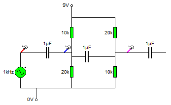
The diagram below shows some things that should be familiar to you from lab 1.

Ignore the capacitors and signal generator for now.
There is a positive voltage source (+9v) and a zero voltage source (0v) (just like the battery terminals.) And there are two resistors set up as a potential divider, followed by two more resistors set up as potential dividers.

Using the maths learned in Lab 1 we can see that the voltage at the blue probe is 6v, and the voltage at the pink probe will be 3v. -remember Vout = (Z2/(Z1+Z2)) * Vin)?

So we know that there is a DC voltage of 6v at the blue probe, and a DC voltage of 3v at the pink probe.

(now we'll include the capacitors and signal source again).

The resistors used are significantly high enough to not interfere with the source when the AC signal is introduced.

Reading from left to right.
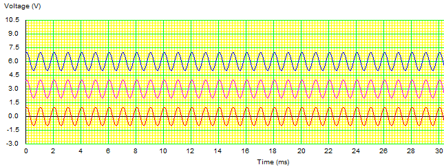
The first red probe, measures voltage a +/-1v centred around 0v.

The capacitor then blocks any DC voltage going to, or from that point in the circuit moving onto the next point, (blue probe).

If there were no DC component here we'd measure +/- 1v centred around 0v, however, the potential divider here means that there is a 6v DC voltage at this point, so that +/-1v is superimposed on this 6v source. meaning that the wave form is now alternating between +7v and +5v (+/-1v centred around 6v).

Moving a little further on there is another capacitor that stops this +6v DC component from moving to or from any other part of the circuit. Here we reach the pink probe.

Now the wave form has had all it's DC component removed and is once again 0v +/-1v.
but our potential divider has set a DC voltage of 3v onto this part of the circuit. So once again the AC voltage is superimposed on the DC voltage giving a wave form that's +/- 1v centred around 3v (+4v to +2v).

Here is what the wave forms are looking like at each part of the circuit.


Biasing
I suppose that the first question that needs to be answered is Why do we bias amplifiers. I gave a pretty poor description above about the fact that it doesn't turn on on the negative half cycle of the input wave, (and that is true).
but to answer the question properly again we're going to need to look at the data sheets for the component again.

Lets take a really simple (and now really rather old transistor, the BC108).

http://www.datasheetcatalog.org/datasheet/MicroElectronics/mXuvuyv.pdf

As before there are a couple of important things to look at in the data sheet.

The first is Base - Emitter voltage (Vbe) you can see that this is 0.6v

Next look at the gain value of the transistor, (this is called hfe) this is (for group A components typically 170).
this large hfe value means that we know that the collector current is much much larger than the base current.

so Vbe = 0.6
Gain = large
Ic >> Ib
Ie = Ic + Ib

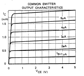
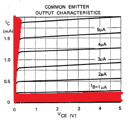
You'll find a graph in that data sheet called "output characteristics",
The output characteristics these define the voltages that you need across the device to make it work in a region called the linear region, this is the region where the device is going to amplify small and large signals equally without distorting either.
There are several lines on the device, all are in a shape that goes up at the start, and has a sharp knee, then settle into a straight line, the different line correspond to different base currents.

On the graph below I've marked two areas in red, you want to stay out of these regions because either the transistor is off or behaving in a non linear way (very on), (the one closest to the X axis is the cut off region) and the one closest to the Y axis is the saturation region.

The first thing that you're going to need to determine is the Resistor RL, this is the load resistor for the amplifier,

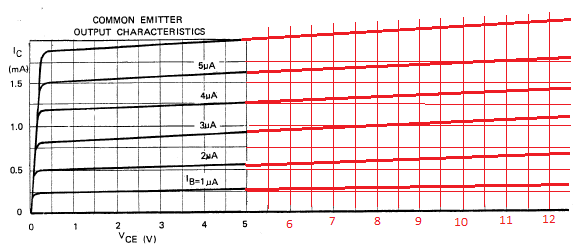
First, you're going to need to extend the graph so that we can see it working inside the voltages that you're working with, (the x axis only goes up to 5v, and we're going to use a 12volt supply).
(I'll assume by now that you've murdered an ATX power supply and therefore have a 12v supply (and are no longer relying on 9v batteries).

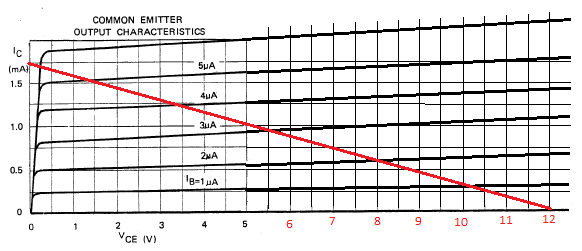
Now you need to draw line on the graph between the point the you want to set as ICmax, (on the Y axis, and your supply voltage (Vcc) on the X axis.

Set your ICmax somewhere below the highest marking on the chart, I've chosen 1.75mA

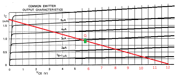
This new red line is called the DC load line, and in the middle of this line is a point that's at the middle of the linear operating region of the amplifier, this is the quiescent point, or Q point.

You can see the green dot in the middle, set at around 5.8v (you might also be realising that this is not an exact science!)

Right... so what we know now is:

Ic(max) = 1.75mA
and Vcc = 12
Vce(q) = 5.8
Ic(q) = 0.9mA

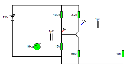
We need to make a decision now as to what we want the voltage of our emitter to sit at, some guides suggest splitting the voltage equally between the Rc, Rb and the transistor itself, however, I think that setting Vre as 1v doesn't seem like a terribly bad thing to do! -you could chose a different value.

To find a value for Rc
We use the forumla

Ic(max) = (Vcc - Vre)/Rl

0.00175 = (12 - 1)/Rl

Which works through to give us the equation
Rl = 11/0.00175 = 6285
The closest standard value is 5.6K or 6.8K

It'll be perfectly fine to use a 5.6K this will increase your IC(max) value, but you're still far below the absolute maximum rating given on the first page of the data sheet. the higher the voltage here the more restrictive you're being on the input signal voltages that could be used before the amplifier clips the signal.

The current gain of the transistor we know from the data sheet is 170

the gain is the value of the collector current, over the base current

hfe = Ic /Ib

hfe = 170 and Ic = 1.75mA
Therefore Ib = 1.75ma / 170 = 10uA


Given that we now know the values of Vre, Vbe and Ib we can start to set the bias of the base leg of the transistor.

To find the value of R2 we use the following formula.

R2 = (Vre + Vbe)/(10 * Ib)

R2 = (1 + 0.6)/10 * 0.00001)
R2 = 1.6/100 * 100^-6 = 16000 -15k is the closest standard value

and we can also figure out the value for R1

R1 = (Vcc -(Vre + Vbe))/(11*Ib)
R1 = (12 - 1.7)/(11*0.00001)
R1 = 10.3/0.00011 = 93636 - 100k is the closest value


Now we need to go about setting that emitter resistor Re.
We calculate this using Ohms law
We know that the emitter current is the sum of the base and collector current
Ie = Ic + Ib
Ie = 1.75ma + 10uA
Ie = 1.76mA

We know that Ohms law says V/I = R

Vre / Ie = Re
1 / 1.76mA
1/0.00176 = 568 Ohms (and the closest standard value is 560Ohms)

Earlier we talked about coupling capacitors,
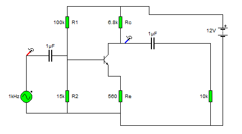
on that last amp circuit you'll see red and blue probes, this is what the signal looks like at those points.


Input vs. Output
Finally, let's move our probes to measure the input and output signals.


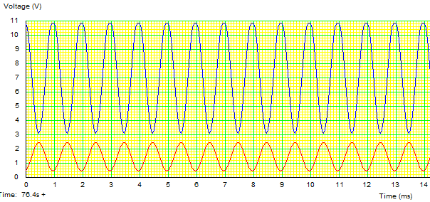
Look closely at that chart.

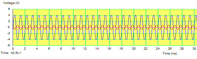
The red line is the input signal, and the blue line is the output. We see that the blue line is much bigger than the red line, but also notice that as the red line is going up, the blue line is going down.
This amplifier has switched this signal upside down.

This type of amplifier is called an inverting amplifier.

Gain
The gain of am amplifier is its output divided by its input.

remember the current gain of the transistor was the collector current, over the base current.
(actually it's emitter current over the base current, but since the gain factor is so large we assume that Ie is just about equal to Ic)

The voltage gain works the same.
The input voltage is +/-1v, (e.g 2v).
and the output voltage swing is +/- 4v (eg 8v)

So the gain of this amplifier is 8/2 = 4

The signal coming in is made 4 times larger.

Friday, July 22, 2011

Electronics Lessons: The Resistor Simple Circuits

Ok, so it's time to crack out the components and do some simple experiments.

Lessons are boring, I don't need to tell you that though. If you've read through the resistors lesson you may have switched off half way through, you may have just clicked away.

Endless theory is boring. So... lets crack out a few components and start making something nice and simple to illustrate some of this theory.

Equipment
For this lesson, you'll need
>a 9v battery
>a battery clip to attach wires to the battery.
>a small light bulb (and possibly bulb holder).
>and about 3 100ohm resistors, (brown black black).

If you have one then a multimeter that measures voltage would be good.

You should be able to nip into your local radio shack/Maplin/electronics hobby store and get all of these things for less than £5.

Method
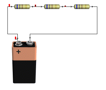
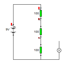
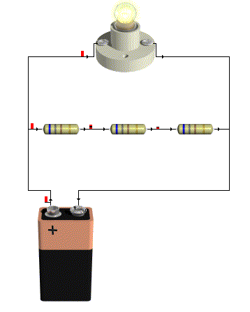
The first thing that you want to do is join the three resistors in series, and attach them to the battery, whether you practice your soldering skills, use a breadboard (as in the little plastic thing), just twist the legs together to form a connection or even use a breadboard with screws and screw cups to hold the components, if doesn't matter, all you need to do is connect the resistors in series and attached then to the battery.

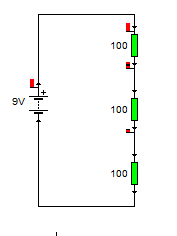
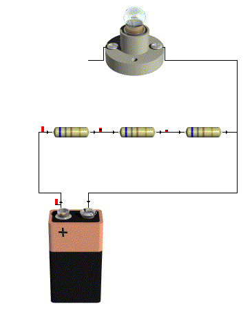
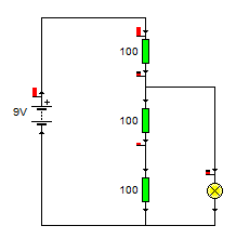
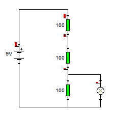
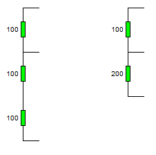
I'm going to illustrate this with a series of pictures, that should show you what you're looking at, and the schematic diagrams that represent what the circuit is.


Next attach one side of your light bulb also to the negative side of the battery.


Now you want to attach the other side of your light bulb to the positive side of the battery.
you should see if lights up very bright.


Now remove the connection from the light bulb to the positive side of the battery, and connect the battery to the second leg of the first resistor, you should see that the bulb still lights, just not as bright.


Now remove that connection and connect it to the second leg of the second resistor. the bulb should light a little bit, but it won't be very bright at all.

Extra Activities
If you don't have a multimeter then you should just skip over this bit to the results section.
Now take the light bulb out completely, switch your multimeter onto measure volts in the 20volts range, (or as close to 9volts without being under 9volts depending on your meter).

Touch the (usually black) Comm probe to the negative terminal on the battery and the other (usually Red) lead onto the positive terminal of the battery.

The display should read 9Volts,

Now touch the red lead onto the second leg of the first resistor, it should now read 6Volts.

And if you touch the second leg of the second resistor it should now read 3Volts.


Results
What you have created is a potential divider.
In an earlier lesson we talked about electricity as being a potential energy, (though not in the strict physics sense) this little collection of resistors is dividing up that potential so it reduced as you go down the ladder.
We talked about how power and voltage were linked earlier, the reason that the bulb shines less brightly when a lower voltage is applied to it is because there is less power going to the bulb to make it shine.

There is an equation to work out what the voltage at the given points of a potential divider will be.

That equation is

Vout = (Z2/(Z1+Z2)) x Vin

This formula is using Z in place of R, it may be a little confusing at first, but go with it!

I've made it a little more complicated using three resistors in the example, but that's ok, we learned earlier about how to deal with resistors in series, you just add them together.

Lets look the voltage on the second leg of resistor 1

We know that the input voltage Vin is 9v
The resistor R1 is 100Ohm, so Z1 = 100Ohm
but what's Z2, (yes if you look at the schematic R2 is 100Ohm, and R3 is also 100Ohm).

For this equation, since we're measuring at the second leg of R1, Z2 is the total resistance of R2 and R3 which are in series, (so we just add them together.)


So lets fill in that equation now.

Vout = (Z2/(Z1 + Z2)) x Vin

Vout = (200/(100 + 200)) x 9
Vout = (200/300) x 9
Vout = 0.666666666 x 9
Vout = 6

That's what we measured!

Now let's look at the voltage at the second leg of resistor 2,

This time Z1 is the top two resistors (R1 + R2) and it's 200Ohm
The voltage is still 9v
and Z2 is R3, which is 100Ohm

Vout = (Z2/(Z1 + Z2)) x Vin
Vout = (100/(200 + 100)) x9
Vout = (100/300)x9
Vout = 0.333333333 x9
Vout = 3v

Which again is what we measured! so everything is looking good.

Wednesday, July 06, 2011

Electronics Lessons: The resistor and Ohms law

I started to write a post on what is electricity, but soon realised that subject was far too broad, far to detailed, far to simple and far to complicated all at once...

Suffice to say, what electricity is doesn't matter so much as what you can do with it.

I'm going to create a series of blog posts as a kind of electronics 101, the idea being that anyone can start at the beginning, learn about components, and learn how to build up circuits.

Throughout these lessons I'll be making a series of good analogies, and bad analogies.

Resistors


Theory
In Physics things have potential energy when they are sat still, a weight sitting on top of a book shelf has potential energy, if you nudge the weight to the edge it'll fall off, that potential energy has been converted into kinetic energy.

For the purpose of a resistor, think of electricity as like a tank of water, sat on top of a hill, the electricity, like anything is itching to get to the ground, and will take the path of least resistance.

A resistor adds resistance to the flow of electricity.


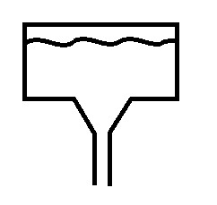
Look at the two pictures, the first shows a tank of water with a small opening, when you think about it you'll see that in this case the water will run down slowly, the narrow channel adds resistance and stops the water just gushing out.

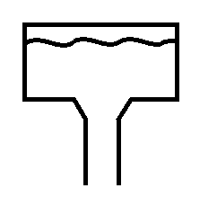
The second picture has a bigger opening, in this case the water just gushes out, you can't stop it because the channel is too wide, the water gushes out with such force that you couldn't just put your hand over it.

There are calculations that you could do, knowing the size of the header tank and the size of the outlet to know with what force the water is pouring through the hole.

In electricity, the size of the header tank is measured in Volts, the size of the pipe or opening is measured in Ohms, and the force that the water pushes is not measured in PSI but is measured in Amps.

Resistance, Voltage and Current
The equation is simple.

The voltage, divided by the resistance is equal to the current.
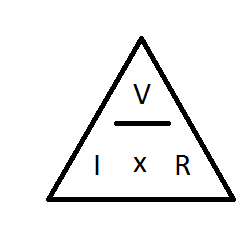
V/R = I
so say you have a 9v battery, and a 100Ohm Resistor.
9/10 - 0.09A (or 90mA)

Next you might be thinking about about how much power that actually is. (if your resistor can't handle the power it's get hot and fail, sometimes quite spectacularly.)

Voltage, Current and Power
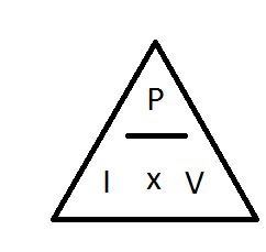
Another electronics law tells us that Power = Voltage multiplied by Current
In the example above the voltage was 9V, and the current dissipated was 0.09A

9 x 0.09 = 0.81W

Now less than 1 Watt doesn't sound like a lot, but consider that resistors generally come in 1/8th Watt, 1/4 Watt, 1/2 Watt, you're going to need at least a 1Watt resistor, so it's going to be reasonably large.

Resistor values

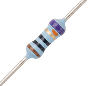
Resistor values are quite easy to remember, once you've been told what the values equate to.
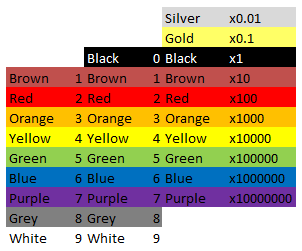
black is zero and brown is one, after that the colours follow the colour spectrum, Red, Orange, Yellow, Green, Blue, Purple, then Grey and white are tagged onto the end. quite why it was done like this with black and brown first, and not just the spectrum colours first then extra ones I don't know...

Anyway,

Black = 0
Brown = 1
Red = 2
Orange = 3
Yellow = 4
Green = 5
Blue = 6
Purple = 7
Grey = 8
White = 9

The last band on the resistor is always Silver, Gold, Brown, Red, Green, Blue, Purple or Grey, these colours relate to the tolerances. (how far off of the stated values the component might be).
Silver = 10%
Gold = 5%
Brown = 1%
Red = 2%
Green = 0.5%
Blue = 0.25%
Purple = 0.1%
Grey = 0.05%

So, if you have a resistor that has colour codes

Red, Red, Brown, Silver
the values are
2 2 * 10 = 220Ohm, +/- 10% -i.e the value is somewhere in the region of 220 Ohm, 198 Ohm - 242 Ohm range (quite a range.)

You might notice that black is missing from the first column, and be thinking how do you write 1Ohm, this should be Black, Brown, Black right? (01 x 1)

Wrong, the correct way to write 1 ohm, is Brown, Black, Gold (10 x 0.1)

Symbols
Resistors, like all components have a symbol user to indicate them on electronics schematics.
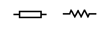
the symbol for a resistor looks like a box (the box does not have a line through it) however you may sometimes find the symbol written as a zig zagged line.

So that about wraps up the humble resistor. There is of course more to learn, there is indeed always more to learn. I'll cover some more advanced stuff with resistors, and the different type of resistors later.

Calculations
As with everything electronics related, sooner or later you run into something maths related.

Even with the simplest of components, maths somehow finds it's way in.
Not to worry though, the calculations concerning resistors are really simple.

Resistors in series
This is as easy as one add one.

When resistors are in series (one linked to the other like a train) you just add all the values together.

R1 + R2 + R3 + ... + Rn = Rtotal

In the circuit above there are 4 x 8Ohm resistors.

8 + 8 + 8 + 8 = 32Ohms.

Resistors in parallel
When you connect resistors in parallel, things get a little more complicated, a mathematician would tell you that it's the sum of the reciprocal of the values of the resistors that makes the reciprocal of the total resistance.

And they would be right, but they'd also likely confuse the hell out of you.

In laymans terms, it's the sum of one over the value of all the components, that makes one over the final value, 1 over this value gives you the total resistance.
(1/R1) + (1/R2) + (1/R3) + ...+ (1/Rn) = 1/Rtotal

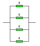
In this circuit the resistors are all arranged parallel to each other and connected differently from the original circuit.

The sum for creating this circuit is

(1/8) + (1/8) + (1/8) + (1/8) = (1/total)
1/8 = 0.125

So writing this out a bit more long hand we have...
0.125 + 0.125 + 0.125 + 0.125 =(1/total)

If you add all of those together you get 0.5
And 1/0.5 = 2

The total resistance of 4 x 8ohm resistors in parallel is 2 Ohms.


Series and parallel connections
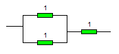
Sometimes you're going to want to connect things in a mixture of series and parallel.

You might do this because you want a 1.5ohm resistor, they don't make these but you could connect 2 x 1ohm resistors in parallel

1/1 + 1/1 = 2
1/2 = 0.5

Then add a third 1 ohm resistor in afterwards in series and you get 1.5Ohm.

You might want to do this for a completely different reason than getting values that you can't get...

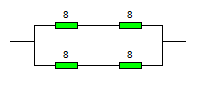
look at this example:

To start with break it down into two halves.
there's clearly a top half (2x 8ohm resistors) and a bottom half that's the same.

So work out the values of those first.

Top half = 8 + 8 = 16 Ohms.
The bottom half also is 16Ohms.

Now they are in parallel to each other
( 1/16) + ( 1/16) = 0.125
1/0.125 = 8

Now you may be wondering why anyone would be such a sadist as to use four components, have to go through that maths when they end up with the same value as just one of those components.

And the answer is power, as in power handling.
If you have a wire that can conduct a certain amount of power (voltage and current), and if you exceed that it'll heat up and melt, then you want to get a bigger gauge wire, you're adding more strands of wire, more paths to go down.

In the example above imagine that they were 10W resistors, but you needed to be able to handle 20W of load, buy arranging two side by side you've doubled that power handling capability to the 20W that you want.

but you've also halved the resistance, so then you add a couple more resistors in series to increase the resistance again.