Monday, April 29, 2013

Filing, -photographing documents en-mass

Filing is something that I'm both good at, and bad at.

There comes a point in most peoples lives when they are quite literally bogged down with paper. from bank statements, credit card statements, phone bills, TV bills, water and gas bills, old insurance documents...

All pretty important stuff important at the time to keep in case of dispute, and important later on as an aid to memory, (like remembering how much something cost when you bought it!)
having a receipt past the warranty period seems silly. But given a few years ago my house was robbed and I lost several possessions, it now seems worthwhile keeping receipts for things, just in case the worst should happen and I end up in the position again of trying to remember, exactly what model of tool did I have...

Because -let's face it. with an expensive tool like a welder you don't want to say I had a 260Amp MIG welder (when in fact I had a 150 Amp welder), if the original items were ever recovered you'd have some explaining to do as to how you claimed for something that you just didn't have! on the other hand, you don't want to err on the side of caution and say I think it was the 90Amp model, because then you won't have the same tools that you started off with.

So, it seems logical to scan or photograph documents.

To that end on Sunday I had a filing day. a day where I take the large bag of bills, bank statements and receipts that I've let pile up over the past few months or year and commit them to a digital format. Rather than scan them as I have done in the past this time I decided that I'd photograph them as this would be faster.

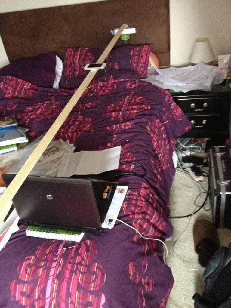
So I rigged up a little ledge to put my phone on such that it was at a distance that a single letter would fill the photo taken.

This involved a length of wood which I balanced on top of a few items with my iPhone sat on top of it. to take a photo I could just press the screen, and then move documents into view, press, put another document in view (on top of the previous letter so I didn't even need to fiddle with the document to align the letter in the phone screen), then press the take photo button.

It ended up as a pretty slick process, I got a whole ream of documents, (yeah actually 500!) scanned in a few hours.

The only think left to do is sort them into folders:
(for example my bank statements are sorted into a folder called bank, and they are named by the date the statement was sent. yyyy-mm-dd that way when sorted into folders they appear in chronological order and can be viewed sequentially.)

Here's a picture of the make shift camera holding set-up that I used to speed up the photo taking process.


Monday, April 22, 2013

Making a new hotend heater

Annoyingly my replacement hot end for my solidoodle has failed again. it did last a lot longer than the original hot end that came with the machine, but it was fairly obvious that it would fail again.

The mode of failure is that the nichrome wire is getting too hot and melting through the Kapton tape, this is turn is making short circuits, and reducing the heater resistance, this is making more current flow, and the power to the heater is increased, I'm seeing a lot of max temp reached where the hotend starts to peak well in excess of the max temp permissible, (the max temp is to protect the peek)

But also the sudden rushes of current cause cause the power supply to stall, I've had steps being skipped, sometimes I've had axis appear to just re-home themselves, so instead of a single layer skipping, the entire model will just move two inches to the left have way through a print.

So this time I'm going to go all out and create a new hot end.

I'm going to base my design on the Jhead style heaters, with a block close to the nozzle, but instead of using a resistor I've decided to use a small ceramic heater.

Instead of tying my heater and barrel to the nozzle (which I may want to change to have greater or smaller nozzle widths) I'm going to stick with the M6 barrel of the solidoode, I'll stick with the removable nozzle, and I'll make a heater that can be screwed on and off just like the heatcore design could.

To start with I've located a 40w ceramic heater online that comes in a 23mm long 6mm diameter tubular package.

This will be my heater.

My block that will be used to store heat will be aluminium, (it's easy to acquire, relatively cheap -at least cheaper than brass)

The block will need to be at least 20mm wide to accommodate the 23mm heater, (it will not matter if 1mm sticks out either side -and this will help keep the wires away from the hot metal.
the block will be 10mm thick, this should mean that there is 2mm either side of the heater,
this will also allow for a 3mm hole to be drilled to install a grub screw to hold the heater cartridge in place.

The heater will be 2mm from it's opposite side of the block, and 2mm from the barrel of the machine, the barrel is 6mm wide, here will need to be at least 2mm on the opposite side of the heat block, (therefore the heater block must be 20mm x 10mm x 18mm, the most convenient size is 20mm x 20mm x 10mm)

Lastly the thermistor must also be installed in the printer, and must be thermally bonded reasonably well, to achieve this I plan to use heatsink style thermal compound and a second grub screw to ensure good contact.


Materials needed,
1 Aluminium block, (20mm x 18mm x 10mm) -I cut my block from a length of bar that was 20x10 x 2000mm
1 heater core, I bought mine as a 40w heater, but the measured resistance is actually 4.2Ohms, so it's actually a 34W heater.
3 grub screws I'm using M3 x 3mm
Thermistor -I'm re-using my original.
electrical connector - I'm re-using my original

Tools needed (at a minimum)
hacksaw -I'm using a B&Q value junior hacksaw -that cost 99p!
Drill
5.5mm Drill bit
2.5mm drill bit
6mm drill bit
M3 Tap
M6 Tap
Ruler
scribe for marking

so, here's the process.
First mark 18mm from the end of the bar
http://i160.photobucket.com/albums/t166/daniel_rainbow/solidoodle/hotend2/IMG_2899_zpsf357d985.jpg
then cut off the aluminium block
http://i160.photobucket.com/albums/t166/daniel_rainbow/solidoodle/hotend2/IMG_2900_zps1ec8da79.jpg

now you need to use a scribe to mark where you want to drill
http://i160.photobucket.com/albums/t166/daniel_rainbow/solidoodle/hotend2/IMG_2908_zpsc1362949.jpg

http://i160.photobucket.com/albums/t166/daniel_rainbow/solidoodle/hotend2/IMG_2909_zpsa04ab897.jpg
(the measurement that is missing here is that the M6 hole is centred 9mm from the far edge)
http://i160.photobucket.com/albums/t166/daniel_rainbow/solidoodle/hotend2/IMG_2907_zps5ae9cf40.jpg
first drill the long hole through the block, start with a 3mm hole and then enlarge that to a 6mm hole
http://i160.photobucket.com/albums/t166/daniel_rainbow/solidoodle/hotend2/IMG_2910_zpsc4794f3e.jpg
then drill a 2.5mm hole next to that, about 5mm into the block
http://i160.photobucket.com/albums/t166/daniel_rainbow/solidoodle/hotend2/IMG_2913_zps1411857f.jpg
now drill a 3mm hole and enlarge that to a 5.5mm hole (ready to be tapped for M6) in the face of the block
http://i160.photobucket.com/albums/t166/daniel_rainbow/solidoodle/hotend2/IMG_2911_zpsefc2185d.jpg
test fit the heater to make sure it fits
http://i160.photobucket.com/albums/t166/daniel_rainbow/solidoodle/hotend2/IMG_2912_zps3231aeba.jpg
now using a 2.5mm drill bit drill three holes in the top face of the block.
http://i160.photobucket.com/albums/t166/daniel_rainbow/solidoodle/hotend2/IMG_2914_zps67fa847d.jpg
unfortunately my drill bit broke inside the last hole, so I put a different hole in the side instead -the drill bit is still stuck in the block sad
http://i160.photobucket.com/albums/t166/daniel_rainbow/solidoodle/hotend2/IMG_2915_zpsf7d489aa.jpg
now you need to use the M3 tap to create a thread on the two 2.5mm holes that are drilled through to the 6mm hole, and also in the final 2.5mm hole, (this should be on the top, but mine is on the side thanks to the broken drill bit)
Then you need to use an M6 tap to create a thread on the 5.5mm hole that goes through the block.
now we come to assembly.
http://i160.photobucket.com/albums/t166/daniel_rainbow/solidoodle/hotend2/IMG_2916_zps81aeb8c9.jpg
the heater slides into the 6mm hole.
the thermistor slides into the 2.5mm hole.
the thermistor is secured with an M3 grub screw.
http://i160.photobucket.com/albums/t166/daniel_rainbow/solidoodle/hotend2/IMG_2917_zps0d3652de.jpg
and the heater secured with two more grub screws
http://i160.photobucket.com/albums/t166/daniel_rainbow/solidoodle/hotend2/IMG_2918_zpseb907347.jpg
Now I've pulled the whole connector off the original green heat core wires, and attached it to the new red heater wires.
http://i160.photobucket.com/albums/t166/daniel_rainbow/solidoodle/hotend2/IMG_2920_zps62c6e202.jpg
You need to remove the extruder from the machine, (the block catches on the carriage if you don't remove it to turn it)
http://i160.photobucket.com/albums/t166/daniel_rainbow/solidoodle/hotend2/IMG_2922_zps8953670a.jpg
then you can screw the new heater onto the machine and replace the nozzle.
after that the only thing left to do is re-mount the extruder, re-connect the wires and start printing!
http://i160.photobucket.com/albums/t166/daniel_rainbow/solidoodle/hotend2/IMG_2924_zpsa28df33d.jpg

The heat-up time is more or less exactly the same, and the stability of the heater is actually probably a bit better than the original heatcore, (looking at the graphs in RH)

Monday, April 15, 2013

Making a Lego Table

So this is a nice short post that details the Lego table that was made for my Daughters birthday.


It's a pretty simple idea, rather than having lego all over the floor, (not that this will stop that happening) a special lego table is created, where models can be created and worked on, perhaps over a number of days.

The basis for this table is a cupboard from Ikea that is a bit like those old school cupboards, there are some plastic trays that will be used to store the lego in.

On the top of the table base boards are glued to the top.

This table uses 32 x 32 piece boards, (three of them) and 16 x 32 stud boards, (4 of them) and a single 16 x 16 stud board

The total areas therefore is 48 studs wide (32 + 16) and 112 studs long (32 + 32 + 32 + 16)
there is an equal border, (about a 3 stud lego brick size) around the whole top


The boards were glue using solvent free evo stick (contact adhesive) glue. obviously a solvent based glue would melt the ABS plastic that is used to make Lego!

When the table is all put together it looks like this:


You can just about see the way that the boards are offset to try to minimise the lines.


Monday, April 08, 2013

Creo Elements - More gears (yes more) spur gears, helical gears and herringbone gears

So I've done a couple of blog posts now on making gears, first by creating just a section of the gear. then replicating it around an axis
And by creating a big gear with a single tooth. then replicating it around an axis


Now I'll look at a third and final way of creating a spur gear, and show how this is also the way you need to make a helical gear, (with diagonal teeth) and a herringbone gear, (with herringbone -like little arrows teeth)

Even though this tutorial will show now to create all the gear types it's worth looking at the others, mostly because I'm only introducing the tools used once. so the lessons do build on top of each other, also, it's good to know more than one way of getting a part made.


We'll imagine the same scenario as the last post, that we have two axles 50mm apart and want two gears to link them.

The gears mesh together, so again we'll have the raise teeth of the gear protruding the 26mm radius, and the reciprocating grove in the gear at 24mm.

This time draw a circle that's 24mm.
pull the circle into a cylinder 20mm tall.
(you can pull to any height, but with the maths used later I'm using 20mm)

Now create a new work plane on that cylinder, draw guide lines for your tooth profile to be created, again at an angle of 5 degrees.


Once again draw a tooth profile onto the edge of the cylinder, your tooth crown should be 26mm from the centre.
Delete your guidelines that you've drawn and you're left with a single tooth on a cylinder again.


now clearly you can once again pull that tooth to 20mm height and replicate with rotational symetry, (like we did in the last two posts) to make another spur gear.

But this time I'm going to make a helical gear.

Select the helix add tool


Select the axis as the centre of the cylinder part.


Now the pitch and turns are related.

Our part is 20mm high, therefore if we select 20 for the pitch and 1 for the turn, we'll get a single complete turn of the tooth profile all the way around the part.


But we want a tooth that progresses about 5 degrees around the part.

To progress 5 degrees around the part we need 5/360 turns (roughly 0.01)
and to keep the same pitch to turn ration (to make the tooth reach the top of the gear) we need the pitch to change to 20/0.01 = 2000


Now we need to mirror the part to create all the teeth.

since each tooth takes up 5 degrees we'll mirror 72 times, at an angle of 5 degrees.
Giving us a helical gear.


Now imagine that we want a steeper angle on those teeth.
go back to the part where there is just the outline of a single tooth ready to be added as a helix.


now imaging that we want the tooth to extend 20 degrees around the gear.
we need figure our the turns first.

360/20 =~0.04

then we need to figure out the pitch,
20 (gear height) / 0.04 (turns) = 500


Once again, use the rotational mirror tool to make 72 teeth with an angle of 5 degrees about an axis that is the centre of the gear.


HerringBone
Alternatively.
Before mirroring the tooth rotationally, to create a herringbone gear mirror the tooth along the face first.


now you'll have noticed that mirroring creates a lot of individual parts. We're going to apply the rotational symmetry to the herringbone gear that we are creating, so we want to group the parts into a single assembally so that we only need to perform the mirror opperation once.


fter creating the new assembaly (a1) drag the two parts (p1 and p1.1) into the assembly.


Now double click a1 you'll see the edge lines of the whole assembly are highlighted.


And apply the radial mirror tool to extend the gear teeth over the whole gear.


Monday, April 01, 2013

Creo-Elements Tutorial - More gear making

Proof as ever that there is more than one way to skin a cat!

So last week I looked at a way to create a gear on Creo Elements, the approach was to create a segment of gear, that made up a specific fraction of the total gear, then design the teeth profile for a single tooth and then mirror that around a circle to create a whole gear.

Of course you could start with a circle and draw out the gear as a 2d shape and then extrude it all as one part, or you could make a cylinder and then use the pull tool to extrude the teeth in the cylinder.

The method that I looked at last week is good for designing gears, and other parts that have circular symmetry.

But as ever, there is more than one way to skin a cat.

So now I'm going to cover a new way to create spur gears.

This time the scenario that the part will be designed for is as follows.
I have two axles that are 50mm apart.
I need to link these with two gears, the gears should be the same size such that there is no change in speed of torque in the transmission.

Now the first thing to consider is that if these were rollers they'd both be 50mm diameter, touch and transmit force by friction alone, but as these are spur gears they need to have teeth that mesh into each other.


So we start by drawing a circle that's 50mm in diameter. (25mm radius)
then we'll draw another circle inside that with a 24mm radius and finally a circle around the outside with a 26mm radius.


These circles will form and guidelines for the gear teeth, (which will extend out some 1mm over the 25mm radius and nest into pockets 1mm inside of that 25mm radius on it's mating gear.

Now we'll add some guide lines for the amount of space our gear teeth will take.
so drawn a line from the centre of the circle along the 0 degrees line, then another on the 5 degrees line.


Now zoom in on where you will be making that tooth.

draw appropriate guide lines so that you'll have some points that will snap.
(join the points where you lines on 0 and 5 degrees cross the circle, then halve those lines again. this will form five points 0, 25% 50% 75% 100%, at each circle guideline.

Now use either the line tool, or the radius tool to create a tooth profile.


Now delete all your guidelines inside the outer circle, (leave the circle so that you can find the centre for the arc you'll create next.


Now using the three point arc tool, draw an arc from the base point of the gear tooth, in a wide arc.


Now delete your remaining construction lines so you have a 1 tooth gear.
Pull this single tooth gear to a cylinder.
Now use the rotational mirror tool to create a rotational symmetry to fill on the remaining teeth.


Now you have another gear.