Monday, July 30, 2012

Fitting a second Antenna feed

When an antenna gets fitted to the roof of your house, there is a good chance that there will be just one cable coming down the side of the house, into your living room, or TV room.

Of course this is a little bit useless if you have more than one TV.

So here is a quick and simple how to split an antenna.

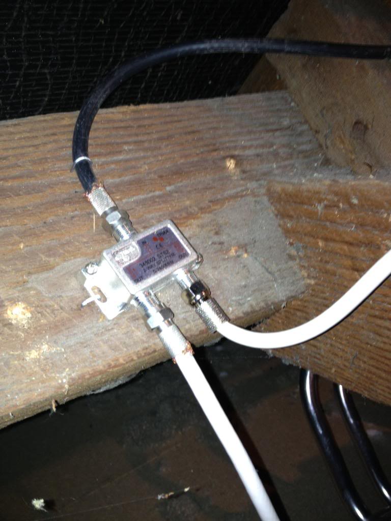
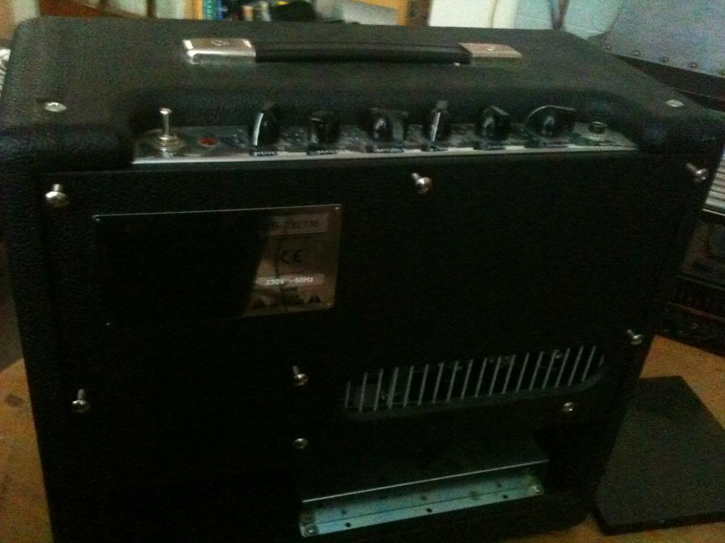
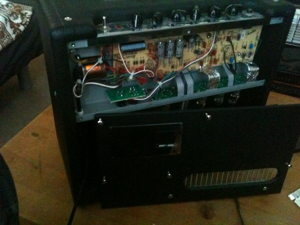
The pictures here show an antenna that has been routed through the inside of a house under the eaves into attic space, the process for splitting an antenna feed outside if the same, however you may wish to include a water proof box over the splitting equipment.

In this installation the split at the antenna is being done at the same time the antenna is being installed, but fundamentally it makes no difference. (the only difference is the colour of the cables used in the end!)

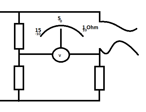
First, in order to perform this splitting task you will need to first purchase an antenna splitting device,
this is a small transformed that is used for impedance matching.
If you just split the cable into a Y shape then it would work, but the signal from the antenna would be loaded, and thus pretty weak.

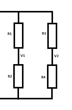
The Antenna feed has an impedance of 75Ohms, the circuit inside your TV has an impedance of 75Ohms, if you put another TV in parallel then you will halve the impedance to 37.5 Ohms.

So we use a transformer.
this transformer has one input coil with an impedance of 75 Ohms, and two output coils each with an impedance of 75 Ohms.

This will serve to effectively half the strength of the signal from the arial going to each set, so if you have a weak signal you should consider a splitter with an amplifier.

Start.
Cut the antenna wire at a point where it will be convenient to fasten the splitter box to a roof joist.
Once you have cut the antenna wire, peel back and cut off approximately 10mm of the outer insulation, and fold the screen wire of the coax cable down to cover the outer insulation sheath.

Now cut approximately 7mm of the inner insulation away from the solid signal conductor.
Screw on an F connector.
This will need to be attached to the "IN" connector on your signal splitter.

Now, you need to run cables through your roof space and down walls to the locations that you want your antenna outlets to be.
Once you have your cable in the correct place, use cable tacks to attach to joists, and C clips to secure the cable to masonry.

At the splitter end, attach more F connectors in a similar fashion to how you connected the antenna feeds F connector.

Now fix your splitter to a joist and attach the cables, the antenna feed going to the "IN" socket, and each feed to your TVs going to the "OUT" sockets.


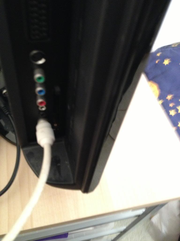
At the other end of the cable you now want to attach an antenna plug to go into the back of your TV.

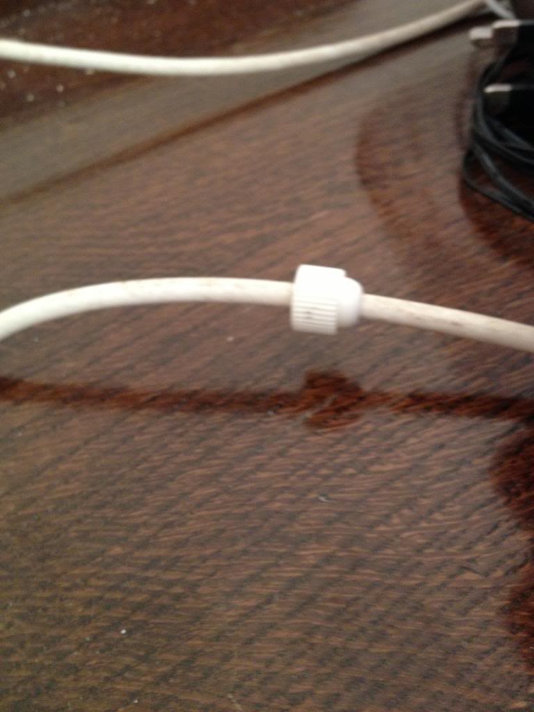
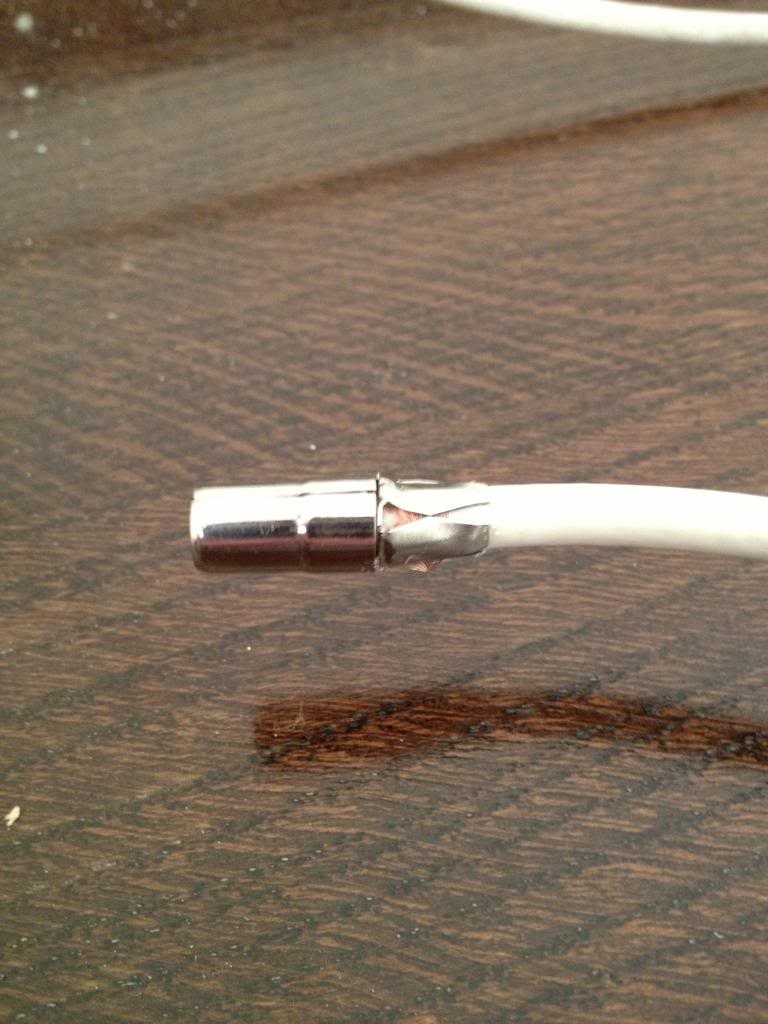
First, put the bottom screw cover for the antenna plug onto the wire.


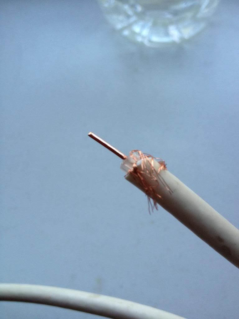
Now remove approximately 15mm of the outer sheath.
Pull the screen wire of the coax down and over the insulation, then remove the inner conductor leaving around 2mm of the insulator to stop the screen wire accidentally touching the signal wire.


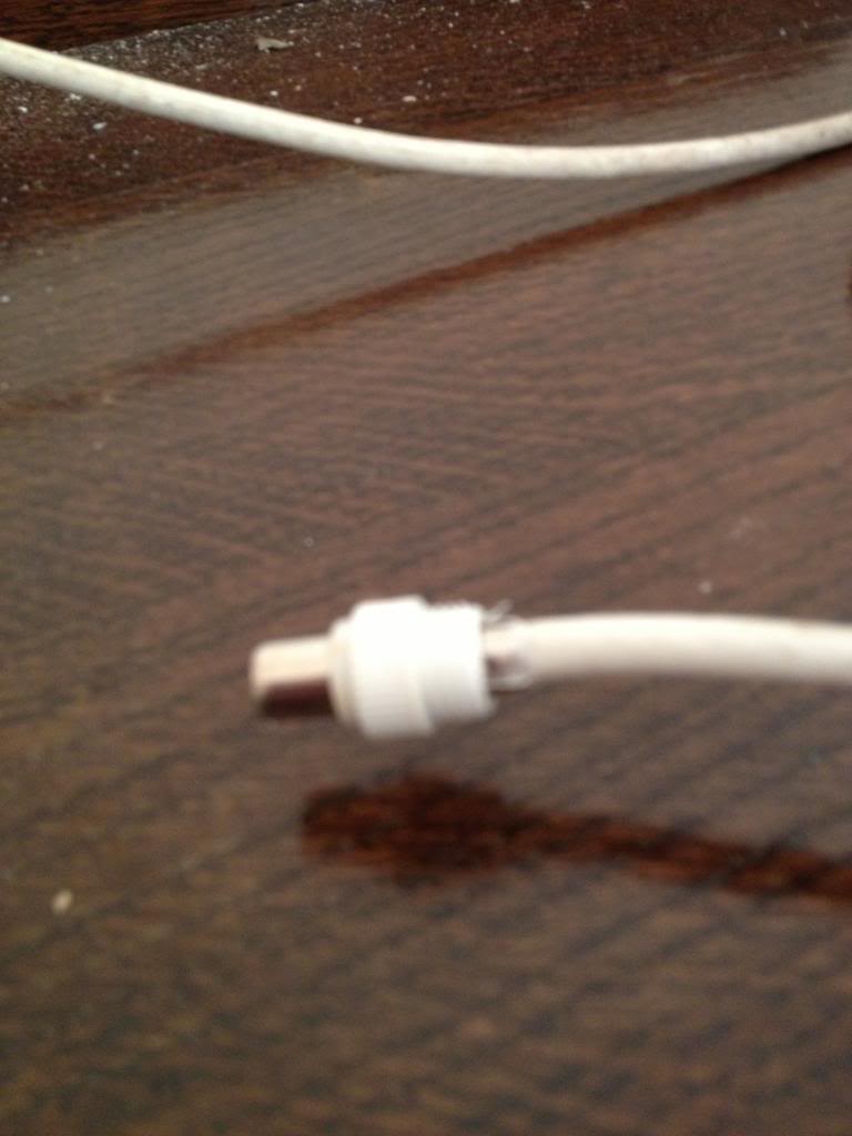
Now you need to attach the four pronged cable clip, this clip is intended to make good contact with the wire, squeeze the clips by hand to secure this to the connector and attach the tip part of the plug to the signal wire, place it over the end of the cable, (trim the signal conductor as appropriate) and secure by tightening the small screw onto the signal wire.


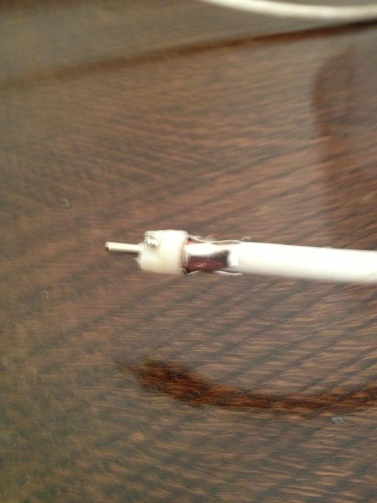
Now place the metal screen over the tip assembly.


The place the plastic plug cover over the screen and secure using the bottom screw cover that you put onto the antenna wire at the start.


Plug in a TV and ensure that you can receive a connection.


If you can't receive a connection is seems likely that either there is a break in the cable, or your screen wire is touching the signal wire at one of the connectors.

Monday, July 23, 2012

Creo Elements: Direct Modeling Express

Creo elements is a program that is built on a product that I used a long time ago called pro-engineer, it's a fast and pretty feature rich CAD program, that is used for 3D and 2D computer aided design (CAD for short) -also, it's free!

During the time that I'm waiting for my new printer to arrive I'm going to be re-familiarising myself with using CAD software ready so that I can make things on my printer when it gets here.

I can't see 3D CAD lessons being a regular thing like the electronics and code lessons, because it's just one piece of software. there is only so much that can be shared.

Calibration cube.
One of the first things that should be printed on any 3D printer is an object that you can use to calibrate the printer and settings in the software.

Having your extruder running too fast and squishing out too much plastic will lead to your layers being too fat, and plastic being squashed outwards meaning that your parts appear bigged in out edges and smaller where holes are concerned.

First, open the software, you are presented with a screen that has a blue diamond on it. that's actually a rectangle that's representing your build plane, it's got some perspective about it.

Now since you are going to be building a cube, select the rectangle tool.

Click anywhere on your build platform, and drag out a square, the small numbers that appear at the
edges tell you how big the square is.


when you get to 20 x 20 stop, and click again.

now the square turns black.
 go to the menu bar at the top and select pull


In the options box there is a field called distance, type 20 into this box and press the green tick at the top.
A grey cube now appears.


Click at the dark blue edge of the work-plane so that it is highlighted brown, now press the delete key you're left with a cube in the centre of the screen.

Now you want to turn your cube into a tube.
so click on the rectangle tool again, and the click on the top face of the cube, (anywhere on the top face)

the cube now rotates so that you're looking at the very top, zooms so that the face fills the screen, and generates a new work plane for you on the axis that you want.


move the mouse around, you'll find that as you;re moving around co-ordinates appear that tell you how far from the edge you are, or how far from the middle.

The nozzle on the solidoodle is 0.3mm wide, therefore is we create a wall thickness much more than this, the machine will try to do two passes and make a double thickness wall, but it won't be twice as thick exactly, so we will miss some vital data regarding extrusion width which will be used to help calibrate the flow settings.

click on the box 0.3mm from one corner, and drag a new square to the opposite corner.
Now select the pull tool again.This time, instead of wanting to pull the object up from teh work plane towards you, you want to pull the shape you've drawn down through the object that you've drawn.

In the distance box type -20 to create a tube, or -19 to create an open box that has a bottom face.


I'll cover how to actually use the box to calibrate a printer in a post when I've actually got the printer.

Monday, July 16, 2012

Rise of the Machines!

Well, I've finally done it.

Of course to understand why the word finally is applicable you have to understand my back story.

There is a modern day "maker" movement, a huge open source project, called RepRap.

RepRap is the foundation that takes care of the project, the project is to build (as much as is practically possible) machines that can build themselves.

it's not really a new thing as much, you've been able to cut gears to make lathes on lathes for a long time, and been able to mill flat tables for use on milling machines for a long time too.

Reprap machines are computer controlled 3d printers.

The way that they work is you feed them a length of plastic string, the machine melts the string in a hot chamber, and then pushes the melted plastic through a nozzle onto a build platform.
then the build platform, or nozzle move ever sl slightly away from each other.
and another layer is squished out of the machine, slowly but surely building up a 3d object layer by layer.

I first heard about the project in a staff news letter whilst I was working at the university of Bath in the UK, (that's where this open source project started. Fused filament 3d printing had been around a long time before that, but I had never heard of it!)
and ever since hearing about it, I've always wanted on.

but there was always been one problem. price.
It seems that there are two ways to get a 3d printer.
buy the plastic parts you need from someone who has already printed them, buy the electronics board, but stepper motors, smooth rods, threaded rods, belts sprockets, pulleys wire, power supplies, bearings bolts, etc, etc, etc...
which in total seemed to cost around £500 - £1000 to source. and about ten weeks for a first timer to build and trouble shoot. (that's after you decided which of the many many designs you wanted to make!

The second option was to buy, where buying costs £1000 and upwards.

That was until a small start up company called solidoodle came along. they are offering their Solidoodle 2 printer, a complete ready to go package.


For five hundred dollars,
yes, dollars.

the machine is a steel framed box, with an aluminium build platform measuring 150m x 150mm, the platform moves up and down by 150mm also, (this means that I can print anything up to this size (in one piece) or anything in the world, if I'm willing to glue bits together after printing.

The frame is supposed to be strong enough that you could stand on it.

A cover for the open frame, and a heated bed (rather than acrylic bed) are $100 add-ons.
when you add a roll of filament to the order and international shipping. the complete price for a working 3d printer, that should work straight from the box is $750 US dollars.

Or around £500 sterling.

I've ordered, delivery time is 8 - 10 weeks I can hardly wait.

Monday, July 09, 2012

Electronics lessons: The Resistor Simple circuits Wheatstone bridge

So, A long time ago we covered potential dividers, in that lab we used a potential divider to vary the brightness of a light bulb.

Since then we've used potential dividers to bias amplifiers and provide feedback networks for other amplifiers.

Now I'm going to introduce a very simple circuit, that really going to test that you understand, what voltage, resistance voltage difference and potential dividers are all about!

Potential difference
Now, we mostly think of potential difference as being the difference between a point and ground. when we say what's the voltage there, it's just common sense that we mean, what's the voltage there with reference to 0v, not what's the voltage there with reference to the positive power rail, or negative power rail...

When you think about it, if you have a +9, -9 and 0v power rails, If I say what's the voltage there.
you measure potential difference between 0v and that point and get +3v, if you measured between the 9v rail and that point you'd see -6v, if you measured between the -9v rail and that point you'd measure 12v.

Measuring resistance
The real crux of what we've getting into here is measuring resistance. This can be though of as a how to make your own multimeter.

We should now be comfortable with the potential divider. and what potential difference is.


So I'm going to draw a series of potential dividers, and talk about the voltages that are in use in those circuits.

First, the circuit that I'm going to talk about looks like this:
Pretty simple eh? pretty useful as well

We know that the voltage at any point is relatively easy to find

Voltage = 10v
R1 = 5
R2 = 5
R3 = 5
R4 = 5

We know that the voltage at V1 is (V / R1 + R1) x R2
in this case that's (10 / 5 + 5) x 5
10/10 = 1 multiplied by 5 is 5volts.

We know that the voltage at V2 is 5v also.

So the potential difference between V1 and V2 is zero.


Now lets change the value of R3 to 15

now V1 = 5
but V2 = 10/20 x 5 = 2.5

So the potential difference V1 - V3 is 2.5.


Now is we change the resistor R3 to be 1
V1 still = 5 (that's out reference voltage)
but V2 = 10 / 6 * 5 (10/6 = 1.66666, 1.6666 x 5 = 8.3333

The potential difference is 5 - 8.33333 = -3.3v

This sounds simple and it is.

Lets build a circuit from this.
We'll need a battery.
an analogue volt meter,
3 resistors,
2 bits of wire
1 sharpie.


Use the wire to connect resistors of a known value to the circuit, then use the sharpie to draw onto the analogue meters screen to give you calibrated marks.

Alternatively, use a light dependant resistor, and draw on the screen specific points (as measured against another calibrated device) to make a light meter.

Or use a thermistor, in a range of temperatures measured by a mercury thermometer to can have a fully calibrated electronics thermometer.


If you use load cells, (that alter resistance in accordance to the load placed on them) you have electronic scales.
Light, heat water, position of wiper on a potentiometer, if you can get a sensor to return a resistance for whatever environmental input you want, then you can use a whetstone bridge setup like the one above to measure.


Monday, July 02, 2012

Fixing an Amplifier 3

Fixing an Amplifier: 3

So that Fender Blues junior amplifier has come back under my nose, and it has a very weird problem.

Altering the volume knob makes it sound like it's tuning a long wave radio.

it whistles and hums, you can modulate the whistling sound bu altering the volume and tone.
something is definitely not right.


Trouble shooting.
So the first thing to do it try to figure out what's wrong.
Clearly there is something unstable and oscillating inside the amplifier, and this is causing random and weird noises to be picked up and generated.

So first, I take the back off.
have a cursory glance for anything loose or disconnected.
I can't find anything.

I plug the amplifier in and see if anything looks a little out of place, or weird.
the humming starts again, (notice the humming is worse because the main board is no longer completely shielded.)

Lightly touching the ribbon cables that connect the main board to the valve board produces interference, it seems that the low voltage signal going into these boards is particularly susceptible to interference.


In order to reduce this problem the ribbon that carries the instrument signal to the pre-amp valve, and the ribon cable to the valve used after the reverb recovery amplifier are shielded in aluminium foil.


The amplifier now has slightly less interference, but when adjusting the volume the weird noise (though not as pronounced) is still there.


Now I begin inspecting the circuit diagram in detail.
It seems that there is not really a lot to go wrong in these amplifiers, in fact the only thing that can go wrong is, Valves break, reverb recovery amp any break (but very unlikely without excessive abuse) and electrolytic capacitors leak.

I looked long and hard at every electrolytic capacity on the board, and found that one of the four large grey filtering capacitors was slightly deformed.

Searching on-line led me to find that what appears to have happened is, in some inane bid to save money, Fender bought the cheapest sub par quality components that they could find. there are loads of stories of these leaking, and bulging and stopping amplifiers working.

So I ordered some more capacitors and changed these for new (and better quality) ones.


the amplifier is now working perfectly again.

I have left the foil shielding on the ribbon cables, this adds a slight capacitance to the circuit and rolls off the brightness of the amplifier slightly.