So, (and not for the first time)
I reached a lull in posting, not that I was doing nothing, but I had nothing to write about.
I've been doing a few projects, but have yet to write them up.
I'm going to start writing again, but perhaps at a slower frequency.
I've tried posting once every few days, (years ago) and found that far too hard to keep up with.
I wish I'd done once a week, then I'd still have a ton of posts cued for release.
I tried once a week, but without some hardcore time spent writing and having a stack ready and scheduled for release I couldn't keep on top of writing here, making else where and a job and a family!
So now I think I'll just post as and when I need to. when I'm inspired to write a lesson, rather than looking for stuff to pad a blog, and posting when I have completed a project rather than trying to do smaller projects so that I can update more frequently.
Monday, October 14, 2013
Thursday, October 10, 2013
First accidental explosion
http://makezine.com/magazine/what-was-your-first-accidental-explosion/
So Make asks what was your first accidental explosion...
For me it's something that I won't forget. not because it was especially dangerous. but because I was so young and so paniced.
To start with it might be a good idea to set the scene.
1, I have always been interested in hacking electronics, this started from the day I took an old record player out of a skip and salvaged the components out of it using a soldering iron borrowed from my grandad.
I'd borrow books from the library to learn how to put circuits together and how to build different things.
2, As a young boy I was always interested in pirates, as in the swashbuckling kind, I used to have a book about pirates, and frequently would play "make believe pirates" I suspect (thinking about the house I was living in at the time) that I was about 7.
Hence we come to my first accidental explosion...
So one day I'm playing pirates, and I'm make believing that I'm exploring some kind of cave searching for buried treasure, in order to explore said cave I need a candle.
So I go to my "parts box" and select a light bulb, some wire and a 9v box battery. I wrap some wire around the bulb and around the "turret" terminal of the box battery, then press the other terminal of the light bulb directly onto the battery, "et voila" I have a candle, and go back to exploring my imaginary cave.
My candle however is not very reliable, I try securing parts with tape etc, but for some reason the bulb keeps going out.
Then bang, the battery explodes.
(the battery has shorted on my cello taped bits of wire (that bridge the battery connections), the current flowing has heated the insides of the battery, caused the electrolyte to expand and eventually the seal has blown.)
This is where the panic set in, the battery has exploded in my hands, (exploded is not the right term, all that's really happened is the bottom of the battery has blown out) my left hand is now covered in electrolyte, except I'm seven and have no idea what electrolyte is, I've no idea how battery's work -just that they make my toys go, in fact the only thing that I know about battery is the words battery acid. So as far as seven year old me is concerned the electrolyte from the alkaline box battery is acid, and my hand will melt any time soon.
After I realised that my hand wasn't melting I did find that the acid was just a weird murky jelly, and the inside of batteries apparently contained black sticks (carbon rods)...
So that's my first accidental explosion.
Monday, June 24, 2013
MySQL Data types and sizes
If you remember all the way back to how the coding lessons in C started, they started by looking at different datatypes, like ints long int etc, each requiring different memory spaces or being able to store different sized numbers.
The same thing is true in MySQL.
MySQL is a database server, often whenever you're making a website you have a few diffeerent things to think about.
Lets imagine you;re making an on line magazine, or a piece of forum software, you;re going to have authors, (that's a relatively short bit of text, -who's name is over 20 letters?)
but then you also have article text, or posts etc that's going to be a fairly hefty chunk of text.
So lets look at the kind of thing you'll use to have article titles, or by lines, that's likely to be a varchar type.
Varchar is like a string, you specify how much text you want to be able to store in the field. so for a name you may decide that 20 characters is enough, and you;d specify varchar(20).
for storing text there are a few different types of data field.
Notably these don't hold a number of characters, they actually hold an amount of data which is measured in bytes.
(this is important as you might be using a double byte character set -then you can only store half as much text by character count.
So, the data types are
Tinytext which can store 256 bytes,
Text which can store 65,535 bytes (64Kb)
Mediumtext -which can store 16,777,215 bytes (16MB)
Longtext 4,294,967,295 bytes that's a huge 4GB!!!
so how does this work? a 4GB chunk of text is huge to just be a row on a table.
well, the MyISAM tables actually have a maximum size of 65,535 bytes (that means a row can only be that size.) -but surely if a text field can be that by itself.
What happens is that a pointer is stored with the row data that points to the large text chunk, that file pointer is anywhere between 1 - 4 bytes. That way large data is store outside of the normal row.
Monday, June 17, 2013
A Simple Guide To Complying With The EU Cookie and Privacy Law
I started my blog as a guide for putting things together, over time that's slipped through hardware, software, coding, computer aided design, building speakers etc, and has now slipped into web development a little bit.
I can't imaging that this web design kick will last a terribly long time. but whilst it's in my mind and giving me inspirstion to write posts then I'll run with it!!
In the UK (and the EU) we now have a cookie law.
this is a bit weird, and smacks of politicuians thinking that we're eating too many cookies, and that makes you fat, and there is an obecity epidenic, also, when you eat lots you crap lots too, and the sewers can only take so much before the pipes come clogged and then there is too much for the interpipes, and it's falling appart, and it's all the fault of the cookie, or something like that.
In principal I agree that there are some good, bad and ugly uses of cookies.
But like all half baked laws (I promise I'll stop with the cookies are like actual biscuit jokes soon) this one is pretty easy to make a mockery of.
But I've decided that on the site that I've made I'll play within the spirit of the law, as well as the letter of the law, and here's how I've done it.
First, I took a look round, it seems that just letting people know that you use cookies is enough.
So the easiest way to be compliant with the law is to just put a small banner on your site that simply says, "this site uses Cookies" some people go further by saying by continuing to use this site you agree that we can store cookies on your computer, but really you don't need to do that.
The message I put up also links to privacy policy where you get the additional information that the cookies are only used because of the shopping basket feature, that the cookie is cleared if the basket is emptied etc...
Basically, the key to keeping in line with this law is let your users know you keep cookies, and go the extra little way to explain to your users why it is that you need to store anything on their machine.
Monday, June 10, 2013
Development, Testing Staging and finally going live
About development.
So in the last blog post I mentioned that I was doing a little site development work.
Just for a moment, forget about software methodologies water flow and scrum, agile etc.
lets look at the very very most basic functions.
as far as I am aware, there is no new method for test, yes you can test on focus groups, yes you can test with customers, or you can test on your own.
in any situation there will be four main groups, (and this is true even if you're a one man show doing stuff in your spare time like myself) equally it was true when I worked in a software house, and equally it's true now for the developers where I work.
but you'll be amazed by the amount of people that don't get this and don't understand this, they think that it's fine to round a corner here or there, that things could get done easier if only...
You need to set up different environments for each.
Those environments are as such:
Development, - this is the environment that you develop in, it's usual for this to be entirely self contained on your own computer, you edit something and straight away you can see the results -or in deep can see a lack of results because it doesn't work.
It's usual for debug modes to be set, and error reports to appear on screen along side page content for websites. so that you can see and fix errors straight away.
Test, -This environment is for testing, formal testing, you're not displaying errors now or debugging, you;re testing to make sure that it works, your test environment should be as close to what will be deployed as you can make it.
an example of this is the work that I've been doing, I've developed on a windows machine, and have been a bit lazy when it comes to capitalisation, I'm going to deploy the site on Linux hosting, and on Linux capitalisation matters! my test environment therefore is my Raspberry Pi, it's just a small Linux machine.
Staging, -Staging is for your customer testing and load testing, this needs to be EXACTLY like your live environment, same software, same versions of software, and as near as possible same machine specifications, when you do load testing if you have a powerful machine you'll think that the site can handle a lot more traffic than that old server that your live site is on.
If you stage on Windows, and go live on Linux you won't notice that little error that means a dead link, (capitalisation matters on Linux systems!)
Different configuration files for databases can allow you to be lazy as to whether column names or database names are capital or lower case letters.
then finally live, -the environment that the world will see, or at least everyone who will see the site.
You can use the same hardware for test and live, (assuming that you've bought hosting from somewhere then you may want to run www.mysite.com and test.mysite.com -that's fine! but be aware that when you're load testing your test site you'll be loading your live server too!
Monday, June 03, 2013
LAM(Pi)
So over the weekend I decided to use my Raspberry pi to do a little bit of website development.
This is an interesting task. I've been actually developing the site on a windows box, but as I plan to host on inux evenutally I thought that I should test on linux, usually this would mean spinning up a VM, but I thought since I have the Raspberry Pi, (and I want to think of a web enabled hardware project also, now would be a good time to get to installing some standard LAMP type tools
first install apache
apt-get apache2
then php
apt-get php5
then mysql
apt-get mysql-server
then the PHP and my sql tools
apt-get php5-mysql
then I want to have a live AND a test site, to you need to configure apache.
I'm putting my test site on an alternate port (I suppose I could use named hosts)
do as well as making a new site in site-available and linking it to sites enabled you have to edit ports.conf too
now, a load of people suggest installing phpmyadmin.
This is a pretty cool tool, I've used it plenty of times before when developing siets. but, I don't reall want that on this box, the reason is, that when I used it before there were pretty much no graphical tools for mysql administration, it was CLI or developing some kind of app.
since Oracle bought MySQL the've written some pretty nice GUI connect and administer tools. (which is weird because the oracle ones are pretty bloated and shite)
then I want to use the GUI tools on my windows machine to admin the mysel server
So I keep getting a connecttion failed error
can't connect to server 10060
Turn out that this means taht the server isn't listening,
but it should be, I am actually running code on it, my site is working perfect databases are being accessed.
Oh wait, turns out that the default config is to listen for connecttions to local host only.
So edit /etc/mysql/my.cnf and change the bind address from bind 127.0.0.1 to bind (your ip address) (make sure you set a static address, you don;t want this changing!!)
But wait, now the tools are saying they can see the server, but throw up the message
Host 192.168.1.11 (my computer) is not allowed to connect to this MySQL server.
You have to grant the user access from specific IP locations. (a pretty neat sucurity feature I guess)
To do this you'll need to log on to your MySQL installation as root.
(so from the command line (Via SSH if you like))
mysql -u root -p
Then you'll want to use the MySQL equivalent of the system databases,
use mysql
And finally, grant access to the machine to be able to connect to the server:
grant all on *.* to root@'[clinet IP]' identified by 'password'
(or grant select insert delete on *.* to web_site_user@'web_site_server_IP' identified by 'web_site_user password')
Monday, May 27, 2013
Making an extension lead, (plug end)
I made a post last week about adding an extension lead socket to a length of wire.
Now I'm going to detail the plug end.
So start by looking at the pins, here you'll find two screw holes that secure the male plug pin part to the back cover that you hold whilst plugging or unplugging.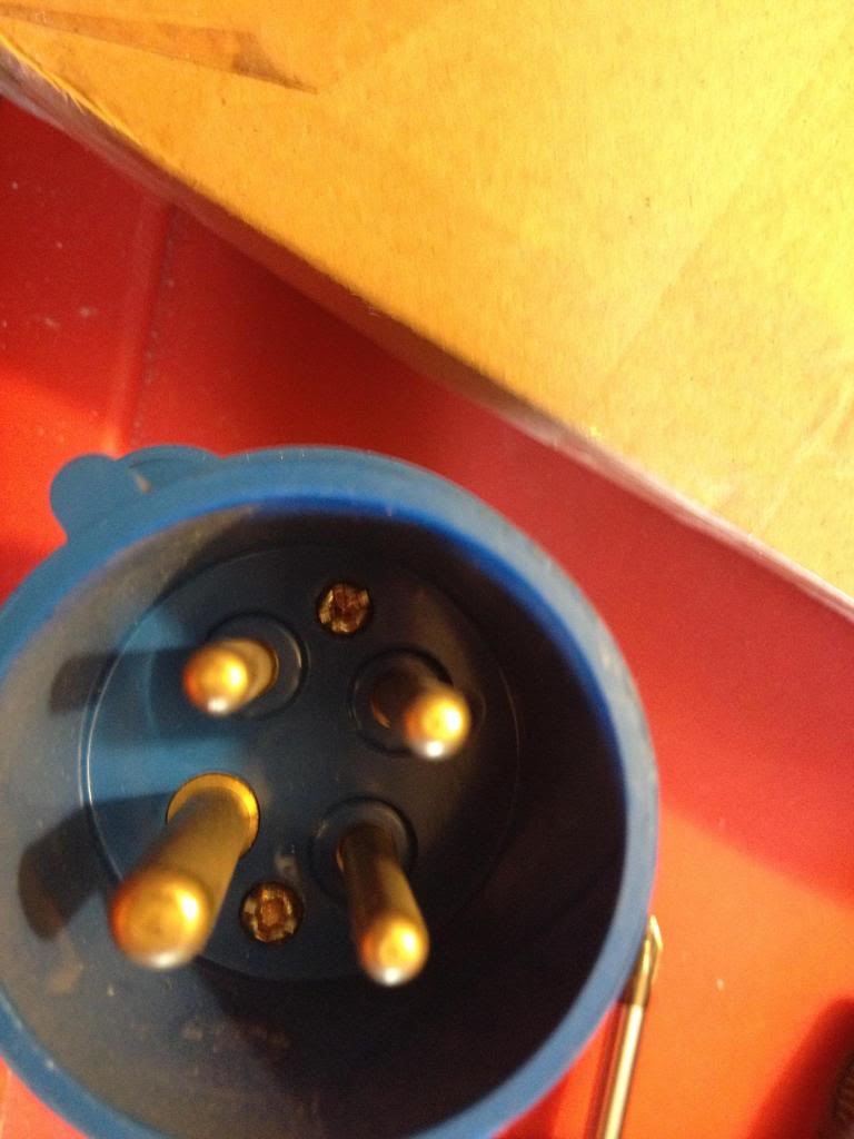
undo these screws and remove the back cover, then put the back cover onto the wire that you're using to make the extension lead, (or the flex for the equipment that you're attaching the plug to) so that you;ll be able to close the plug later once the wires are connectted.
Again, start by stripping your wire.
then cutting the phase wires slightly shorter than your earth wire, (so that if the cable is strained, your equipment would go dead before it became unearthed)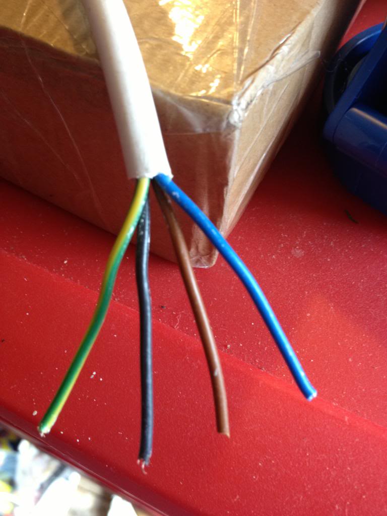
Now loosen the cable clamp and attach the wires to the plug terminals.
Finally clamp the cable in the cable clamp, push the back cover on, and screw it back into place with the screws that are next to the plugs inside the plug shroud.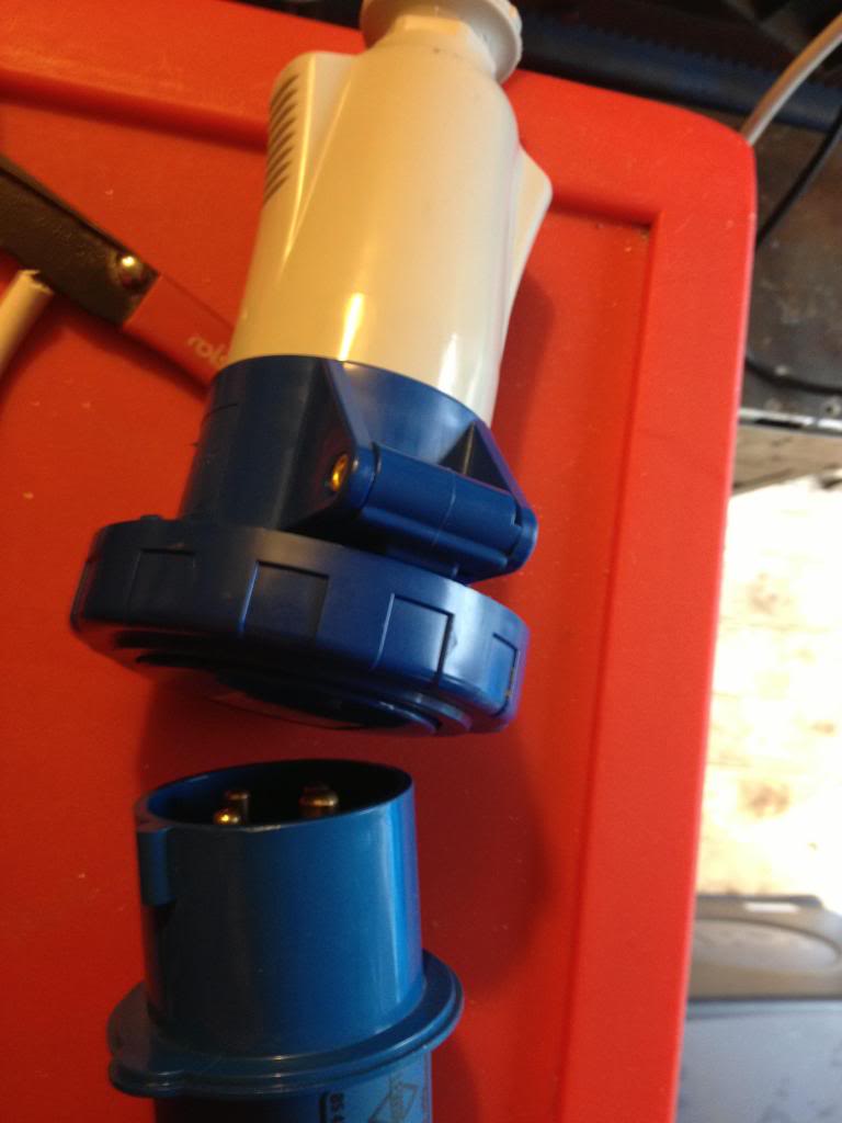
Your extension lead is now complete.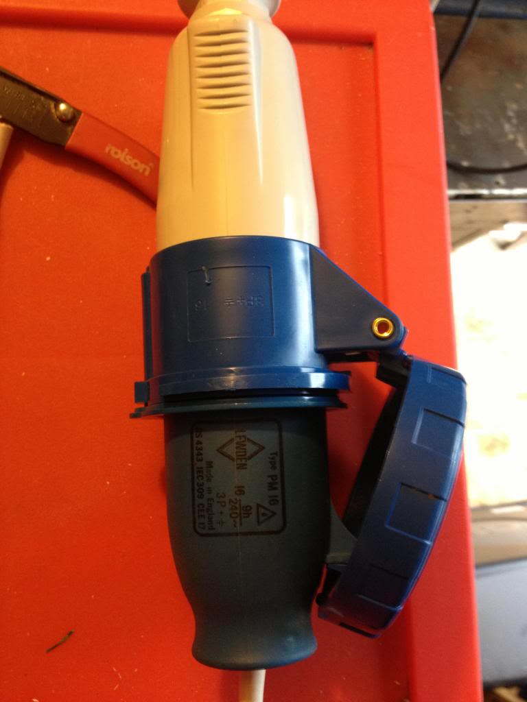
Monday, May 20, 2013
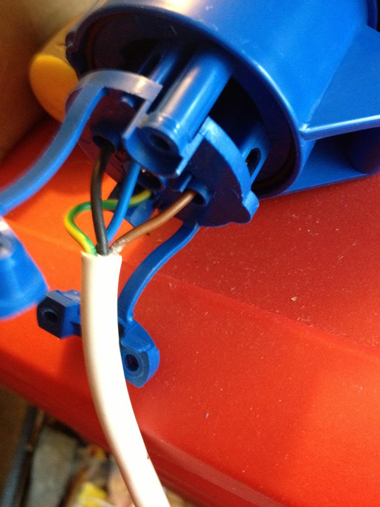
Making an extension lead, (socket end)
So I dealt with mains electricity a couple of weeks ago.
Now this is a quick post on how to put together an extension lead.
At the end of the post on mains power I was pretty keen to stress that there were colour codes associated with mains power, well, as it happens the cable that I was able to buy for my 3phase extension lead does not conform to that colour scheme.
The cable has conductors that are Brown Blue and black with a green and yellow earth conductor.
So to start,
The cable I'm making will be a 16amp three phase 240 Volt cable.
That means a 4 pin blue "commando" socket is needed. There are fairly uncommon in the UK (as our 3phase tends to have 415 volts. quite uncommon in the US (where the three phases are 120volts) but apparently is quite common in Sweeden. so you can get the plugs you want.
I found these plugs (and sockets) by searching Ebay for IP44, and IEC 60309.
You can find these at screw fix, (where they are £11 for each plug -I paid £1 each for five on eBay) sockets are also available at screw fix, but again I found them cheaper on line.
(screw fix is a nationwide UK distributor of all sorts of trade type building materials, it's open to the public, so if you can't wait for an item to ship they may be the best bet!
So I'm going to start with he socket end.
Take the socket apart such that the back cover is away from the connectors,slide the back cover over the wire (with the open side facing the bare end) so that you'll be ready to seal up your connector later!
To remove the back of the socket use the two cross head screws that are located inside the grip portions.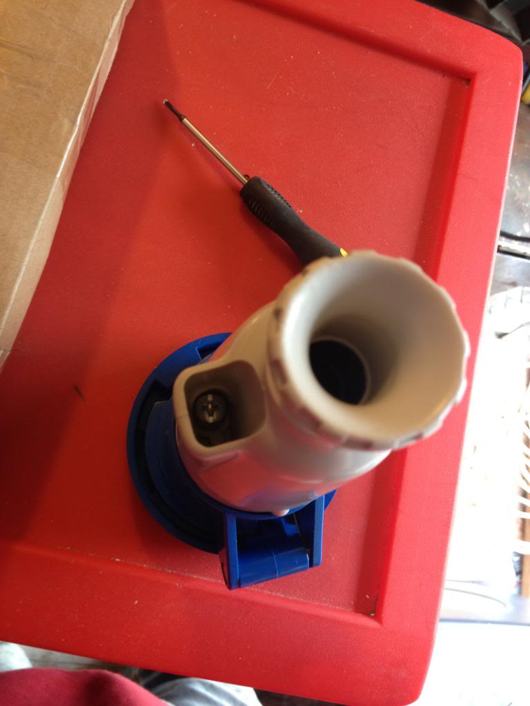
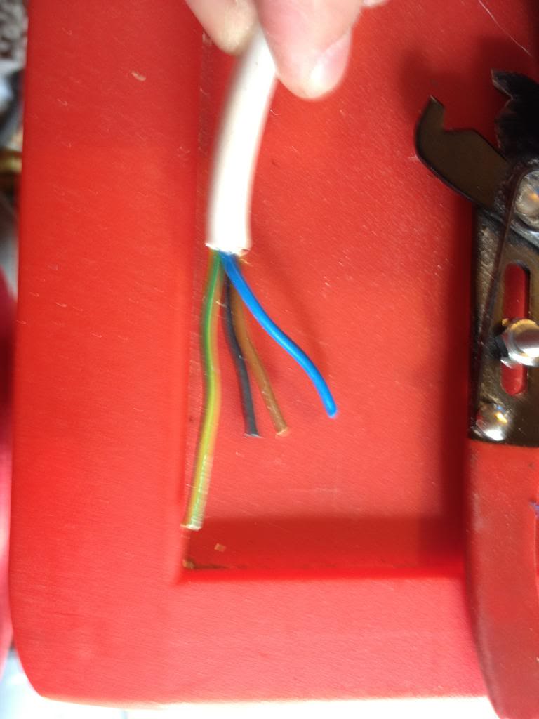
Now take your 4 core wire and removing some of the outer insulation.
Then cut the phase leads to be shorter than the earth lead -the reason for doing this is that if the cable were ever put under strain and connections were to come out of the plug then the equipment you;re using would stay earthed, the worst scenario for electricity would be using a piece of equipment that was unearthed, that malfunctioned and became live, then you're the path to earth! By leaving the earth lead with some slack in to you're able to know that safety can be maintained, even if the cable has been put under such strain that conductors have started being pulled from connecting plug pins!
Now slide the back of the lead into place.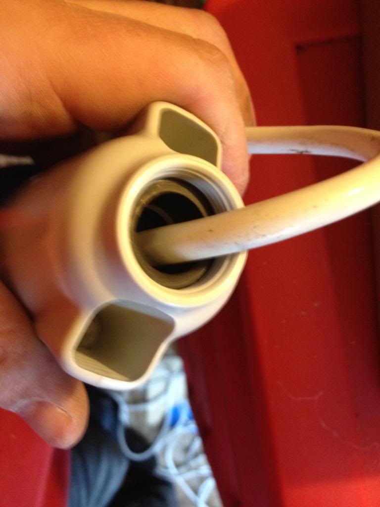
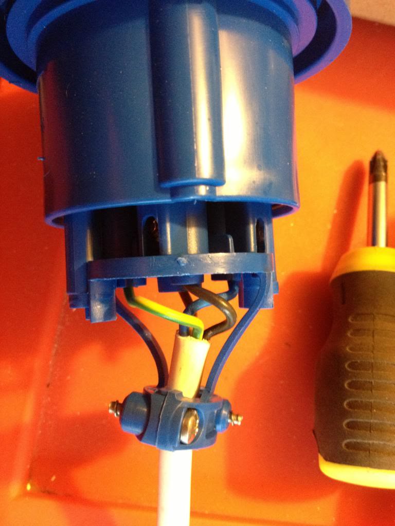
you can see a large black rubber washer, (it's about a half inch thick).
This is what seals the unit from weather (that and the little black o-ring on the other end)
Once you've gotten the back in place and screwed down, slide the final part of the back into place.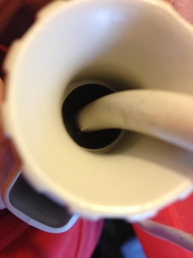
this screws down squashing the rubber washer forcing it to grip the cable and provide a waterproof seal.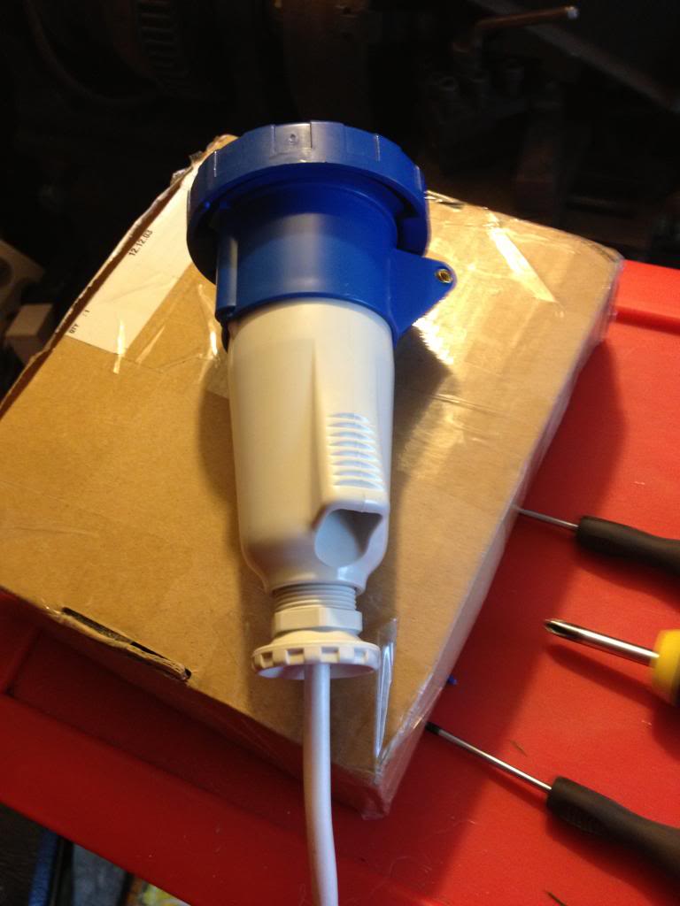
Finally, you have a lead with a socket on the end.
Now this is a quick post on how to put together an extension lead.
At the end of the post on mains power I was pretty keen to stress that there were colour codes associated with mains power, well, as it happens the cable that I was able to buy for my 3phase extension lead does not conform to that colour scheme.
The cable has conductors that are Brown Blue and black with a green and yellow earth conductor.
So to start,
The cable I'm making will be a 16amp three phase 240 Volt cable.
That means a 4 pin blue "commando" socket is needed. There are fairly uncommon in the UK (as our 3phase tends to have 415 volts. quite uncommon in the US (where the three phases are 120volts) but apparently is quite common in Sweeden. so you can get the plugs you want.
I found these plugs (and sockets) by searching Ebay for IP44, and IEC 60309.
You can find these at screw fix, (where they are £11 for each plug -I paid £1 each for five on eBay) sockets are also available at screw fix, but again I found them cheaper on line.
(screw fix is a nationwide UK distributor of all sorts of trade type building materials, it's open to the public, so if you can't wait for an item to ship they may be the best bet!
So I'm going to start with he socket end.
Take the socket apart such that the back cover is away from the connectors,slide the back cover over the wire (with the open side facing the bare end) so that you'll be ready to seal up your connector later!
To remove the back of the socket use the two cross head screws that are located inside the grip portions.
Then cut the phase leads to be shorter than the earth lead -the reason for doing this is that if the cable were ever put under strain and connections were to come out of the plug then the equipment you;re using would stay earthed, the worst scenario for electricity would be using a piece of equipment that was unearthed, that malfunctioned and became live, then you're the path to earth! By leaving the earth lead with some slack in to you're able to know that safety can be maintained, even if the cable has been put under such strain that conductors have started being pulled from connecting plug pins!
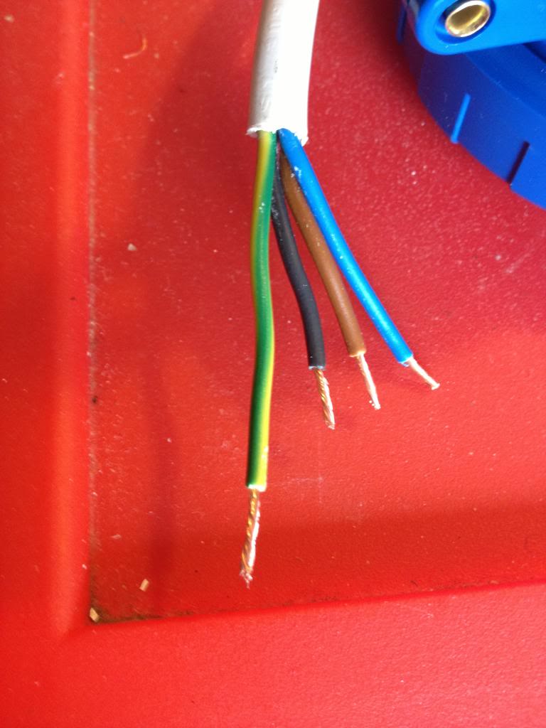
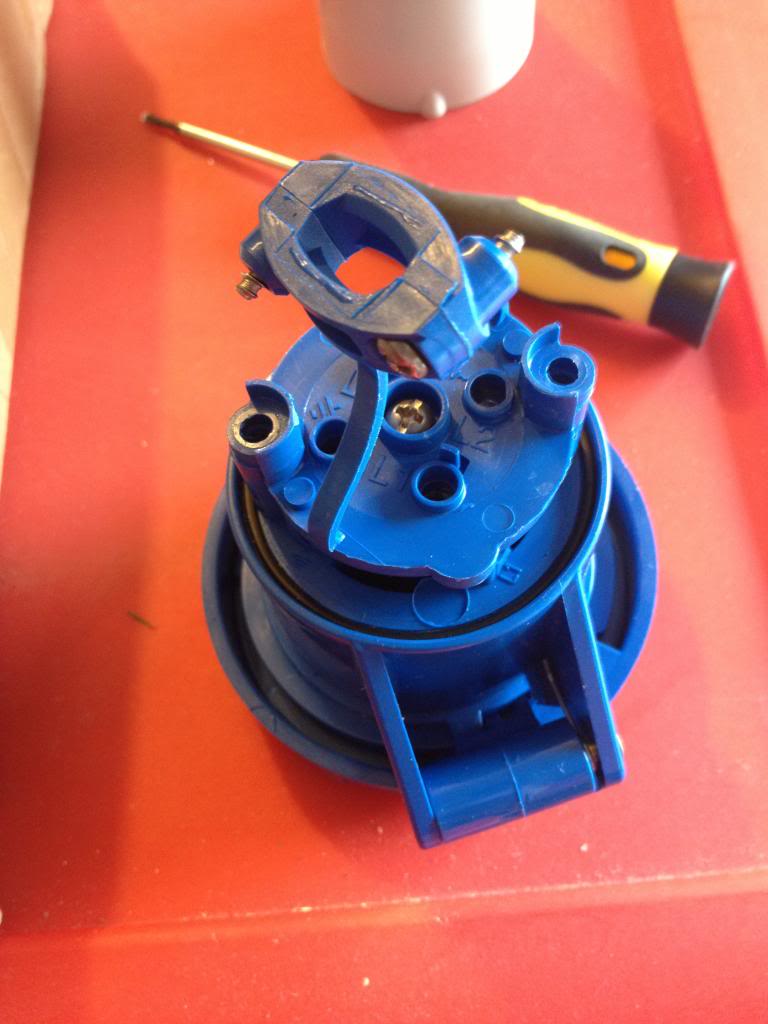
Now open up the cable clamp on the blue half of the connector and attach the wires into the holes indicated, with the brown black and blue wires being the phase wires and the green and yellow being the earth wires.
Then close up the cable clamp.
Now slide the back of the lead into place.
This is what seals the unit from weather (that and the little black o-ring on the other end)
Once you've gotten the back in place and screwed down, slide the final part of the back into place.
Monday, May 13, 2013
Mass production, tooling, strategies and budgeting.
This blog could be titled, How to get it wrong.
I'll start with the story, then I'll point out the failings.
A few weeks ago I made a new heater for my solidoodle 3d printer, I was quite happy with the results, despite having broken a drill bit in my heater block, I got around that, and I decided that was my fault, I clearly wasn't drilling the hole straight, it was a small drill bit, and they often break anyway...
When I bought the aluminium bar to make the hot end I had decided that I would probably want to make something else anyway, so I got a 2 meter length.
After making that first hot end I decided that I was going to make and sell a whole load.
I had enough aluminium bar, I had bought a hundred heaters at the start of the project, (knowing that I could sell the heater elements on their own!)
So I started cutting up that long bar of aluminium into 100 small pieces.
by about the 3rd piece I gave up and went to ebay and bought a small hobby band saw. -this worked great for cutting the aluminium, right up until the blade broke -though this had come with the saw, (which only cost £30), and had made 99 cuts, -failing on the last)
After this I got my set square and scribe and marked out where I needed to drill holes on all 100 blocks that I had cut. then I centre punched them. -this is time consuming, that was 600 holes that I marked!
After this was done I decided that I'd start drilling, rather than drilling by hand I decided that I'd use my fathers pillar drill, a Draper tool, I dutifully loaded the drill bit into the chuck, and set about drilling holes, I started by drilling 2.5mm hole through all of the holes I'd marked, a lot of the holes needed to be 2.5mm, others would benefit from a pilot hole being drilled anyway.
However I found that on the point where the hole for holing the thermistor met the hole for the screw securing the thermistor, the drill bit would catch and break. this was the same problem I'd had with the hand drill, but now I was getting this with a machine drill, one that was square, level and had no lateral forces, clearly there was a problem with the way that the cut was being made, swarf from the hole was catching and causing the bits to break at an alarming rate.
Eventually I managed to get a few holes drilled carefully that did meet, (afterwards I bought some 2.5mm end mills that I would use in the drill to make these holes meet more successfully!
At the end of the time I had set aside that day I had 11 pieces half made, I had the holes for the thermistor set-up drilled successfully, and the long hole through the block pilot drilled. at this point I'd been at it around two hours, and decided that was enough... -and besides the drill had gotten quite warm and I thought it could use a rest!
One morning the following week I decided that I'd continue my project. however within ten minutes of starting the drill the motor had caught fire.
In the end I took the pieces home and finished the first batch with a hand drill.
I tapped them and installed the heater elements.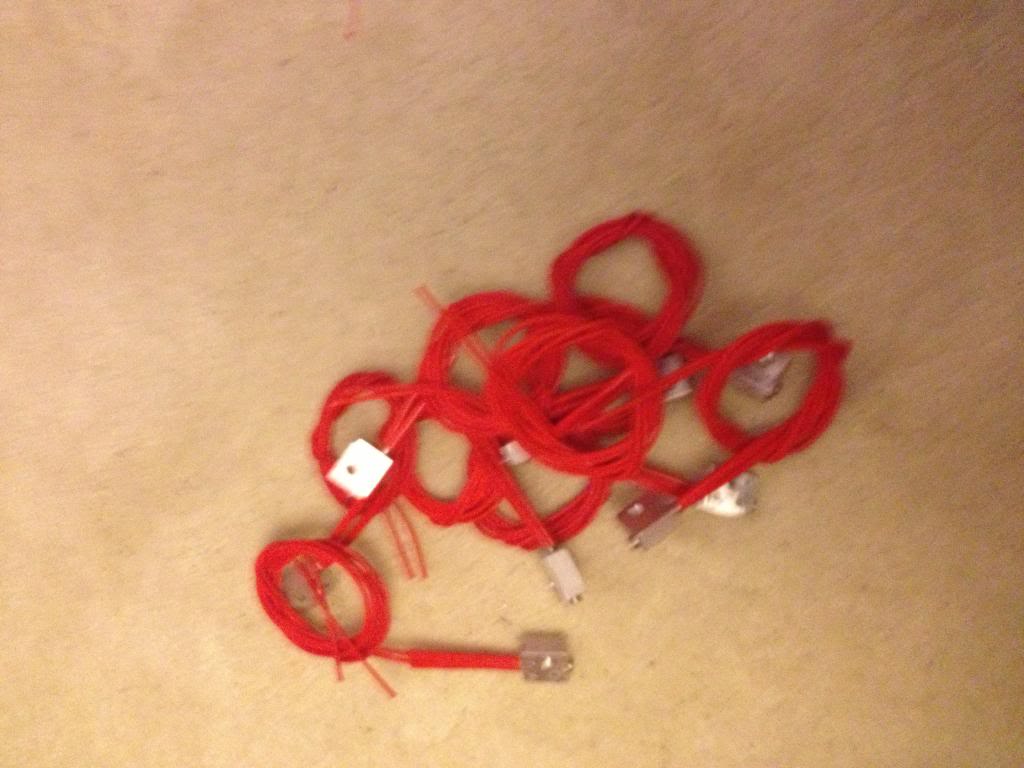
As it's a new month I've been paid and gotten some more money to spend on this project I've now ordered the thermistors, wire and heat shrink to finish these heaters up.
So... let's look at where I went wrong.
First, I'm hoping to sell these for around £12 - £14, this is in line with what others have sold for on Ebay.
the heaters were £130 + £15 import VAT for 100
Aluminium bar was £10
Thermistors are£70 for 100
heat shrink is £5 for the 6m of 1mm heat shrink I need
and £3 for the 5m of 3mm heat shrink I need.
wire is around £2 for 10 meters, (and I need 200meters) so £40
the grub screws cost around £15
So a quick sum up looks like I'm nearly £250 in the hole with materials.
Postage on each item is expected to be around £1. (so that's another £100)
Ebay will take ~£2 per item, (£200)
and pay pal will also want their 10% (£1.40 per item, times 100 = £140)
so that'll be around £700 of costs.
I'm hoping to sell these for a total of £1400
but here's where the problem starts....
now take roughly 25% of that away in taxation and national insurance that I'll need to declare. that's £175, leaving £525
Trying to do this cheaply has meant that I broke around £5 of drill bits whilst trying to make the blocks, and that £10 saw blade for the band saw.
(leaving £510)
I'd busted my dads pillar drill, because it's a hobby tool, not an industrial tool, it's meant to spend about 30 seconds being on, then have ten minutes to cool down, now spend nearly three hours in constant use, so that it over heats, and breaks down the insulation, (and then catches fire)
a complete replacement is around £300, second hand maybe £150, or a new motor will be around £100
My "profit" is now a pretty shabby £400...
then I spend a couple of hours cutting up the aluminium bar, a few more hours in front of the drill, a couple of hours sourcing materials, I'll conservatively spend probably 15 minutes per item with listing on ebay, talking to buyers, packaging and going to the post office to actually post the things.
(that's 1500 minutes, or about 30 more hours). I spend around an hour designing the thing in the first place.
Based on the initial ten I have that's 6 hours of machining and making,
So that 100 will be about 60 hours of machining, plus 30 hours of listing and posting.
So that £400 I've got remaining will need to pay for about 100 hours work. about 2/3rds minimum wage.
in other words.
I started out thinking, cool, the parts for this will make me loads of money, I'll spend about £2.50 on an item that I can sell for £14.
But,
using hobby tools has increased costs due to breakages.
Using hobby tools has meant that I can't work for more than an hour at a time without significant machine downtime to cool off, increasing the amount of time take to produce parts.
Funding this venture myself has meant that I've had to wait until pay day to get more funding. - I could have taken this to a kikstart project, but them I'd have 100 angry customers breathing down my neck saying that my lack of planning or prep wasn't their fault, and where is their money etc.
The long and the short of it is:
before you decide that you want to give up your day job and live the dream of running a tech startup. do your sums first. be realistic.
I was wishfully thinking that I might get around £700 for what would be an easy day stood at a band saw and a drill. -actually I was thinking I could use an ordinary hack saw to do this work!
What I though would be around £100 per hour I'll retired a millionaire next week, has actually resulted in being a drain on time and resources. Maybe with a few thousand pounds of investment for industrial tooling I'd do better -but I doubt that also!
I'll start with the story, then I'll point out the failings.
A few weeks ago I made a new heater for my solidoodle 3d printer, I was quite happy with the results, despite having broken a drill bit in my heater block, I got around that, and I decided that was my fault, I clearly wasn't drilling the hole straight, it was a small drill bit, and they often break anyway...
When I bought the aluminium bar to make the hot end I had decided that I would probably want to make something else anyway, so I got a 2 meter length.
After making that first hot end I decided that I was going to make and sell a whole load.
I had enough aluminium bar, I had bought a hundred heaters at the start of the project, (knowing that I could sell the heater elements on their own!)
So I started cutting up that long bar of aluminium into 100 small pieces.
by about the 3rd piece I gave up and went to ebay and bought a small hobby band saw. -this worked great for cutting the aluminium, right up until the blade broke -though this had come with the saw, (which only cost £30), and had made 99 cuts, -failing on the last)
After this I got my set square and scribe and marked out where I needed to drill holes on all 100 blocks that I had cut. then I centre punched them. -this is time consuming, that was 600 holes that I marked!
After this was done I decided that I'd start drilling, rather than drilling by hand I decided that I'd use my fathers pillar drill, a Draper tool, I dutifully loaded the drill bit into the chuck, and set about drilling holes, I started by drilling 2.5mm hole through all of the holes I'd marked, a lot of the holes needed to be 2.5mm, others would benefit from a pilot hole being drilled anyway.
However I found that on the point where the hole for holing the thermistor met the hole for the screw securing the thermistor, the drill bit would catch and break. this was the same problem I'd had with the hand drill, but now I was getting this with a machine drill, one that was square, level and had no lateral forces, clearly there was a problem with the way that the cut was being made, swarf from the hole was catching and causing the bits to break at an alarming rate.
Eventually I managed to get a few holes drilled carefully that did meet, (afterwards I bought some 2.5mm end mills that I would use in the drill to make these holes meet more successfully!
At the end of the time I had set aside that day I had 11 pieces half made, I had the holes for the thermistor set-up drilled successfully, and the long hole through the block pilot drilled. at this point I'd been at it around two hours, and decided that was enough... -and besides the drill had gotten quite warm and I thought it could use a rest!
One morning the following week I decided that I'd continue my project. however within ten minutes of starting the drill the motor had caught fire.
In the end I took the pieces home and finished the first batch with a hand drill.
I tapped them and installed the heater elements.
So... let's look at where I went wrong.
First, I'm hoping to sell these for around £12 - £14, this is in line with what others have sold for on Ebay.
the heaters were £130 + £15 import VAT for 100
Aluminium bar was £10
Thermistors are£70 for 100
heat shrink is £5 for the 6m of 1mm heat shrink I need
and £3 for the 5m of 3mm heat shrink I need.
wire is around £2 for 10 meters, (and I need 200meters) so £40
the grub screws cost around £15
So a quick sum up looks like I'm nearly £250 in the hole with materials.
Postage on each item is expected to be around £1. (so that's another £100)
Ebay will take ~£2 per item, (£200)
and pay pal will also want their 10% (£1.40 per item, times 100 = £140)
so that'll be around £700 of costs.
I'm hoping to sell these for a total of £1400
but here's where the problem starts....
now take roughly 25% of that away in taxation and national insurance that I'll need to declare. that's £175, leaving £525
Trying to do this cheaply has meant that I broke around £5 of drill bits whilst trying to make the blocks, and that £10 saw blade for the band saw.
(leaving £510)
I'd busted my dads pillar drill, because it's a hobby tool, not an industrial tool, it's meant to spend about 30 seconds being on, then have ten minutes to cool down, now spend nearly three hours in constant use, so that it over heats, and breaks down the insulation, (and then catches fire)
a complete replacement is around £300, second hand maybe £150, or a new motor will be around £100
My "profit" is now a pretty shabby £400...
then I spend a couple of hours cutting up the aluminium bar, a few more hours in front of the drill, a couple of hours sourcing materials, I'll conservatively spend probably 15 minutes per item with listing on ebay, talking to buyers, packaging and going to the post office to actually post the things.
(that's 1500 minutes, or about 30 more hours). I spend around an hour designing the thing in the first place.
Based on the initial ten I have that's 6 hours of machining and making,
So that 100 will be about 60 hours of machining, plus 30 hours of listing and posting.
So that £400 I've got remaining will need to pay for about 100 hours work. about 2/3rds minimum wage.
in other words.
I started out thinking, cool, the parts for this will make me loads of money, I'll spend about £2.50 on an item that I can sell for £14.
But,
using hobby tools has increased costs due to breakages.
Using hobby tools has meant that I can't work for more than an hour at a time without significant machine downtime to cool off, increasing the amount of time take to produce parts.
Funding this venture myself has meant that I've had to wait until pay day to get more funding. - I could have taken this to a kikstart project, but them I'd have 100 angry customers breathing down my neck saying that my lack of planning or prep wasn't their fault, and where is their money etc.
The long and the short of it is:
before you decide that you want to give up your day job and live the dream of running a tech startup. do your sums first. be realistic.
I was wishfully thinking that I might get around £700 for what would be an easy day stood at a band saw and a drill. -actually I was thinking I could use an ordinary hack saw to do this work!
What I though would be around £100 per hour I'll retired a millionaire next week, has actually resulted in being a drain on time and resources. Maybe with a few thousand pounds of investment for industrial tooling I'd do better -but I doubt that also!
Monday, May 06, 2013
Electronics lessons: Mains Power -single phase and three phase
Whilst writing this blog I've stayed away from things that I would consider dangerous.
That is to say I've completed some projects that I've felt were either too big to document, (like when I put up my new storage shed in the garden and put electrics and lights etc in.) -at the time my thoughts were like this. it's OK to tell someone to stick bits of wood together to make a speaker, it's OK to say to people use this step down transformer and deal with the safe voltage that comes out the other side. I even thought it fine to tell people to stick electrodes into water to generate hydrogen/oxygen gases!
But big scary voltages have been something that I've stayed away from, the thing about mains utilities is that, you can smell gas, and know to shut off the supply and get out. you can see water and hopefully have the intelligence to get out before drowning. Electricity is completely invisible, it's not a substance, it's a force.
Anyway, that might give you an insight as to how I feel about mains electricity. it's dangerous to the point of deadly, and too much confidence can lead to mistakes that ultimately can kill you.
As a point of reference I live in the UK, this means that for me, voltages come in 120v for site tools, (where the 120v is considered safer due to lower voltages) this voltage is obtained by using those little yellow transformer boxes.
240v comes into every homes, (at least every connected home, I suppose off grid homes might make their own standards).
440V is considered industrial and is what most three phase power outlets are going to be using.
Voltages are measures with respect to neutral, live - neutral.

Single phase is what I've mostly dealt with, it's easy to visualise, easy to look at and easy to understand. remember that the positive is measured with respect to neutral, not with respect to ground.
Sometimes a single phase supply is actually a 2 phase supply, where instead of a virtual earth, or earthed neutral, there are two hot phases where the phases are 180 degrees apart.
the sum of the phases is zero, (e.g at 0 degrees phase 1 is 0v, phase two is at 180 degrees and is also 0v, at 90degrees, phase 1 is +120v and phase two is 270 degrees and -120, (+120 + -120 = 0v), the total potential difference between the two phases is 240 volts, (120 - -120 = 240)
Here's where it starts to get a little more complicated.
Now there are three phases, each phase is 120 degrees behind the next, they are still sine waves, and they are still measured with respect to neutral, but there is no neutral in the transmission line, -when power enters your premises in a single phase set-up there is a live and neutral line. when you get three phase there is only 3 live wires, no neutral. (you can make a neutral by connecting all the phases together, because the sum of the phases is zero) -but I'll cover that in a later lesson.
You can see at 90 degrees now phase 1 (blue) is at at the top of it's rising cycle 240v, and phase 2 (green) is just coming up from the bottom (so during it's rising cycle) and is -120v, whilst phase 3 (red) is getting towards the bottom of it's falling part of the cycle, and is -120V
240 + -120 + -120 = 0
it's just a bit of copper, fundamentally there is nothing to stop me from doing that, provided I wire the other end the same way, where's the problem?
The problem is what happens when I'm out, and whatever appliance I've wired badly breaks, what if my wife/girlfriend/boyfriend/husband/friend/son/daughter/mother/father/grandparent etc decides that they just want to check the fuse on the plug, then they see the wires connected wrongly, so think that might be the problem. or something see's an earth wire, and decides that they can splice that wire to earth something else, -except it's not earth, it's live, and they are probably now dead.
Colour codes are set by the IEE.
for single phase systems.
Brown = Live, (the old colour was red)
Blue = Neutral, (the old colour was black)
Green and yellow stripe = Earth, (the old colour might be plain green)
for three phase systems,
Brown = Phase 1 (old colour was red)
Black = Phase 2 (old colour was yellow)
Grey = Phase 3 (old colour was Blue)
Blue = Neutral (old colour was black)
This means that if you are adding new wiring to an old system, don't just connect the new blue wire (N) to the old blue wire (P3), or the new black wire, (P2) to the old black wire (N)
you may also find three phase systems where the conductor colours are Brown, brown brown for P1, P2 and P3, with a blue for earth.
Earth (as always) is green yellow stripe.
earth may also be the bare wire in fixed installations, (where solid core wire is used rather than stranded wire).
That is to say I've completed some projects that I've felt were either too big to document, (like when I put up my new storage shed in the garden and put electrics and lights etc in.) -at the time my thoughts were like this. it's OK to tell someone to stick bits of wood together to make a speaker, it's OK to say to people use this step down transformer and deal with the safe voltage that comes out the other side. I even thought it fine to tell people to stick electrodes into water to generate hydrogen/oxygen gases!
But big scary voltages have been something that I've stayed away from, the thing about mains utilities is that, you can smell gas, and know to shut off the supply and get out. you can see water and hopefully have the intelligence to get out before drowning. Electricity is completely invisible, it's not a substance, it's a force.
Anyway, that might give you an insight as to how I feel about mains electricity. it's dangerous to the point of deadly, and too much confidence can lead to mistakes that ultimately can kill you.
As a point of reference I live in the UK, this means that for me, voltages come in 120v for site tools, (where the 120v is considered safer due to lower voltages) this voltage is obtained by using those little yellow transformer boxes.
240v comes into every homes, (at least every connected home, I suppose off grid homes might make their own standards).
440V is considered industrial and is what most three phase power outlets are going to be using.
Voltages are measures with respect to neutral, live - neutral.
Single phase
Single phase power is an alternating waveform going from the positive extreme of the voltage swing to the negative extreme of the voltage swing in one wave form.Single phase is what I've mostly dealt with, it's easy to visualise, easy to look at and easy to understand. remember that the positive is measured with respect to neutral, not with respect to ground.
Sometimes a single phase supply is actually a 2 phase supply, where instead of a virtual earth, or earthed neutral, there are two hot phases where the phases are 180 degrees apart.
the sum of the phases is zero, (e.g at 0 degrees phase 1 is 0v, phase two is at 180 degrees and is also 0v, at 90degrees, phase 1 is +120v and phase two is 270 degrees and -120, (+120 + -120 = 0v), the total potential difference between the two phases is 240 volts, (120 - -120 = 240)
Three phase
Here's where it starts to get a little more complicated.
Now there are three phases, each phase is 120 degrees behind the next, they are still sine waves, and they are still measured with respect to neutral, but there is no neutral in the transmission line, -when power enters your premises in a single phase set-up there is a live and neutral line. when you get three phase there is only 3 live wires, no neutral. (you can make a neutral by connecting all the phases together, because the sum of the phases is zero) -but I'll cover that in a later lesson.
240 + -120 + -120 = 0
Colour Codes
Colour codes for wires are important, in that they will let you know what wire does what. everyone knows that green/yellow stripe is earth, and it's safe to touch. but what if I wired a plug so that the earth wire was used as a live conductor.it's just a bit of copper, fundamentally there is nothing to stop me from doing that, provided I wire the other end the same way, where's the problem?
The problem is what happens when I'm out, and whatever appliance I've wired badly breaks, what if my wife/girlfriend/boyfriend/husband/friend/son/daughter/mother/father/grandparent etc decides that they just want to check the fuse on the plug, then they see the wires connected wrongly, so think that might be the problem. or something see's an earth wire, and decides that they can splice that wire to earth something else, -except it's not earth, it's live, and they are probably now dead.
Colour codes are set by the IEE.
for single phase systems.
Brown = Live, (the old colour was red)
Blue = Neutral, (the old colour was black)
Green and yellow stripe = Earth, (the old colour might be plain green)
for three phase systems,
Brown = Phase 1 (old colour was red)
Black = Phase 2 (old colour was yellow)
Grey = Phase 3 (old colour was Blue)
Blue = Neutral (old colour was black)
This means that if you are adding new wiring to an old system, don't just connect the new blue wire (N) to the old blue wire (P3), or the new black wire, (P2) to the old black wire (N)
you may also find three phase systems where the conductor colours are Brown, brown brown for P1, P2 and P3, with a blue for earth.
Earth (as always) is green yellow stripe.
earth may also be the bare wire in fixed installations, (where solid core wire is used rather than stranded wire).
Monday, April 29, 2013
Filing, -photographing documents en-mass
Filing is something that I'm both good at, and bad at.
There comes a point in most peoples lives when they are quite literally bogged down with paper. from bank statements, credit card statements, phone bills, TV bills, water and gas bills, old insurance documents...
All pretty important stuff important at the time to keep in case of dispute, and important later on as an aid to memory, (like remembering how much something cost when you bought it!)
having a receipt past the warranty period seems silly. But given a few years ago my house was robbed and I lost several possessions, it now seems worthwhile keeping receipts for things, just in case the worst should happen and I end up in the position again of trying to remember, exactly what model of tool did I have...
Because -let's face it. with an expensive tool like a welder you don't want to say I had a 260Amp MIG welder (when in fact I had a 150 Amp welder), if the original items were ever recovered you'd have some explaining to do as to how you claimed for something that you just didn't have! on the other hand, you don't want to err on the side of caution and say I think it was the 90Amp model, because then you won't have the same tools that you started off with.
So, it seems logical to scan or photograph documents.
To that end on Sunday I had a filing day. a day where I take the large bag of bills, bank statements and receipts that I've let pile up over the past few months or year and commit them to a digital format. Rather than scan them as I have done in the past this time I decided that I'd photograph them as this would be faster.
So I rigged up a little ledge to put my phone on such that it was at a distance that a single letter would fill the photo taken.
This involved a length of wood which I balanced on top of a few items with my iPhone sat on top of it. to take a photo I could just press the screen, and then move documents into view, press, put another document in view (on top of the previous letter so I didn't even need to fiddle with the document to align the letter in the phone screen), then press the take photo button.
It ended up as a pretty slick process, I got a whole ream of documents, (yeah actually 500!) scanned in a few hours.
The only think left to do is sort them into folders:
(for example my bank statements are sorted into a folder called bank, and they are named by the date the statement was sent. yyyy-mm-dd that way when sorted into folders they appear in chronological order and can be viewed sequentially.)
Here's a picture of the make shift camera holding set-up that I used to speed up the photo taking process.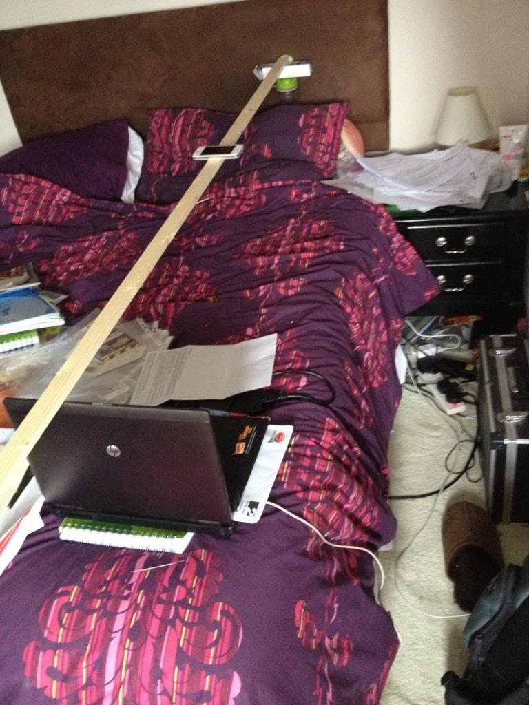
Monday, April 22, 2013
Making a new hotend heater
Annoyingly my replacement hot end for my solidoodle has failed again. it did last a lot longer than the original hot end that came with the machine, but it was fairly obvious that it would fail again.
The mode of failure is that the nichrome wire is getting too hot and melting through the Kapton tape, this is turn is making short circuits, and reducing the heater resistance, this is making more current flow, and the power to the heater is increased, I'm seeing a lot of max temp reached where the hotend starts to peak well in excess of the max temp permissible, (the max temp is to protect the peek)
But also the sudden rushes of current cause cause the power supply to stall, I've had steps being skipped, sometimes I've had axis appear to just re-home themselves, so instead of a single layer skipping, the entire model will just move two inches to the left have way through a print.
So this time I'm going to go all out and create a new hot end.
I'm going to base my design on the Jhead style heaters, with a block close to the nozzle, but instead of using a resistor I've decided to use a small ceramic heater.
Instead of tying my heater and barrel to the nozzle (which I may want to change to have greater or smaller nozzle widths) I'm going to stick with the M6 barrel of the solidoode, I'll stick with the removable nozzle, and I'll make a heater that can be screwed on and off just like the heatcore design could.
To start with I've located a 40w ceramic heater online that comes in a 23mm long 6mm diameter tubular package.
This will be my heater.
My block that will be used to store heat will be aluminium, (it's easy to acquire, relatively cheap -at least cheaper than brass)
The block will need to be at least 20mm wide to accommodate the 23mm heater, (it will not matter if 1mm sticks out either side -and this will help keep the wires away from the hot metal.
the block will be 10mm thick, this should mean that there is 2mm either side of the heater,
this will also allow for a 3mm hole to be drilled to install a grub screw to hold the heater cartridge in place.
The heater will be 2mm from it's opposite side of the block, and 2mm from the barrel of the machine, the barrel is 6mm wide, here will need to be at least 2mm on the opposite side of the heat block, (therefore the heater block must be 20mm x 10mm x 18mm, the most convenient size is 20mm x 20mm x 10mm)
Lastly the thermistor must also be installed in the printer, and must be thermally bonded reasonably well, to achieve this I plan to use heatsink style thermal compound and a second grub screw to ensure good contact.
Materials needed,
1 Aluminium block, (20mm x 18mm x 10mm) -I cut my block from a length of bar that was 20x10 x 2000mm
1 heater core, I bought mine as a 40w heater, but the measured resistance is actually 4.2Ohms, so it's actually a 34W heater.
3 grub screws I'm using M3 x 3mm
Thermistor -I'm re-using my original.
electrical connector - I'm re-using my original
Tools needed (at a minimum)
hacksaw -I'm using a B&Q value junior hacksaw -that cost 99p!
Drill
5.5mm Drill bit
2.5mm drill bit
6mm drill bit
M3 Tap
M6 Tap
Ruler
scribe for marking
so, here's the process.
First mark 18mm from the end of the bar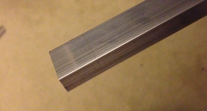
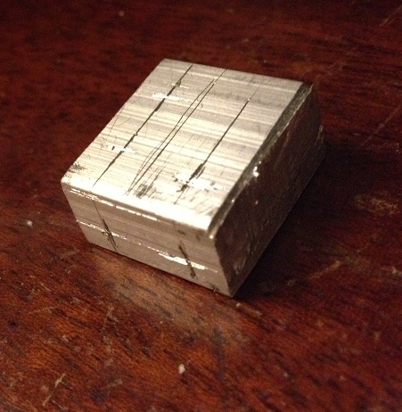
then cut off the aluminium block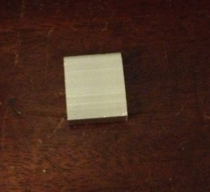
now you need to use a scribe to mark where you want to drill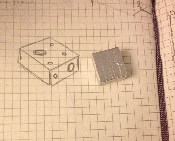
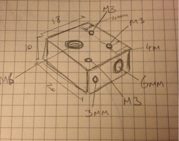
first drill the long hole through the block, start with a 3mm hole and then enlarge that to a 6mm hole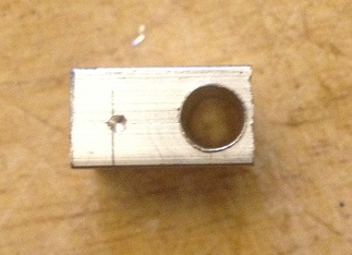
then drill a 2.5mm hole next to that, about 5mm into the block
now drill a 3mm hole and enlarge that to a 5.5mm hole (ready to be tapped for M6) in the face of the block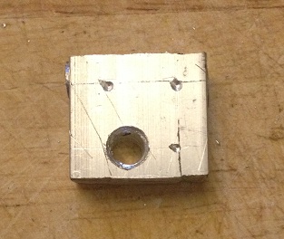
test fit the heater to make sure it fits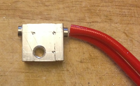
now using a 2.5mm drill bit drill three holes in the top face of the block.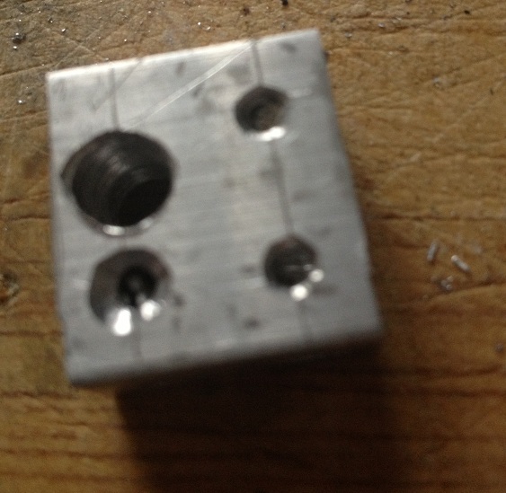
unfortunately my drill bit broke inside the last hole, so I put a different hole in the side instead -the drill bit is still stuck in the block
now you need to use the M3 tap to create a thread on the two 2.5mm holes that are drilled through to the 6mm hole, and also in the final 2.5mm hole, (this should be on the top, but mine is on the side thanks to the broken drill bit)
Then you need to use an M6 tap to create a thread on the 5.5mm hole that goes through the block.
now we come to assembly.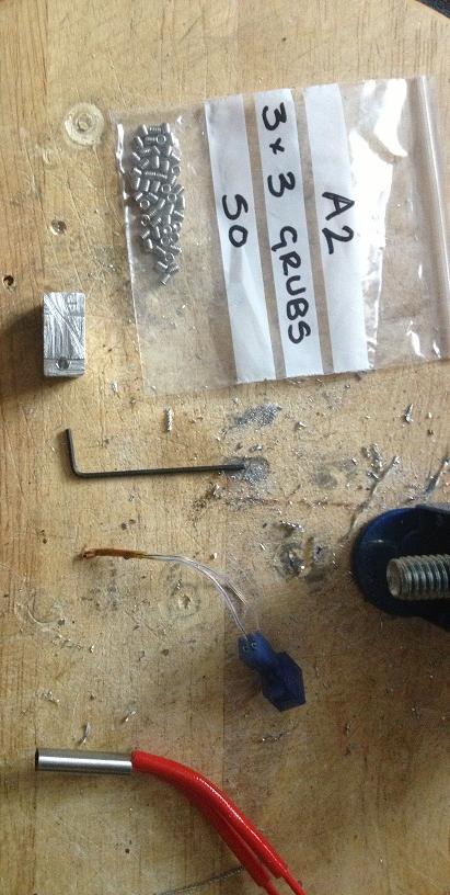
and the heater secured with two more grub screws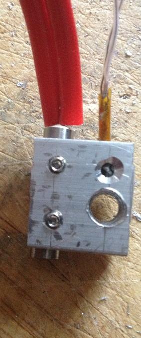
Now I've pulled the whole connector off the original green heat core wires, and attached it to the new red heater wires.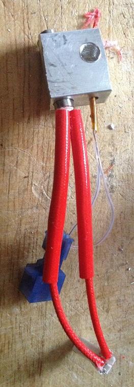
You need to remove the extruder from the machine, (the block catches on the carriage if you don't remove it to turn it)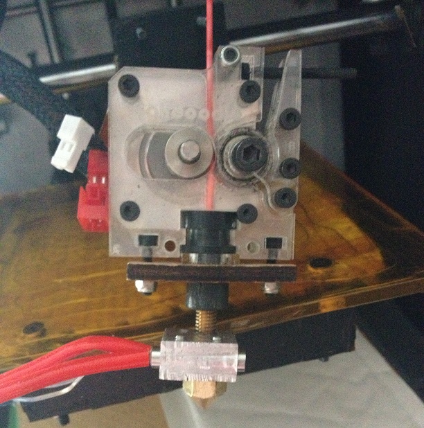
then you can screw the new heater onto the machine and replace the nozzle.
after that the only thing left to do is re-mount the extruder, re-connect the wires and start printing!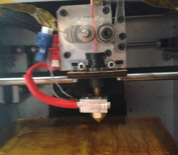
The heat-up time is more or less exactly the same, and the stability of the heater is actually probably a bit better than the original heatcore, (looking at the graphs in RH)
The mode of failure is that the nichrome wire is getting too hot and melting through the Kapton tape, this is turn is making short circuits, and reducing the heater resistance, this is making more current flow, and the power to the heater is increased, I'm seeing a lot of max temp reached where the hotend starts to peak well in excess of the max temp permissible, (the max temp is to protect the peek)
But also the sudden rushes of current cause cause the power supply to stall, I've had steps being skipped, sometimes I've had axis appear to just re-home themselves, so instead of a single layer skipping, the entire model will just move two inches to the left have way through a print.
So this time I'm going to go all out and create a new hot end.
I'm going to base my design on the Jhead style heaters, with a block close to the nozzle, but instead of using a resistor I've decided to use a small ceramic heater.
Instead of tying my heater and barrel to the nozzle (which I may want to change to have greater or smaller nozzle widths) I'm going to stick with the M6 barrel of the solidoode, I'll stick with the removable nozzle, and I'll make a heater that can be screwed on and off just like the heatcore design could.
To start with I've located a 40w ceramic heater online that comes in a 23mm long 6mm diameter tubular package.
This will be my heater.
My block that will be used to store heat will be aluminium, (it's easy to acquire, relatively cheap -at least cheaper than brass)
The block will need to be at least 20mm wide to accommodate the 23mm heater, (it will not matter if 1mm sticks out either side -and this will help keep the wires away from the hot metal.
the block will be 10mm thick, this should mean that there is 2mm either side of the heater,
this will also allow for a 3mm hole to be drilled to install a grub screw to hold the heater cartridge in place.
The heater will be 2mm from it's opposite side of the block, and 2mm from the barrel of the machine, the barrel is 6mm wide, here will need to be at least 2mm on the opposite side of the heat block, (therefore the heater block must be 20mm x 10mm x 18mm, the most convenient size is 20mm x 20mm x 10mm)
Lastly the thermistor must also be installed in the printer, and must be thermally bonded reasonably well, to achieve this I plan to use heatsink style thermal compound and a second grub screw to ensure good contact.
Materials needed,
1 Aluminium block, (20mm x 18mm x 10mm) -I cut my block from a length of bar that was 20x10 x 2000mm
1 heater core, I bought mine as a 40w heater, but the measured resistance is actually 4.2Ohms, so it's actually a 34W heater.
3 grub screws I'm using M3 x 3mm
Thermistor -I'm re-using my original.
electrical connector - I'm re-using my original
Tools needed (at a minimum)
hacksaw -I'm using a B&Q value junior hacksaw -that cost 99p!
Drill
5.5mm Drill bit
2.5mm drill bit
6mm drill bit
M3 Tap
M6 Tap
Ruler
scribe for marking
so, here's the process.
First mark 18mm from the end of the bar
then cut off the aluminium block
now you need to use a scribe to mark where you want to drill
(the measurement that is missing here is that the M6 hole is centred
9mm from the far edge)
first drill the long hole through the block, start with a 3mm hole and then enlarge that to a 6mm hole
then drill a 2.5mm hole next to that, about 5mm into the block
now drill a 3mm hole and enlarge that to a 5.5mm hole (ready to be tapped for M6) in the face of the block
test fit the heater to make sure it fits
now using a 2.5mm drill bit drill three holes in the top face of the block.
unfortunately my drill bit broke inside the last hole, so I put a different hole in the side instead -the drill bit is still stuck in the block
now you need to use the M3 tap to create a thread on the two 2.5mm holes that are drilled through to the 6mm hole, and also in the final 2.5mm hole, (this should be on the top, but mine is on the side thanks to the broken drill bit)
Then you need to use an M6 tap to create a thread on the 5.5mm hole that goes through the block.
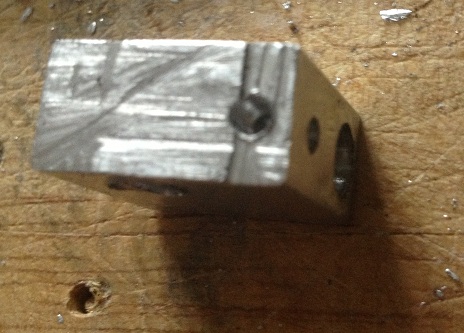
now we come to assembly.
the heater slides into the 6mm hole.
the thermistor slides into the 2.5mm hole.
the thermistor is secured with an M3 grub screw.
the thermistor slides into the 2.5mm hole.
the thermistor is secured with an M3 grub screw.
and the heater secured with two more grub screws
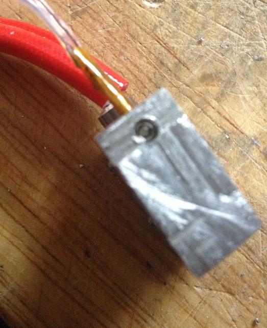
Now I've pulled the whole connector off the original green heat core wires, and attached it to the new red heater wires.
You need to remove the extruder from the machine, (the block catches on the carriage if you don't remove it to turn it)
then you can screw the new heater onto the machine and replace the nozzle.
after that the only thing left to do is re-mount the extruder, re-connect the wires and start printing!
The heat-up time is more or less exactly the same, and the stability of the heater is actually probably a bit better than the original heatcore, (looking at the graphs in RH)
Monday, April 15, 2013
Making a Lego Table
So this is a nice short post that details the Lego table that was made for my Daughters birthday.
It's a pretty simple idea, rather than having lego all over the floor, (not that this will stop that happening) a special lego table is created, where models can be created and worked on, perhaps over a number of days.
The basis for this table is a cupboard from Ikea that is a bit like those old school cupboards, there are some plastic trays that will be used to store the lego in.
On the top of the table base boards are glued to the top.
This table uses 32 x 32 piece boards, (three of them) and 16 x 32 stud boards, (4 of them) and a single 16 x 16 stud board
The total areas therefore is 48 studs wide (32 + 16) and 112 studs long (32 + 32 + 32 + 16)
there is an equal border, (about a 3 stud lego brick size) around the whole top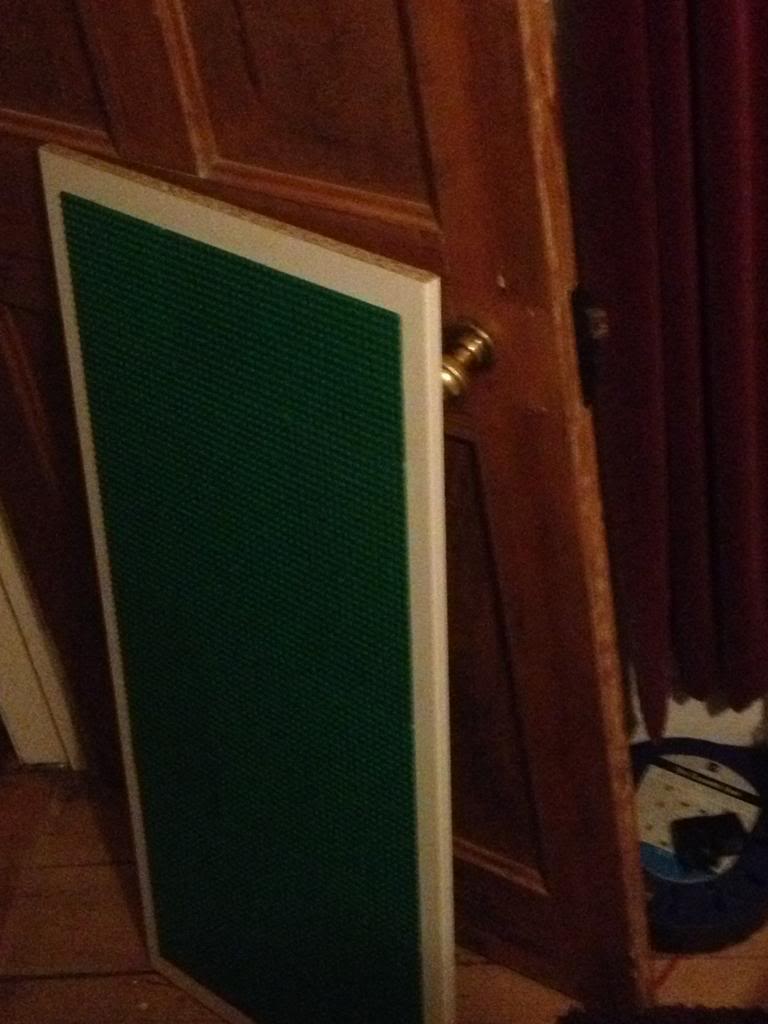
The boards were glue using solvent free evo stick (contact adhesive) glue. obviously a solvent based glue would melt the ABS plastic that is used to make Lego!
When the table is all put together it looks like this: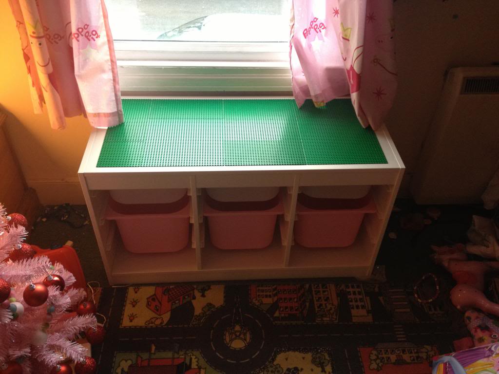
You can just about see the way that the boards are offset to try to minimise the lines.
Monday, April 08, 2013
Creo Elements - More gears (yes more) spur gears, helical gears and herringbone gears
So I've done a couple of blog posts now on making gears, first by creating just a section of the gear. then replicating it around an axis
And by creating a big gear with a single tooth. then replicating it around an axis
Now I'll look at a third and final way of creating a spur gear, and show how this is also the way you need to make a helical gear, (with diagonal teeth) and a herringbone gear, (with herringbone -like little arrows teeth)
Even though this tutorial will show now to create all the gear types it's worth looking at the others, mostly because I'm only introducing the tools used once. so the lessons do build on top of each other, also, it's good to know more than one way of getting a part made.
We'll imagine the same scenario as the last post, that we have two axles 50mm apart and want two gears to link them.
The gears mesh together, so again we'll have the raise teeth of the gear protruding the 26mm radius, and the reciprocating grove in the gear at 24mm.
This time draw a circle that's 24mm.
pull the circle into a cylinder 20mm tall.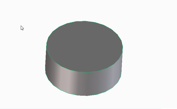
(you can pull to any height, but with the maths used later I'm using 20mm)
Now create a new work plane on that cylinder, draw guide lines for your tooth profile to be created, again at an angle of 5 degrees.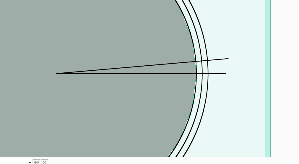
Once again draw a tooth profile onto the edge of the cylinder, your tooth crown should be 26mm from the centre.
Delete your guidelines that you've drawn and you're left with a single tooth on a cylinder again.
now clearly you can once again pull that tooth to 20mm height and replicate with rotational symetry, (like we did in the last two posts) to make another spur gear.
But this time I'm going to make a helical gear.
Select the helix add tool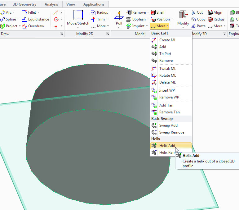
Select the axis as the centre of the cylinder part.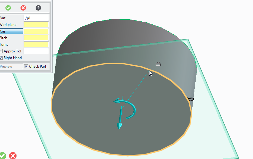
Now the pitch and turns are related.
Our part is 20mm high, therefore if we select 20 for the pitch and 1 for the turn, we'll get a single complete turn of the tooth profile all the way around the part.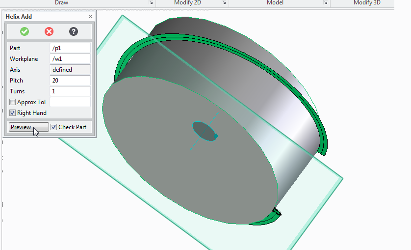
But we want a tooth that progresses about 5 degrees around the part.
To progress 5 degrees around the part we need 5/360 turns (roughly 0.01)
and to keep the same pitch to turn ration (to make the tooth reach the top of the gear) we need the pitch to change to 20/0.01 = 2000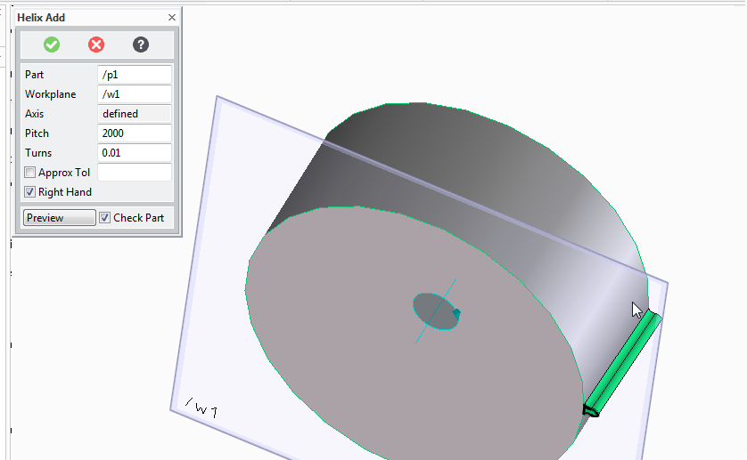
Now we need to mirror the part to create all the teeth.
since each tooth takes up 5 degrees we'll mirror 72 times, at an angle of 5 degrees.
Giving us a helical gear.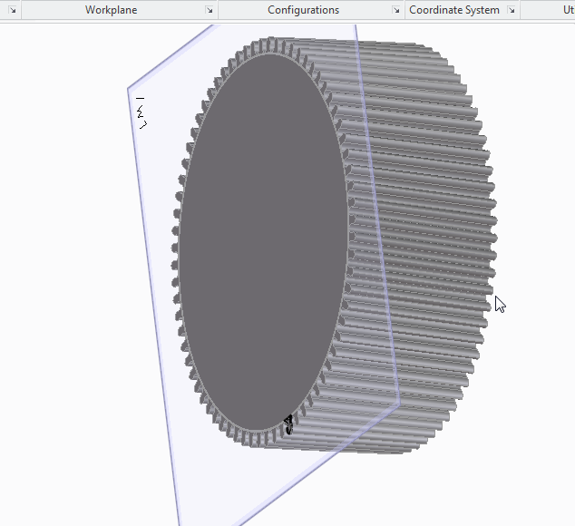
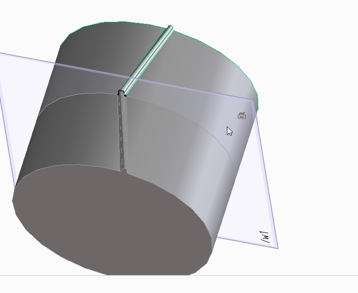
Now imagine that we want a steeper angle on those teeth.
go back to the part where there is just the outline of a single tooth ready to be added as a helix.
now imaging that we want the tooth to extend 20 degrees around the gear.
we need figure our the turns first.
360/20 =~0.04
then we need to figure out the pitch,
20 (gear height) / 0.04 (turns) = 500
Once again, use the rotational mirror tool to make 72 teeth with an angle of 5 degrees about an axis that is the centre of the gear.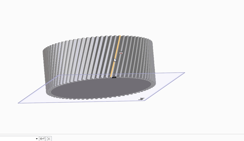
HerringBone
Alternatively.
Before mirroring the tooth rotationally, to create a herringbone gear mirror the tooth along the face first.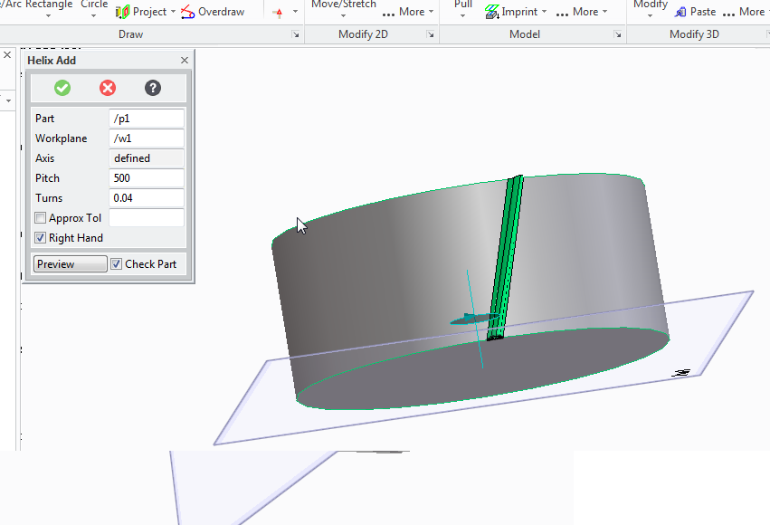
now you'll have noticed that mirroring creates a lot of individual parts. We're going to apply the rotational symmetry to the herringbone gear that we are creating, so we want to group the parts into a single assembally so that we only need to perform the mirror opperation once.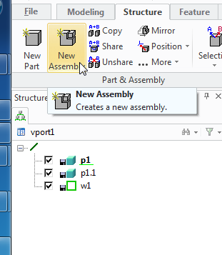
fter creating the new assembaly (a1) drag the two parts (p1 and p1.1) into the assembly.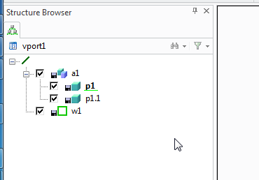
Now double click a1 you'll see the edge lines of the whole assembly are highlighted.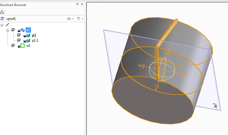
And apply the radial mirror tool to extend the gear teeth over the whole gear.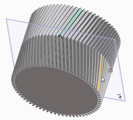
And by creating a big gear with a single tooth. then replicating it around an axis
Now I'll look at a third and final way of creating a spur gear, and show how this is also the way you need to make a helical gear, (with diagonal teeth) and a herringbone gear, (with herringbone -like little arrows teeth)
Even though this tutorial will show now to create all the gear types it's worth looking at the others, mostly because I'm only introducing the tools used once. so the lessons do build on top of each other, also, it's good to know more than one way of getting a part made.
We'll imagine the same scenario as the last post, that we have two axles 50mm apart and want two gears to link them.
The gears mesh together, so again we'll have the raise teeth of the gear protruding the 26mm radius, and the reciprocating grove in the gear at 24mm.
This time draw a circle that's 24mm.
pull the circle into a cylinder 20mm tall.
Now create a new work plane on that cylinder, draw guide lines for your tooth profile to be created, again at an angle of 5 degrees.
Once again draw a tooth profile onto the edge of the cylinder, your tooth crown should be 26mm from the centre.
Delete your guidelines that you've drawn and you're left with a single tooth on a cylinder again.
But this time I'm going to make a helical gear.
Select the helix add tool
Select the axis as the centre of the cylinder part.
Our part is 20mm high, therefore if we select 20 for the pitch and 1 for the turn, we'll get a single complete turn of the tooth profile all the way around the part.
To progress 5 degrees around the part we need 5/360 turns (roughly 0.01)
and to keep the same pitch to turn ration (to make the tooth reach the top of the gear) we need the pitch to change to 20/0.01 = 2000
since each tooth takes up 5 degrees we'll mirror 72 times, at an angle of 5 degrees.
Giving us a helical gear.
Now imagine that we want a steeper angle on those teeth.
go back to the part where there is just the outline of a single tooth ready to be added as a helix.
we need figure our the turns first.
360/20 =~0.04
then we need to figure out the pitch,
20 (gear height) / 0.04 (turns) = 500
Once again, use the rotational mirror tool to make 72 teeth with an angle of 5 degrees about an axis that is the centre of the gear.
HerringBone
Alternatively.
Before mirroring the tooth rotationally, to create a herringbone gear mirror the tooth along the face first.
now you'll have noticed that mirroring creates a lot of individual parts. We're going to apply the rotational symmetry to the herringbone gear that we are creating, so we want to group the parts into a single assembally so that we only need to perform the mirror opperation once.
Subscribe to:
Posts (Atom)