Monday, October 31, 2011

Electronics lessons: The Relay

So, a while ago we covered the switch, how contacts are made and how they are broken, the different types of switch that you could get, toggle switches and slide switches. but the thing is, all those switches relied on you pressing a button.

We talked about how the transistor acts like an electronic switch, but the problem here is that the transistor cannot handle, (as in physically, cannot handle will get too hot and melt) huge currents, also in some projects you may want to physically isolate some parts of the circuit away from other parts.

You may for example have a circuit that has parts exposed where you might touch them, but it's ok as it's very low voltages, but elsewhere in the circuit you may be using mains voltages to turn on a light, in this case what you need to use is a relay.

A relay is a kind of electronic switch. The traditional relay is made with two normal switch contacts,one of these is held in a fixed position whilst the other is on a stiff sprung arm, but is able to move.

Traditional relays have a electro magnet contained inside, when activated this electro magnet pulls the sprung arm towards it, either opening or closing switch contacts. The symbol for a relay is a small box to indicate the electromagnet with a normal switch symbol alongside this, the switch contacts are contained inside a dotted outline to show that they are controlled by the relay.

Monday, October 24, 2011

Changing Venetian Blinds

There are many reasons why you may want to change the slatted blinds in your house, perhaps you are re-decorating, changing the scenery, perhaps the old ones have been there a long time, or perhaps, like me, you have cats which are little bastards that chew everything they get near to.

Having chewed a couple of blind slats, the blinds now have to be changed, since I was doing this anyway it seemed only fitting that I should write and post up a small how to do this, there will be plenty of pictures.

Firstly, this is the damaged blind slats.


To remove the old blinds look at where the blinds are hung on the wall, these binds, (originally from B&Q) have a small sliding door that you open to be able to remove the top of the blind from it's bracket.

Once the door is opened the blind can be removed from this end, and will come out the other end without the need to remove the door on that side.

When you are buying the replacement blind you are pretty unlikely to find a blind that will fit your window perfectly, (you'd think in a fairly modern house where every house looks like the last, the people who make cookie cutter houses might have talked to the people who make binds and maybe decided on what a good window size was, but apparently that would have been too hard.

So start by measuring the width of the window (left to right) in this case the window measured 115cm you then need to measure the height of the window from top to bottom, this is called the drop and for the blind I'm changing the drop needs to be 103cm
Then you need to go to the shop and buy the closest fitting blind, in my case this was a 110cm wide blind with a drop of 180cm.

Once you've purchased your blinds, you'll then need to go about making them fit.
Making them fit width wise is pretty easy, (but very time consuming.)

I need to shorted my blind by 7cm, this means removing 3.5cm from each side.
Start by using a small hack saw to cut 3.5cm from each end at the top bracket part that holds the strings, then using scissors, but 3.5cm from each end of each and every slat -I did warm you it was time consuming!!
Once you're done altering the top bracket and the slats, you now need to shorten the bar at the bottom.

To do this you need to remove the plastic end caps -which should pull off, then as before cut 3.5cm from each end with a saw.

now that the blind will fit into the window recess, put the blind into the bracket, and the top and let the blinds go down, the drop of the blinds is still far too great for the window.

chose a slat that's a couple of slats lower than the slat that you think should go at the bottom, (the aim is to have a couple of slats sitting on the bottom bar so that the blind doesn't distort when you change the slat angles.) mark this slat, a big black marker pen will do the trick, or cutting it up with the scissors.

Now take the blind out of the windows and rest it on a large flat surface.
The bottom bar has a series of white plugs in it, these need to be prized out so that you can get the the pull strings for the blind.


once the clips are out, you should be able to remove the strings the hold up the blinds, which are held into the bar with a small knot. when you undo the knot the pull strings for the blind should come out of the bar.
the bar will now be held in the threaded ladder part of the setup that controls the blinds angle.
you can just slid the bar sideways out of this laddered thread.


Pull the main threads out of the slats, up to the slat that you marked, (clearly do take out the slat that you drew all over!) then pull the slats sideways out of the laddered thread.


now slide the bar into the place on the laddered thread where your marked slat was, and thread the pull strings back into the bar.
(if you cut the nylon pull strings, then make be frayed now. use a lighter to heat the frayed end of the nylon cord, then whilst it is still warm quickly twist it between your fingers.

Once you've threaded the draw cord through, you'll need to tie a small knot in the string so that the bar will sit on this and raise/lower with the string.

Then cut off the spare string. and remove all but about three of the laddered thread.

Now you can poke the end of the string into the hole in the bottom of the blind, twist up and poke in the dangling thin ladder threads into this hole also. then pop the small cap back on to hold the threads inside the bar.


Finally hang the blind into the brackets that were already on the wall, and adjust the draw strings as necessary.
(to adjust the draw strings pull the knot from the toggle and tie a new know further up the draw string for the toggle to rest on, and cut away the draw string that is spare.)

Finally, step back and admire your handy work. :)

the blind slats that were removed can be kept for the future in case the cats decide that they would like to have a chew on the blinds again :)


Monday, October 17, 2011

Fixing an amplifier 1

The problem with this amplifier is that the input jack is a little hit and miss.

When you plug the input in, there is a 50:50 chance if the amp will make a noise, wiggling or holding the jack seems to make the circuit complete, so it seems that the amplifier is working, but the jack is not.

However, along the way, I managed to break this amplifier more than it already was, and had to replace part that were non-standard with standard parts that I had to customise.


The amplifier in question is a Peavey Backstage amp, a tiny little guitar practice amp thing.
The basic problem is that sometimes you plug the guitar in and it works, sometimes you plug the guitar is and it doesn't work.
sometimes you plug the guitar in and it works, but only if you wiggle the jack lead around in the socket.

Basically, the input jack has for one reason or another seen better days, and could do with repairing.

Start by disconnecting the speaker wires, to ensure that you re-attach them with the correct polarity, (and thus correct phase) write down which terminal the white wire comes from and which wire the blue one comes from.
Next, remove the four screws on the top of the amplifier, and sliding out the tray that holds the electronics, push from the front, to the back.


next remove the wiring for the transformer, and output power transistors as these are mounted on the chassis case, and remove the circuit board from the case.

In order to remove the circuit board from the case, you'll have to remove the plastic knobs from the front panel, these just pull off, or at least should just pull off.

This is where the first "challenge" of the build started, when removing the knobs the potentiometer came apart on two of the controls!


This is no trouble, all I needed to do was replace the potentiometers. I could see that they were the small type, (mini pot) as the body was about the size of a 1penny piece, (instead of the regular size of just smaller than a 2penny piece).
looking at the body of the pot I was able to determine that I needed a B47K (linear 47k pot) and an A10K (I think) (Analogue 10k pot)
So I nipped to the shops and bought 2 mini pots of the correct size.

the only trouble is, rather than receive pots with a stubby shaft with straight splines attached, I received a pot with a long smooth shaft. Alas, I found that I could buy small splined pots, if I were willing to wait a few weeks and pay twice as much, or I could use the pots that I could get and make them fit.


to make them fit, I need to shorten the shaft, and then put a texture into the shaft such that the plastic knob will have something to grip.

so, step 1,
Put the pot next to one of the existing ones on the board, use a marker to mark the length that the shaft needs to be.

step 2, cut the shaft.

step 3, hold the newly shortened shaft in a vice, and using a needle file score a spiral pattern into the shaft.

step 4, reverse the spiral pattern to give a knurled looking finish.

Here's a picture showing an unaltered pot next to my newly customised one.

Now remove the old broken pots from the amplifiers circuit board, (Don't do this at the start, else you may forget which is meant to be the analogue one and which is the linear one!)

now solder in your new pots.


Now it's time to replace that jack socket.
simply remove the jack socket by de-soldering it's 4 legs,  pull out the part and solder a new one in!

screw the circuit board, back to the chassis.
plug in the transistors and transformer again.

slide the amplifier tray into the back of the amplifier.
insert the four screws into the top that hold the tray to the amplifier body.
re-attach the speaker.
now test the amplifier.

Thursday, October 13, 2011

Electronics lessons: Pulse width modulation

Right now, this lesson is going to be useless.
Because in this lesson there is no application.
What this means is that this is another lesson of reasonably boring theory,
All I can say is hang in there, there are plenty of applications for pulse width modulation, so this is an important thing to get your head around.


Pulses
Often times in anything modern, we take existing words and try to shoe-horn new meanings into them, like how we describe an integrated circuit as a chip. it's not a chip really, it's definitly not a potato product, and it's not a small piece of anything really, (yes it is a small piece of a silicon wafer that was removed during production) but the name is poor.

The word pulse in pulse width modulation however is perfectly used.
imagine pulse in your wrist, goes on, goes off, goes on, goes off.
the pulse button on a blender, (used for turning on and off).
something that is pulsating.

An electronic signal that rises and falls between logic levels is perfectly described as a pulse.


Firstly:
All pulses have a rising edge, (where the voltage rises).
All pulses have a duration, (marked as t on the above diagram).
All pulses have a falling edge, (where the voltage falls).

There is also a period of time when the voltage is low.

A series of pulses is a pulse train.
pulse trains may have a defined repeating interval, -but this may also not happen.

pulses may not appear regular as above, the off time may be longer or shorter, and the pulse duration may vary. pulse trains do not have to appear as signals with regularity, indeed in pulse width modulation, the width of pulses changes specifically as a way to convey information.


One of the more popular uses of pulse width modulation is servo control.

Servos (as in the little hobby RC servos) are controlled by Pulse width modulation.
basically, a short pulse tells the motor to move all the way to the left of the travel, whilst a long pulse means move all the way to the right.


In servo control, pulses may be between 800 microseconds, and 2200 microsecond, with a pulse interval of 20 milliseconds.

To make a servo move all the way to the left extreme of travel, you need to:

Turn on the pulse, (rising edge)
Wait for 800us (pulse width)
Turn off the pulse, (falling edge)
wait for 19,200us (off time) - to make up the 2milisecond pulse interval expected.
repeat

To make a servo move all the way to the right extreme of travel, you need to:

Turn on the pulse, (rising edge)
Wait for 2200us (pulse width)
Turn off the pulse, (falling edge)
wait for 17,800us (off time) - to make up the 2milisecond pulse interval expected.
repeat

Varying the duration that the pulse stays on for, (between 800us and 2200us) causes the arm on the servo to go to any position to control.

for example, to centre the arm, you need to send pulses with a duration on 1.5miliseconds, 1500us

Sunday, October 09, 2011

Electronics Lessons: The Amplifier

OK, we looked at a transistor amplifier, and will go on to look at operational amplifier circuits.

One thing that I didn't do was measure how "good" these amplifiers were. I think that everyone has had a bad experience with an amplifier at one time of another, something that just sounded weird, and not quite right. but perhaps you didn't even notice until you heard something better, then went back and listened to the same amplifier again.

So lets look at amplifiers on some more detail, explaining some of the words used.
-this is just a quick guide to some terms that you will find in amplifiers, their use and design.

Distortion (clipping)
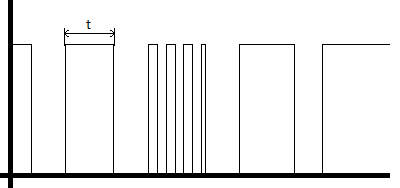
The easiest way to explain clipping distortion is to look at what causes it.

Imagine that you have an amplifier that have a positive supply voltage of +5V, and a negative supply voltage of -5V.
The amplifier has an input signal applied to it of +/- 1V peak to peak and a gain of 2.

The input is a lovely sine wave, rising an falling between 1 and -1 volts,
The output wave is a similarly lovely since wave between 2 and -2 volts.

Now if you increase the gain to six.
you would expect the output wave to now rise and fall between +6 and -6 volts in the same perfect sine wave, except, it can't the supply voltage to the amplifier circuit is only 5v so instead the wave goes up to 5v, then there is a plateau where the top of the sine wave should be, before it levels out and falls to -5v and plateaus again where is should be falling below this.

You are effectively over driving the amplifier, trying to force it to amplify beyond it's means. the top and bottom of the signal gets clipped off.

Headroom
headroom is a weird one, it's not something that you're ever going to see on a data sheet, because it's just a made up figure, it's something that you either have, or don't have, but I include it because I feel that it's important.

Headroom is a measure of how much power you have left in the amplifier. For example: say you need at least 100W of sound to fill a particular room with sound, that would suggest that you need to buy a 100W amplifier right?

Well sort of yes, and sort of no, if you need the full 100W of the amplifier, then you'll be turning the amplifier up full driving it to it's limits (and possibly beyond and possibly clipping the signal) then you've not specified a big enough amplifier. Sure you fill the room with sound, but what about the quality of that sound?

If you need a 100W amplifier to fill a room with sound, you're better suited to buying a 200W amplifier, in that way you only need to turn it up half way to get your 100W of power, the amplifier is operating well within it's limits, you won't be driving components or circuits to their limits and thus will get a cleaner sound.

Frequency Response.
The frequency response of an amplifier shows how well it responds to particular frequencies, If you look back to the floor standing speaker project the frequency response of speakers was discussed in reasonable detail, with amplifiers frequency response tends to be less determined by mechanical considerations, (as with speakers, and how much mass/air/distance can be travelled, and more by electrical characteristics of the components used, for example a capacitor has reactance, (right now you can think of that as resistance that varies with frequency. inductors also have a resistance that varies with frequency. This means that certain ranges signals will pass through the components easier than other signals, (with a different frequency range), and the amplifier may have superior gain at a given frequency range, or indeed an entirely reject other frequency ranges.

This differing frequency range in amplifiers is why, (for example) guitar amplifiers, (higher frequencies) are different to bass guitar amplifiers, (lower frequencies), which are again different from keyboard amplifiers, (which need a much broader frequency response.

Bandwidth
The bandwith of am amplifier describes a frequency range at which a given amount of gain can be produced, outside of the bandwidth of an amplifier gain drops off, (both above and below the frequency range). Bandwidth and frequency response, whilst different, may be used interchangeably in marketing literature

Total Harmonic Distortion (THD)
Total harmonic distortion, the absolute bane of anybody shopping for an amplifiers life.
kind of important, kind of a rubbish figure, it says so much and yet not nearly enough.

The basic premise is:
when you alter a signal, (say in an amplifier), each component may distort the signal slightly, and those distortions are usually in the form of adding harmonic compnents to the wave.

What this means is that for a signal, Ahz, there may be distortions at Bhz, Chz and Dhz, (where BCand D frequencies are harmonics of A).

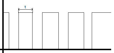
It's possibly worth knowing that a pure sign wave plus decaying harmonics of it's fundamentals eventually sums to a square wave - but I'll explain that one another time) -just trust me, a sine wave is like a pure sweet whistle, a square wave is like a buzzer. -so you can see how adding harmonics to a signal, (and distorting that signal) can make it sound bad?

Anyway... the Total harmonic distortion is described as:
the power of all the added harmonic wave forms, divided by the power of the original source wave form (after amplification).

so if we have a output, amplified wave form A at 90W
and the harmonics at B - 5W, C = 3W, D = 2W

we have 5+3+2 =10 / 90
Therefore THD = 0.111
As you can see, what we're saying here is that you put a signal into your 100W amplifier, of the signal that comes out 10watts of it is just distortion. (whether that distortion sounds good or not is anyone's guess).

Further compounding the problem of THD figures is what type of distortion is added?
Crossover distortion adds harmonics in the levels that are audiable, (and don't sound "good").
whilst clipping distortion, produces more of a square wave, (like an overdrive guitar pedal), yes adding distortion, but adding it in such a way that some may actually find it pleasing to listen to, - and most of the distortion may even be very high order harmonics that are not even audible!

(in short, THD is useful when combined with lots of other information, but at the same time totally useless on it's own!)

Tuesday, October 04, 2011

Electronics Lesson: Breadboards

When you're first starting out making a project a bread board is an invaluable tool, it allows you to quickly throw together circuits and test things out.

To a person that's never seen one before they can be a little strange, it is after all just a little plastic board with a whole heap of holes in it.

But it's the copper tracks underneath those holes that make this useful.

Under the holes there are a series of U shaped coper tracks, when you push a component into a hole it makes contact with one of these tracks. you can then attach another component to another end of this track and you'd connected two components together.

Photobucket
The picture shown above shows the way in which the tracks flow.

At the very top and bottom of the board you have a blue line and a red line, these are to indicate power rails, (what they are normally used for). These run from left to right.

You see how the lines are solid? this indicates that the power rail runs the entire length of the board, if the line has a gap in it, this indicates that the power rail also has a break in it, (thus you can have 8 power rails instead of the 4 on this board, (2 at the top, 2 at the bottom)

The holes in the middle run from top to bottom. the only gap in these rails is the big break in the middle of the board. this big break is the width of a standard small chip, (like a 741, or a 555).


Just as a foot note:
the reason it's called a breadboard is because before this nifty little plastic board with copper tracks was invented people use to use either actual breadboard, (big wooden kitchen chopping boards).
they would use a screw, with a screw cup, then trap wires between the breadboard and brass screw cup to create electrical connecttions.
Even though it's no longer a wooden board, the name has just kinda stuck.