Monday, January 28, 2013

Electronics lessons: More on Logic gates

So a few months ago, I took a look at making gates with transistors
http://ah-screwit.blogspot.com/2012/10/electronics-lessons-making-gates.html

This post was a bit simplistic, but the logic was easy to follow, the idea that a transistor would conduct when on. (effectively being able to sink current from the output connecting the input of whatever came next to ground.) -or the transistor could be off, meaning not conducting so the output was connected to Vcc and the output was high.

This was the basic block of all the gates saying that we could run transistors in series to make the NOT gate into a NAND gate, or provide two connections to the base to make a NOR gate.

The trouble is, whilst in theory this will work, in practice there is not enough voltage gain, and over a series of make stages the signal will become weak.
The long and the short of it is that these simple single transistor gates are not real gates at all.

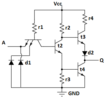
When I was talking about binary reduction and saving gates, you may think so what, I saved a NOT gate, that's only 1 transistor. but in reality. it's actually 4 transistors:


What you see here in a NOT gate.


It looks a little complicated and certainly the transistor T1 looks like it's connected the wrong way.

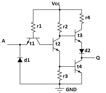
But it works a bit like this.
With a logic Low at the input.

T1 is clearly on, it's base is connected to Vcc,
Current flows from the base of T1 to the emitter, and flows to the logic low (ground).
the base of T2 is low, so T2 is off,
Since T2 is off we can see that the voltage at the emitter of T2 is low, so T4 is off, (output is not connected to ground through T4)
we can also see that since T2 is not conducting that the voltage at T2 collector is high, this is the base of T3, so T3 is on, conducting in the saturation region, and thus the output is high.

Logic low at input = Logic high at output.

Now consider what happens when the input is high.

T1 base is still connected to Vcc, so this transistor is still on and conducting, but this time rather than voltage flowing to ground at the input voltage must flow to ground through the base of T2, out the collector of T2, and to ground through R3.

so the Base of T2 is high, this turns T2 on.
this makes the T2 collector low and thus T3 it not on.
it makes the base of T4 high, so T4 is on. and connecting the output to ground.

logic high at input = logic low at output

So you see saving 80 not Gates doesn't save 80 transistors, it saves 320 transistors.


NAND
Funnily enough, with the basic transistor NAND gate we just stuck a transistor in series with the transistor making the NOT gate, now we put a second emitter in parallel with the first emitter.

We can't just put a transistor in series of parallel so we use a second emitter, (which is essentially just a second doped region on the silicon substrate.

This works exactly the same as the not gates, but instead of the base current for T2 being either grounded or supplied by THE (singular) input, it's not possible for it to be grounded by either input.


Again, an AND gate is made by connecting the output of a NAND gate to the input of a NOT gate.


Monday, January 21, 2013

Making a coat stand for a child

So I thought it was about time I finally wrote up the build of a coat stand that I made, (about 2 years ago).

The idea for this coat stand was sent to me by my friend who said I should make one for my daughter. I forget the exact link to the inspiration, but I do remember it was on Ana Whites website called "Knock off Wood, free woodworking plans for furniture http://ana-white.com/"

If you have a few days you should definitely check out that site, it's chock full of amazing furniture, includes plans.

You don't have to follow the plans, you can be like me and decide to make your own plans up in your head to build approximate versions of stuff on the site.

Anyway, now that I've covered where the idea came from it seems only right to give a little background.

Design
At the time I made this coat stand my daughter was about 3, she was getting to an age when you should care about your stuff, and start hanging up your coat etc, but not yet at an age where she could reach regular height coat hooks.

So the solution was obviously to build her a coat stand more suited for her.

This means that it should have pegs reachable by a 3 year old who stands about 3 feet tall, (so the height of the stand is about 4 feet, so she'd have to reach up at the start, but would not immediatly outgrown the stand.

I decided that the coat stand would need four pegs that would be at her current arm height that she could hand coats on, and a further 4 hat stand type pegs, to put hats on of course. As she grew the hat stand pegs would eventually become coat pegs.

So the parameters for design are:
four coat pegs, at about 3 feet from the ground, four hat pegs about 1 foot above the coat pegs, a stable base is a must.


Materials,
I decided that I'd use softwood to make this coat stand, it's easy to work with, and has a variety of finishing options from plain no finish, or varnish, to any colour as it's easy to paint.

The pegs I decided would be made of dowel. (12mm dowel so that they would not easily snap)

To build with nice proportions of 12mm diameter dowel pegs I decided that 48mm square pine was the best wood to use.


Onto the build
So the biggest gripe I had with the materials was the condition that it was in. I bought square planed timber from Wickes, this should be ready to go. if I'd bought rough sawn wood I'd agree that imperfections were ok.

So the first job was to inspect your materials and work out what I could do to cut out imperfections. like this:

Once I'd decided the best cuts for the wood (and there is no exact science for this that I'm aware of) I started cutting, setting the blade of my saw to 45 degrees I made a cut around 14 inches down the length of the wood.
then set the blade back to 90 degrees to make the next cut again about 14 inches down the length of wood.
This will gave me two bits of wood, with one square cut end, and the other end cut at 45 degrees.

Repeating the above gave me four of these. these will be the legs of the coat stand.


Next I made a 45 degree cut in the remaining (approximately 1 meter) length of wood.
Then flipped it over and made another 45 degree cut, then 2 more cuts and I had a square point.

I did this at the top and the bottom


Next I marked a ring about 1.5 inches from the bottom of the base of the point, this is where the legs will attach.


And a further ring about a half inch above that, (and another about an inch after that)


The centre of these lines are drilled with a 6mm drill bit, (ready to recieve a dowel peg to make a strong joint)


 Back to the legs.

Clearly the 45 degree cut is what will butt against the centre poll that I've been busy marking and drilling and making pointy.

But the legs do need some further work, and the moment the base will be the corner of the block of wood.

so I set my saw back to 45 degrees and cut an angle in the opposing direction to the mitre that will face the centre poll, then I cut again to smooth off the top of the leg.


I now marked and drilled the long mitred face of the leg, to recieve dowel pegs and glue.


Now I did a dry test of matching the joints (A dry test is where you put it all together without glue, this allows you to make any final adjustments before it's too late!!)


Finally I put dowel pegs and glue on the joint.
I set the first two joints against a table using wooden blocks screwed to the top to clamp it in position.
The final two legs were arranged with the blocks clamped to the centre stand, then the leg clamped to the blocks, (allowing the odd angled leg to be clamped to the stand)


Finally I drilled 12mm holes in the stand at about 4 feet from the floor. a hole going straight through, and another hole about an inch higher going through the other way.

Then I glued an 8 inch length of dowel into the holes, (with 3" sticking out of either side")

The hat pegs were drilled into the top of the stand, (about an inch and a half from the top, so the pegs are about as far along the centre poll as the legs are up it).

I don't have a drill press with a moveable table so I used a set square, and roughly lined the drill up to drill coat pegs at an angle into the top of the stand.


Lengths of 12mm dowel we then glued into these holes.

Finally the coat stand was painted a pastle pink colour.


Monday, January 14, 2013

Working with different Architectures and operating systems.

One thing that I mentioned in the index post I did at new years was that I had a raspberry pi, cool.
something I said a long time ago was that I had a small box called an Emprex ME1 media centre, again cool

I also have a laptop, Cool...

Except, working with all of these can be problematic.

At the end of last year I started talking about client/server software and noted that if you want to program network enabled programs that Linux is a good place to start building programs for.

This is not because I'm some kind of evangelical free software nut case who thinks that bill gates should die.

Because I'm not, I make my living working with and supporting Microsoft software.

The reason that I think that you should learn to program for sockets on Linux is because it's easier. it's how most systems do it. it's how embedded libraries work. Microsoft are really on their own on this one.

Anyway... -not the point I'm making here.

the point is that my media centre,
runs Venus Linux, on a 200MHz MIPS processor.

My raspberry pi runs raspbian on a 700MHz ARM processor. (though I might try RISCOS or plan 9 eventually).

My laptop runs windows 7 64 bit.

and that's where the problem is...
My laptop is a 64bit big endian machine running Microsoft software.

My boxes I want to create projects on are 32 bit little endian machines.

The operating system of the machines is different, the byte order for storage on the machines is different.

This means that I can't compile software on my laptop, and expect it to run on the machines.
even if I run Linux inside of VMWare player, I can create a binary that would run on Linux systems on x86 processors. but not my Raspberry pi on ARM, or my media centre on MIPS.

These machines couldn't be more different if they tried.
and that is why making them all work together is going to be such a joy!

I'm going to spend some lessons in this new year investigating ways to code across platforms, and how to set-up Linux machines, so that I can make these boxes a little bit more than expensive toys.

Monday, January 07, 2013

2012 post index

So it's been a pretty busy year on this blog, not so busy for actually making stuff, but pretty busy on the basic fundamentals of how things work that will allow people to design and make their own stuff.

I ended last year by promising to move the coding lessons into a space of embedded programming, that never really happened, but I'm going to try and make it happen this year.

This was the year that I decided to stop hanging around waiting to get around to building a 3d printer and decided that I'd buy one. probably not as fun as building my own and certainly not as informative, but definitely the best way to be able to print stuff for projects, instead of making a whole new project.

As I did last year, I'm just going to stop a moment and create a page that looks back over the last year and what I've written about here.

So the first thing I did was a round up of the previous years projects and posts, I think that this is a pretty good way to re-cap things, let me plan what I want to go onto make, or explain in the coming year.
Same post different year 2011 post index

This was also the year that I got myself a 3d printer, and I think the year that 3D printing finally became affordable to the non-hardcore enthusiast. There are people out there who believe the fused filament 3D printing is the future and the answer to all life's problems, that these should be in every home, and shipped out to rural Africa. I don't.
I don't think that Fused filament 3D printing will ever be a consumer technology suitable for every household, it's fiddly, things go wrong easily. you have to know what you're doing, modeling anything good is complicated, each printer, and even each roll of filament might have slightly different parameters that it operates well at.

3D printing

In light of having a 3d printer, I have written some posts about 3D printers:

When I ordered the printer
A basic guide to 3D modeling (making a calibration object
The 3d Printer finally arrived
Setting up the printer: Levelling the print bed

I've also made 3D printing projects:

Projects
Fixing the printer
Remaking and improving parts of the printer
Finaly making something on the printer

As well as regular electronics or woodwork projects.
Fixing an amplifier
Making a geeky notebook
Making another red-light torch
Installing a computer in a car!
Fixing the amplifier again
guide to splitting a house antenna
Making a towel ladder

General Stuff
I decided to branch out a little and write a guide to RAID in computers, at some point I have made this blog a strictly making sort of blog. but I like computers also, and I thought that my blog, which is the idiots guide to putting shit together, should involve something on putting together computers.

A short and sweet guide to RAID

I also did a tutorial post on counting in different bases, this was mostly so that future code and electronics lessons would make more sense. -I only really want to explain a principal once, not keep repeating myself. generally if you read a lesson and it makes no sense, then it's probably because you skipped a lesson.

A short and sweet guide to counting in different bases

Coding
C and Pointers
Using the malloc function
Accessing files
Writing files
structured data types
model of network software
Dealing with errors
creating a server program
Creating a client program
The code lessons I did this year have had more complex themes about them, they are still very basic, but they've moved on from this is an integer to looking at memory access, arrays etc, working with files, and looking at complex storage structures such as structs. and this is kind of my point about following things in order. when I was making speakers, I published a lesson on French polishing before posting the walk through of the build process, I did that because French polishing was needed to complete the speakers and I didn't want to need to repeat stuff. or go too far off the point.

The same with the coding lessons. if you miss structs out, then you have a problem when you come to sockets since the connection parameters are stored in a struct.
 

Electronics Lessons
Finally I did a lot of electronics lessons posts this year.
I started by introducing a few more components, and posting a theoretical home automation system to turn on lights and heating.
Then I looked at building power supplies for projects using transformers.

It's almost embarrassing that it's taken me nearly two years to finally cover the 555 timer. and to introduce op-amps and circuits for both.

After introducing these components I started getting into digital systems, logic and gates, and introduced a few tools for designing systems, and went through from start to finish a binary - hexadecimal display system using 7 segment displays, and exactly how to minimise logic circuits, both in terms of expression, and in terms of gate re-use when building larger system.

Looking at modulation types
Investigating relays
Introducing thermistors
Introducing Light dependant resistors
Basic analogue control for home automation
A look at the transformer (sadly not the robot in disguise"
Rectifying diode bridges
looking a transistors in long tailed pair configuration
Simple power supply circuits
introducing op amps
Simple op-amp circuits
More simple op-amp circuits
Zener Diodes
More simple power supply circuits
Simple power supply circuits
introducing the 555 timer
Looking at the whetstone bridge circuit
Introducing Digital logic
How to write logic expressions
How to reduce logic expressions algebraically
How to investigate logic with truth tables
Using NAND as the universal gate
Reducing logical expressions graphically with karnaugh maps
creating a logic circuit to convert binary to hex display
reducing gate count by building in blocks
making gates from transistors
Reducing logic expressions with lots of terms.

So, in this coming year I am hoping to do a few projects involving the Raspberry pi that I got for Christmas, introduce a few more logic circuits, do some coding lessons on Micro controllers and write up a few projects that I did last year. (and the year before in some cases).

Happy new year!