Actually this is a pretty fast repair, my print stopped printing at about 10:30, and I was printing again by 1, certainly faster than waiting for a new hot end...
Anyway... here is the process, I thought I'd document the process as the only other hot end pictures I can find on solidoodles support forums are a resistor type, (in the hot to clear blocks thread) there is also mention of a 10Ohm resistor, and my machine appears to be different.
First, how to determine if your hot end isn't hot:
The first you'll probably notice that your extruder is in trouble is that you'll start getting a message appear saying "prevent cold extrusion" this is a limit built into the firmware, if the hot end temperature is below (or reported to be below) 170 degrees C the extruder won't function. that's because the ABS won't be melted, if you ran the extruder stepped at this temperature all that'd happen is the gear would stick, and wear a little grove into the filament, then it won't grip. then when the hot end does come up to temp, it won't be able to move the plastic, the plastic will spend too long inside the extruder hot end, then it'll burn and clog.
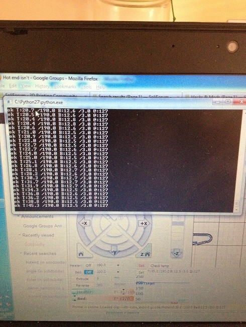
so you get the message that your hot end it's hot, have a look at the previous readings for temperature.
If the temperature has suddenly dropped from say 200 down to 0, then you should suspect the thermistor.
If the temperature has steadily declined, then you should suspect that the heater is broken.
Another quick and dirty way to test this would be to turn the heater off. monitor the temperature of the printer and apply an external heat source to the hot end, you should see the temperature rise. -if this happens you can confirm that the thermistor is OK, and it's the heater that's broken.
Having determined that your hot end is broken, you now need to figure out why.
Tools you'll need for this step is a multimeter.
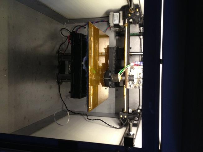
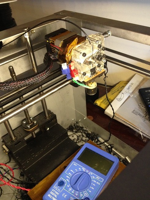
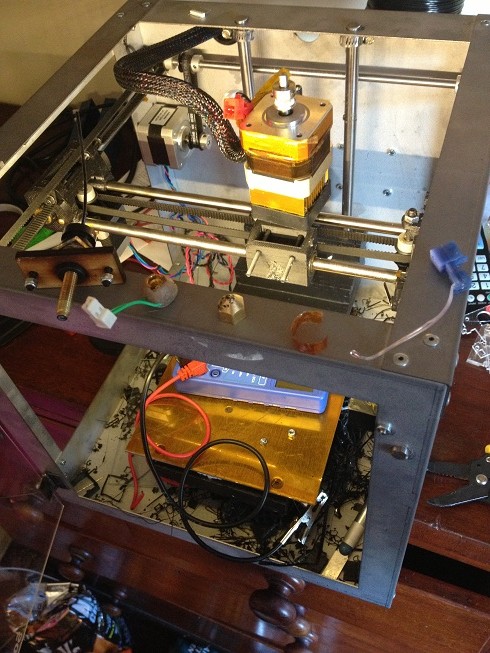
start at the back of the machine,
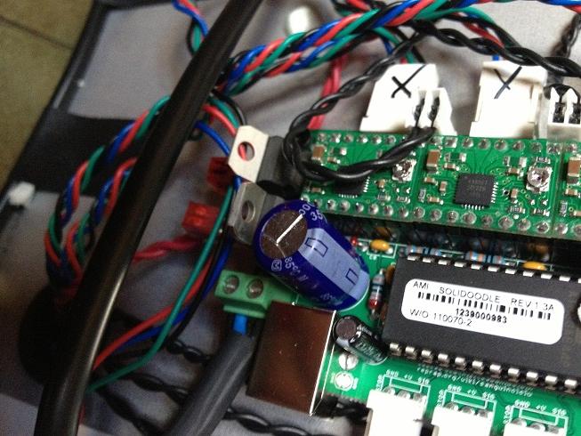
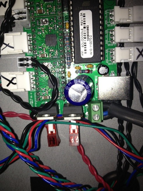
look at the circuit board, at the bottom you should see two red connectors. you are interested in the one on the left hand side, (marked H in this picture).
unplug that connector,
set your multimeter to read volts.
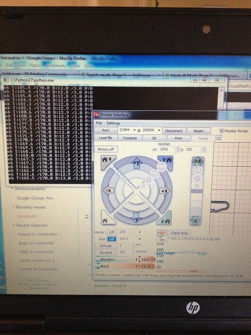
Tell the machine to turn the extruder on.
measure the voltage at the pins on the circuit board. you should get 12v.
if you don't get 12v, (and everything else in the machine is working), then you've got a problem with the main board.
If you do get 12v here, time to move on to the next step.
leave this cable unplugged, and unplug the hot end part of the extruder. (the red plug in the picture below)
there are a few possible out comes here.
Main board connector 1 - hot end connector a = 0 ohms AND
Main board connector 1 - hot end connector b = infinite ohms
This is good. it means that the wire you're measuring is intact and fine.
now check the other wire in the same way.
if the results appear the same, (one wire no connection, the other wire 0 ohms resistance) then the main board to heater part of the set up is working fine.
other possible combinations are:
main board connector 1 - hot end connector a = 0ohms AND
main board connector 1 - hot end connector b = 0 ohms
this means that there is a short in the cable somewhere, perhaps it's been rubbing against the case and the insulation has worn and shorted.
and the last possible combination
main board connector 1 - hot end connector a = infinite ohms AND
main board connector 1 - hot end connector b = infinite ohms
these past two scenarios mean that you need a new cable to go between the main board and the heater.
Assuming that your main board is fine, and your cable is fine.
now check your heater element.
leaving your multimeter on ohms put one probe on each wire.
the hopeful result should be to read a low resistance. elsewhere on this forum, the figure is listed as ten ohms, however, it may also be 6 ohms. (depends on what you have)
anything much less than 6 ohms, implies that there is a short. anything much greater than ten ohm, (like the 16,000 Million ohms mine read) implies a broken wire somewhere.
if you have a broken heater, then you have two courses of action.
buy a new one, or fix your existing one.
fixing it is actually easier than you might imagine.
tools you will need.
A 2.5 mm hex wrench.
a soldering iron + solder
a craft knife/exacto knife
a roll of 1/4" (6mm) Kapton tape.
scissors (for cutting the tape)
1 adjustable spanner (or whatever size your nozzle is)
1 plumbers wrench, (those adjustable pliers type things)
1 length of nichrome wire.
the stock solidoodle uses AWG 31, (however you can change this for whatever you want).
(indeed I'm actually going to recommend changing this -I'll say why later -there are pro's and cons.
So,
Step 1.
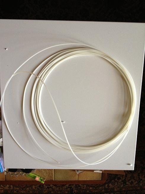
cut the filament,
you already have the heater unplugged, now unplug the thermistor (blue) connector. the hot end has now been freed from it's ties.
Step 2
take the extruder assembly from the X carriage, (undo the two hex nuts from the read that go through the X carriage and emerge at two m3 bolts right near to the plastic (peek) part of the hot end.
Step 3
Take the extruder assembly, (the clear plastic part) off of the stepped motor, (the four hex bolts that are equally spaced around the motor.
Step 4 (you require some space here - unless you've taken the extruder apart before plenty of times and know how it goes back together)
Remove the bolt that secures the spring at the top.
place the bolt, small washer, spring, small washer and large washer in a neat row. (so you remember the order that they came apart in.
Next remove the bolt that holds the tension arm in, (your extruder will now only have two bolts holding it together.
carefully remove the nuts from the ends of these bolts, (don't pull out the bolts!!)
now, turn the extruder over.
remove the back piece, put this down on a table, remove the next piece, put this next to it.
remove the two broken pieces, (you'll know what I mean when you do this) and put them next to this. and the bolt that holds the tensioner.
then the two front pieces.
(methodical dissection, clear layout of how it came apart, also take photos if you like! will make it much easier to put this back together.)
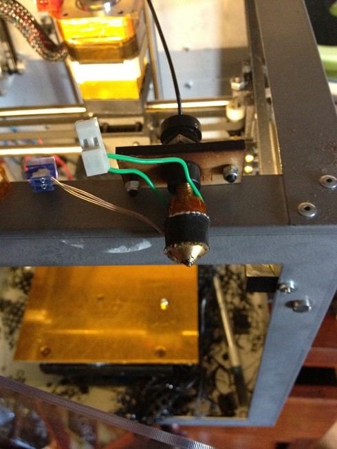
you should now have the hot end free from the extruder assembly.
remove the black rubber insulators, (these should slide right off)
find the bulge in the nozzle bolt under the kapton, this is the thermistor.
rotate the hot end away from the thermistor and it's wires and use the craft knife to cut a slit in the kapton, then peel off the kapton and remove the thermistor.
Now use the plumbers vice pipe grips to GENTLY grip the peek plastic, and the spanner to remove the nozzle.
if you find that the peek undoes, but the nozzle does not, then remove the peek, grip the brass pipe (CAREFULLY) and undo the hot end, then replace the peek.
After taking off the nozzle you should find that you can remove the heater element using your fingers.
In order to get to the wires you need to remove the clay that keeps the wires in place.
I used the pipe grips to gently squeeze the clay, this caused it to crumble.
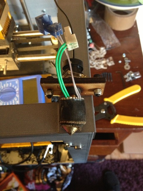
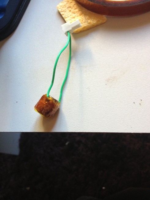
you'll be left with a threaded brass part, with furry wire wrapped around it, (the fur is the insulation)
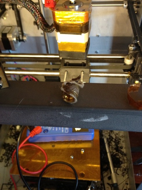
now check the resistance of the wire, not from where the wires from the plug attach, but the actual resistance of the wire:
you see that the wire is intact, and measures 6 Ohms.
The fact that the wire is intact is a pretty good thing, and led me to believe that the best course of action was to re-wrap the heater barrel.
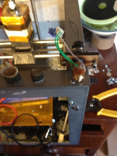
First, you'll see that the heater barrel is made of brass, (conductive) also that removing the clay has lead to a lot of that furry insulation material going AWOL. so wrap the barrel in Kapton.
then starting at the top, wrap the barrel round and round pushing the wire into the threads to hold them a set distance apart, after the first complete wrap, (well three wraps is what it takes to go top to bottom, add a layer of kapton tape.
then continue wrapping.
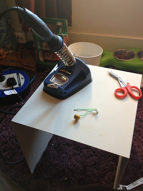
next solder the lead from your heater plug to the nichrome wire.
wrap the excess around the barrel and wrap in another layer of kapton tape.
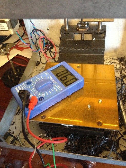
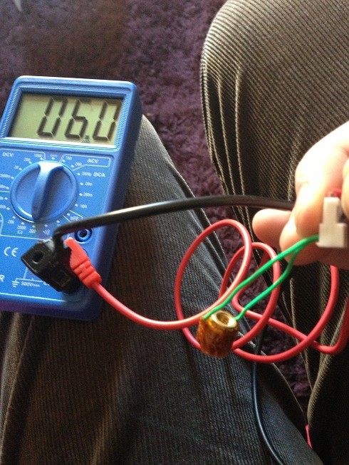
now, before you put it all back together, test the heater to make sure that you read the correct resistance:
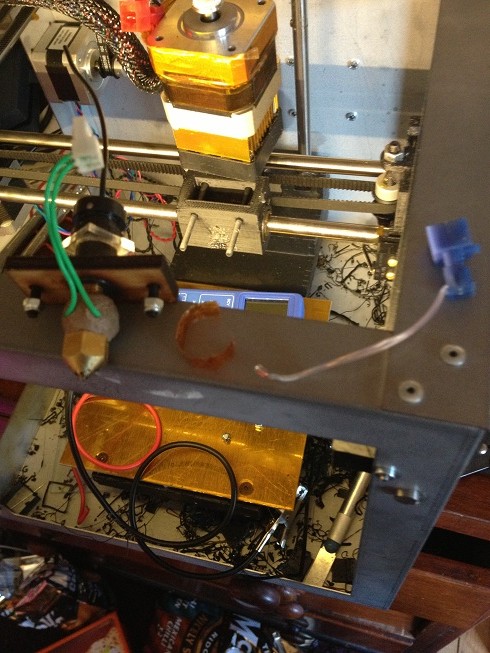
reassemble the heater/barrel/nozzle.
then tape the thermistor in place:
reattach the insulation:
and test:
unfortunately, when I tested, the hot end got to about 70 degrees and then the solder joint failed again.
I have a feeling this is because the nichrome is heating to 1400 degrees, and melting the solder connection, so to fix this, I've decided that the wire should be fixed mechanically as well as soldered.
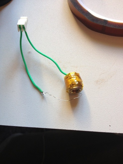
basically the end of the wire should cross over, then fold back and wrap around itself, forming two loops, (basically a variation of a linesman splice.) clearly using wire in wraps is going to reduce the length in the heater, and reduce the resistance, increase the power etc. so I decided that I needed to replace the whole thing
SO...
I had a length of AWG28 nichrome wire.
First, measure a 6ohm length of wire, (using a multimeter, unwind the wire and measure resistance along its length until it reads 6 Ohm.
then add a few cm for creating your wraps in the connection.
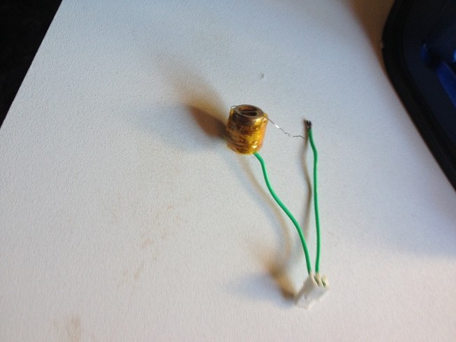
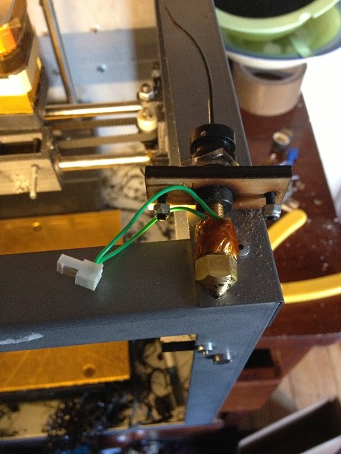
start by attaching the nichrome to the green heater connection wires. (splicing them with a loop and several wraps) then also solder.
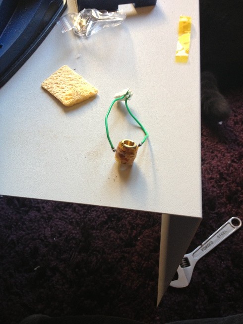
then wrap the wire around the barrel, until three wraps are complete, add a wrap of insulating kapton, and wrap with wire again, then kapton, then wire, and so on until you reach the end of the wire.
when you're done wrap in a few wraps of kapton.
test the resistance to see that it's 6ohms, then reassemble the hot end as above:

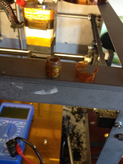
I've left the joint poking out the top so that there is a gap between the solder and the heater.
(the nichrome wire heats up well past the point where solder melts, so the simple soldered lap joint, that is actually inside the clay just simply isn't good enough to last the test of time.)
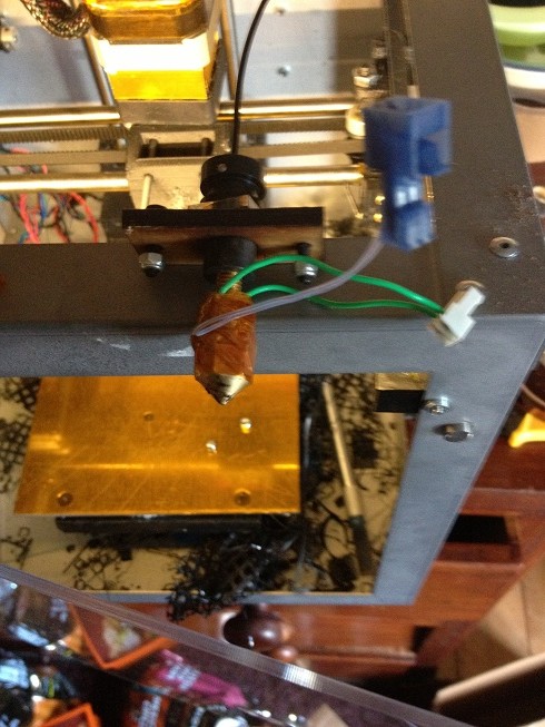
finally test.
when testing increase the heat in small increments.
looking at this:
V = 12 R = 6 (so I = 2)
http://www.wiretron.com/nicrdat.html
gauge is 31.
heat in the nichrome = 1400 degrees C, (solder melts around 200)
my replacement heater actually runs cooler. (a mere 900 degrees C)
but there is more wire, (more heating mass), there is less to heat, (no clay = less to heat) so the time to heat to temperature is actually a lot shorter than the time to heat the stock nozzle.