Showing posts with label make. Show all posts

Monday, May 20, 2013

Making an extension lead, (socket end)

So I dealt with mains electricity a couple of weeks ago.

Now this is a quick post on how to put together an extension lead.

At the end of the post on mains power I was pretty keen to stress that there were colour codes associated with mains power, well, as it happens the cable that I was able to buy for my 3phase extension lead does not conform to that colour scheme.

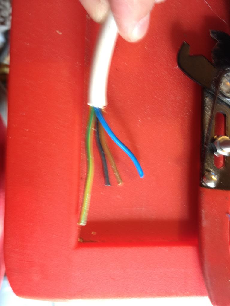
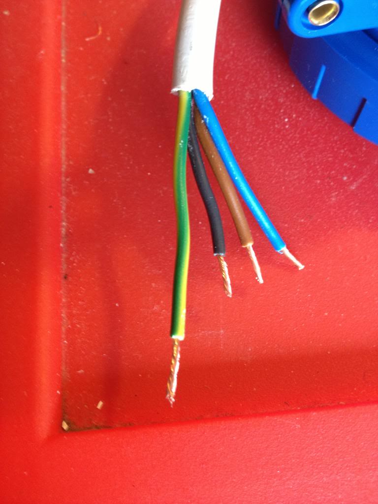
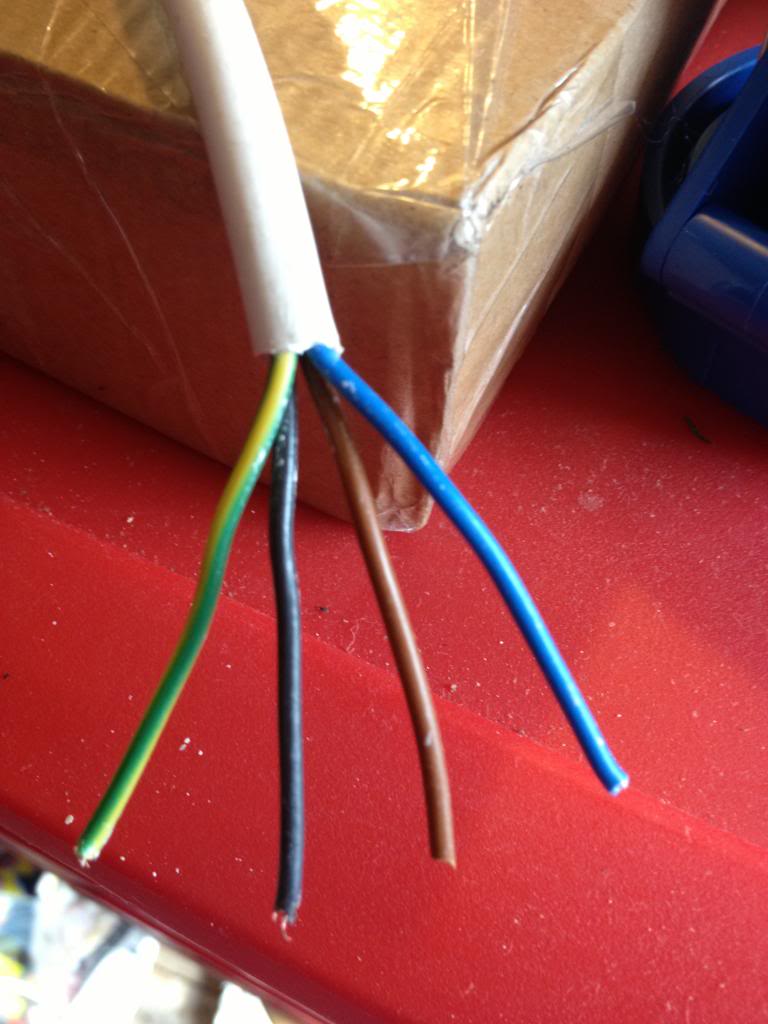
The cable has conductors that are Brown Blue and black with a green and yellow earth conductor.

So to start,
The cable I'm making will be a 16amp three phase 240 Volt cable.

 That means a 4 pin blue "commando" socket is needed. There are fairly uncommon in the UK (as our 3phase tends to have 415 volts. quite uncommon in the US (where the three phases are 120volts) but apparently is quite common in Sweeden. so you can get the plugs you want.

I found these plugs (and sockets) by searching Ebay for IP44, and IEC 60309.

You can find these at screw fix, (where they are £11 for each plug -I paid £1 each for five on eBay) sockets are also available at screw fix, but again I found them cheaper on line.
(screw fix is a nationwide UK distributor of all sorts of trade type building materials, it's open to the public, so if you can't wait for an item to ship they may be the best bet!

So I'm going to start with he socket end.

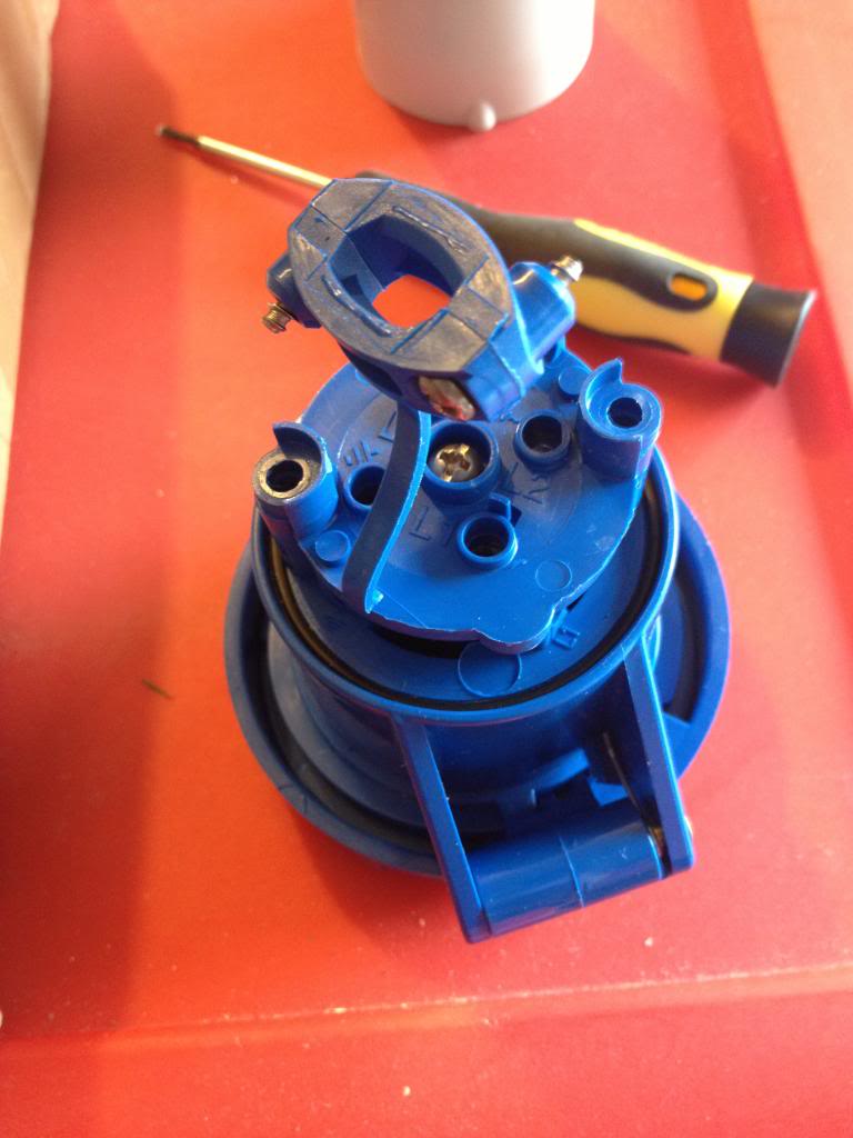
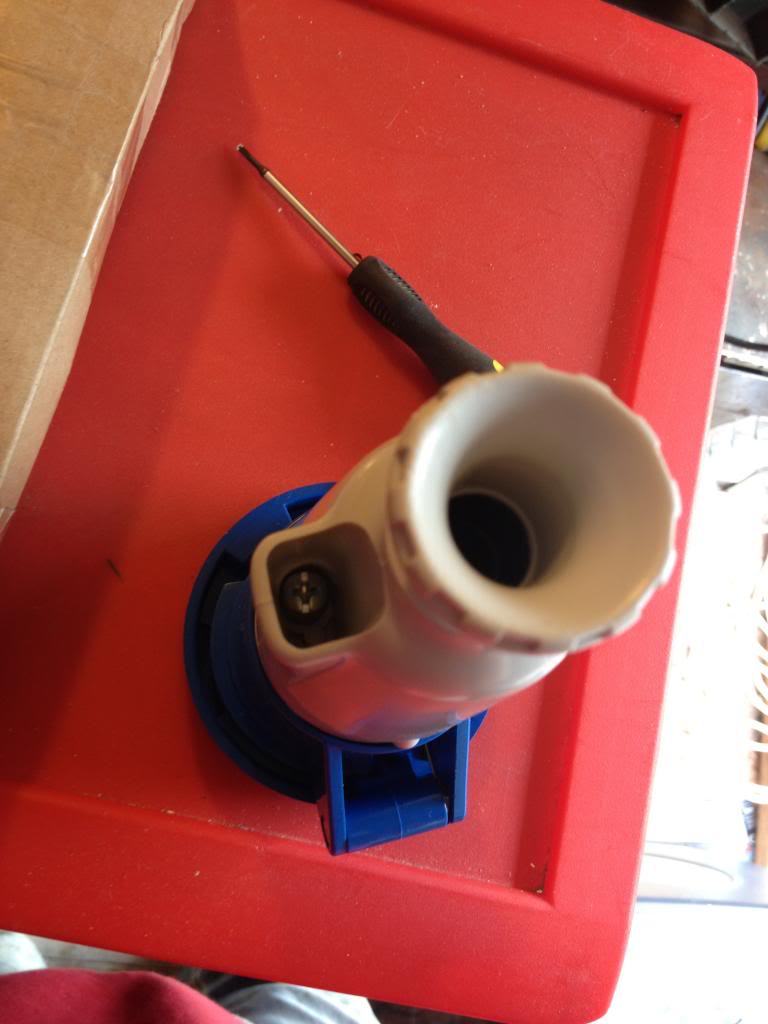
Take the socket apart such that the back cover is away from the connectors,slide the back cover over the wire (with the open side facing the bare end) so that you'll be ready to seal up your connector later!
To remove the back of the socket use the two cross head screws that are located inside the grip portions.

Now take your 4 core wire and removing some of the outer insulation.
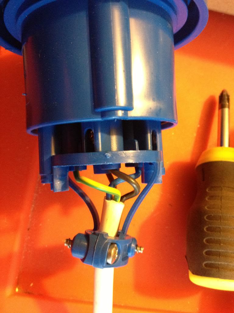
Then cut the phase leads to be shorter than the earth lead -the reason for doing this is that if the cable were ever put under strain and connections were to come out of the plug then the equipment you;re using would stay earthed, the worst scenario for electricity would be using a piece of equipment that was unearthed, that malfunctioned and became live, then you're the path to earth! By leaving the earth lead with some slack in to you're able to know that safety can be maintained, even if the cable has been put under such strain that conductors have started being pulled from connecting plug pins!


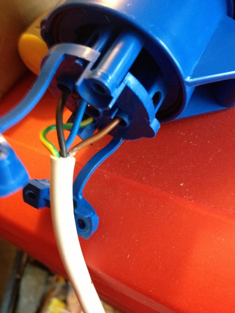
Now open up the cable clamp on the blue half of the connector and attach the wires into the holes indicated, with the brown black and blue wires being the phase wires and the green and yellow being the earth wires.


Then close up the cable clamp.


Now slide the back of the lead into place.


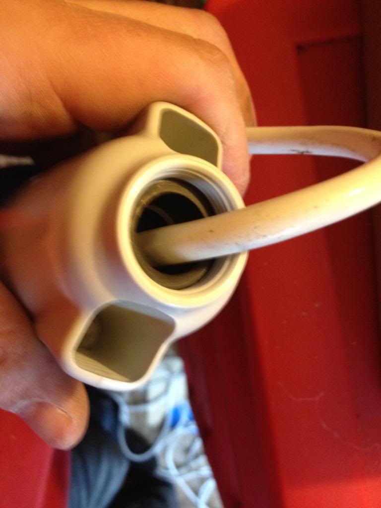
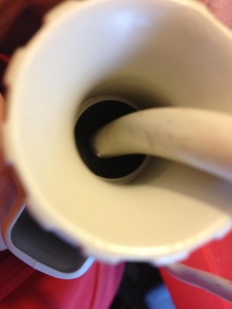
you can see a large black rubber washer, (it's about a half inch thick).

This is what seals the unit from weather (that and the little black o-ring on the other end)

Once you've gotten the back in place and screwed down, slide the final part of the back into place.

 this screws down squashing the rubber washer forcing it to grip the cable and provide a waterproof seal.

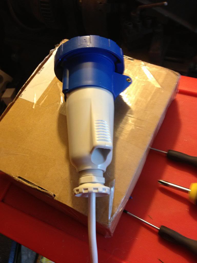
Finally, you have a lead with a socket on the end.


Monday, May 13, 2013

Mass production, tooling, strategies and budgeting.

This blog could be titled, How to get it wrong.

I'll start with the story, then I'll point out the failings.

A few weeks ago I made a new heater for my solidoodle 3d printer, I was quite happy with the results, despite having broken a drill bit in my heater block, I got around that, and I decided that was my fault, I clearly wasn't drilling the hole straight, it was a small drill bit, and they often break anyway...

When I bought the aluminium bar to make the hot end I had decided that I would probably want to make something else anyway, so I got a 2 meter length.

After making that first hot end I decided that I was going to make and sell a whole load.
I had enough aluminium bar, I had bought a hundred heaters at the start of the project, (knowing that I could sell the heater elements on their own!)

So I started cutting up that long bar of aluminium into 100 small pieces.
by about the 3rd piece I gave up and went to ebay and bought a small hobby band saw. -this worked great for cutting the aluminium, right up until the blade broke -though this had come with the saw, (which only cost £30), and had made 99 cuts, -failing on the last)

After this I got my set square and scribe and marked out where I needed to drill holes on all 100 blocks that I had cut. then I centre punched them. -this is time consuming, that was 600 holes that I marked!

After this was done I decided that I'd start drilling, rather than drilling by hand I decided that I'd use my fathers pillar drill, a Draper tool, I dutifully loaded the drill bit into the chuck, and set about drilling holes, I started by drilling 2.5mm hole through all of the holes I'd marked, a lot of the holes needed to be 2.5mm, others would benefit from a pilot hole being drilled anyway.

However I found that on the point where the hole for holing the thermistor met the hole for the screw securing the thermistor, the drill bit would catch and break. this was the same problem I'd had with the hand drill, but now I was getting this with a machine drill, one that was square, level and had no lateral forces, clearly there was a problem with the way that the cut was being made, swarf from the hole was catching and causing the bits to break at an alarming rate.

Eventually I managed to get a few holes drilled carefully that did meet, (afterwards I bought some 2.5mm end mills that I would use in the drill to make these holes meet more successfully!

At the end of the time I had set aside that day I had 11 pieces half made, I had the holes for the thermistor set-up drilled successfully, and the long hole through the block pilot drilled. at this point I'd been at it around two hours, and decided that was enough... -and besides the drill had gotten quite warm and I thought it could use a rest!

One morning the following week I decided that I'd continue my project. however within ten minutes of starting the drill the motor had caught fire.

In the end I took the pieces home and finished the first batch with a hand drill.

I tapped them and installed the heater elements.
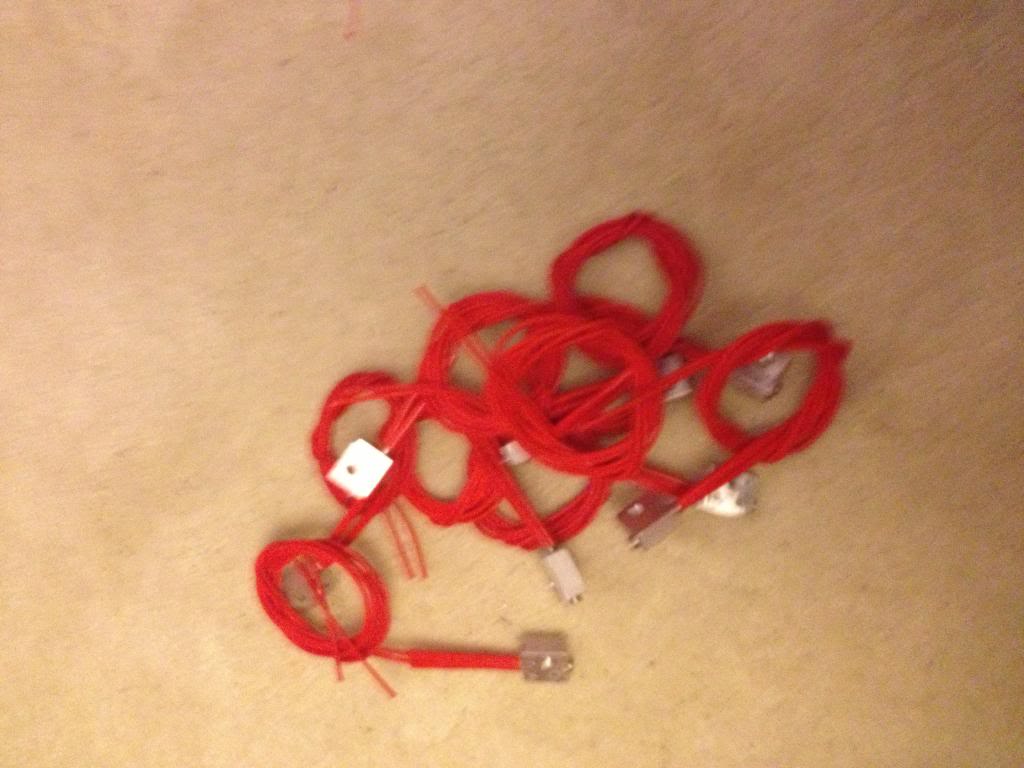
As it's a new month I've been paid and gotten some more money to spend on this project I've now ordered the thermistors, wire and heat shrink to finish these heaters up.


So... let's look at where I went wrong.
First, I'm hoping to sell these for around £12 - £14, this is in line with what others have sold for on Ebay.

the heaters were £130 + £15 import VAT for 100
Aluminium bar was £10
Thermistors are£70 for 100
heat shrink is £5 for the 6m of 1mm heat shrink I need
and £3 for the 5m of 3mm heat shrink I need.
wire is around £2 for 10 meters, (and I need 200meters) so £40
the grub screws cost around £15

So a quick sum up looks like I'm nearly £250 in the hole with materials.

Postage on each item is expected to be around £1. (so that's another £100)
Ebay will take ~£2 per item, (£200)
and pay pal will also want their 10% (£1.40 per item, times 100 = £140)

so that'll be around £700 of costs.
I'm hoping to sell these for a total of £1400

but here's where the problem starts....

now take roughly 25% of that away in taxation and national insurance that I'll need to declare. that's £175, leaving £525

Trying to do this cheaply has meant that I broke around £5 of drill bits whilst trying to make the blocks, and that £10 saw blade for the band saw.
(leaving £510)
I'd busted my dads pillar drill, because it's a hobby tool, not an industrial tool, it's meant to spend about 30 seconds being on, then have ten minutes to cool down, now spend nearly three hours in constant use, so that it over heats, and breaks down the insulation, (and then catches fire)
a complete replacement is around £300, second hand maybe £150, or a new motor will be around £100
My "profit" is now a pretty shabby £400...
then I spend a couple of hours cutting up the aluminium bar, a few more hours in front of the drill, a couple of hours sourcing materials, I'll conservatively spend probably 15 minutes per item with listing on ebay, talking to buyers, packaging and going to the post office to actually post the things.
(that's 1500 minutes, or about 30 more hours). I spend around an hour designing the thing in the first place.

Based on the initial ten I have that's 6 hours of machining and making,
So that 100 will be about 60 hours of machining, plus 30 hours of listing and posting.

So that £400 I've got remaining will need to pay for about 100 hours work. about 2/3rds minimum wage.

in other words.
I started out thinking, cool, the parts for this will make me loads of money, I'll spend about £2.50 on an item that I can sell for £14.

But,
using hobby tools has increased costs due to breakages.
Using hobby tools has meant that I can't work for more than an hour at a time without significant machine downtime to cool off, increasing the amount of time take to produce parts.
Funding this venture myself has meant that I've had to wait until pay day to get more funding. - I could have taken this to a kikstart project, but them I'd have 100 angry customers breathing down my neck saying that my lack of planning or prep wasn't their fault, and where is their money etc.


The long and the short of it is:
before you decide that you want to give up your day job and live the dream of running a tech startup. do your sums first. be realistic.
I was wishfully thinking that I might get around £700 for what would be an easy day stood at a band saw and a drill. -actually I was thinking I could use an ordinary hack saw to do this work!

What I though would be around £100 per hour I'll retired a millionaire next week, has actually resulted in being a drain on time and resources. Maybe with a few thousand pounds of investment for industrial tooling I'd do better -but I doubt that also!
Monday, March 18, 2013

Breakout board for the Raspberry Pi


I've been talking a lot about my Raspberry Pi recently. That's because I've been playing with it a lot!
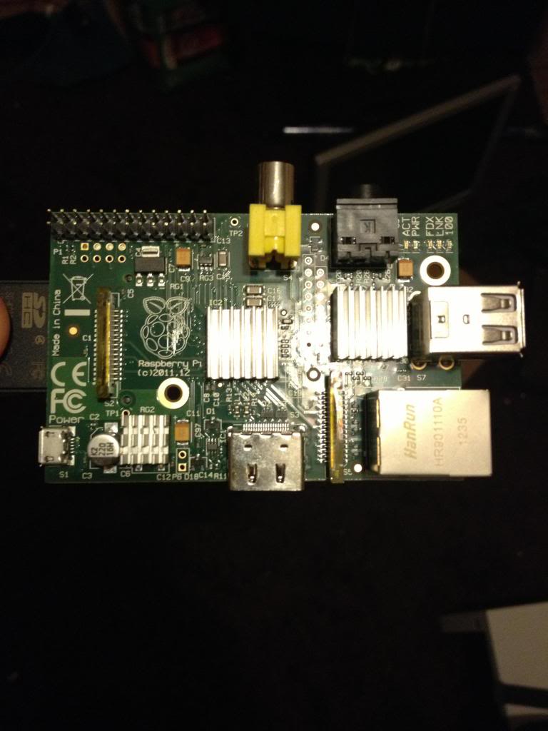
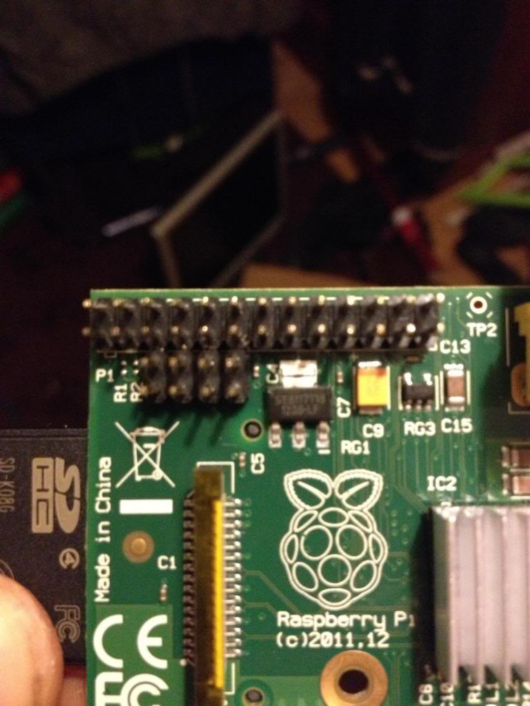
On the Raspberry Pi there is a row of pins called GPIO pins, the block of pins is called P1.
These are on most versions of the Raspberry pi the only  input/output pins available.

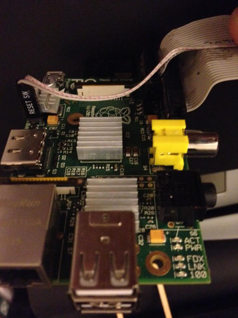
However on later versions there is a set of 8 pins next to P1 that have no pins soldered in.


So the first thing to do is remove the solder from this header (P5).

The plug for this header is supposed to be mounted with pins facing downwards. personally I don't understand why I'd want to have cables trailing from the top and the bottom of the boards, to me this seems like a crazy idea. I'd much rather have all my pins accessible from the top. especially when I use the mounting holes in this rev 2 board to screw the board down!

After removing the solder I've added 8 new pins to P5


Next there is a new pin header called P6 on the board, this is a set of pins that a reset switch can be attached to.


So now I need to get a plug to attach to these pins.

I started with a 44pin IDE cable.

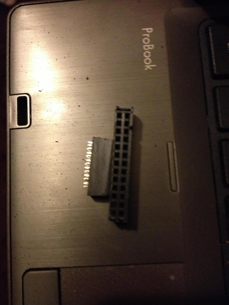
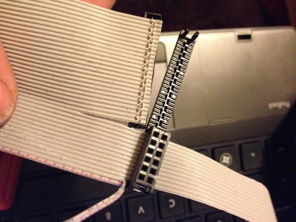
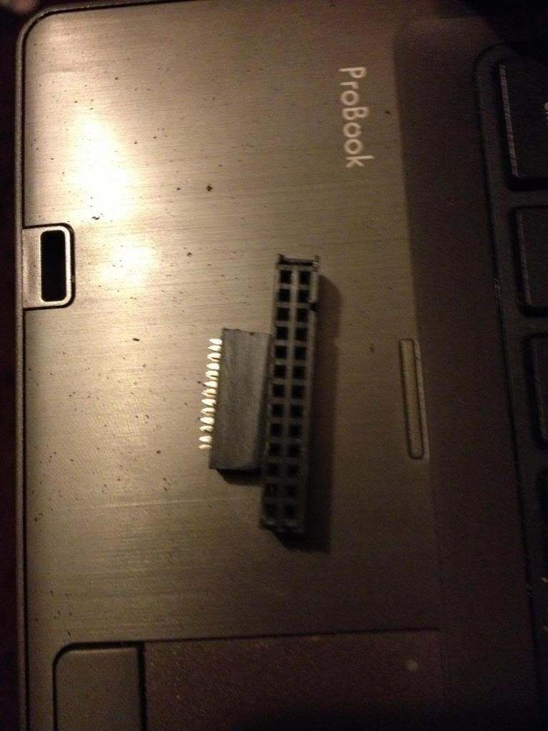
Start by removing the cable from the connector at one end, put that connector that you removed into connector P1. mark the first un-used set of holes, then using a utility knife cut through this set of holes.
This wastes 2 pins in the connector, but don't worry.


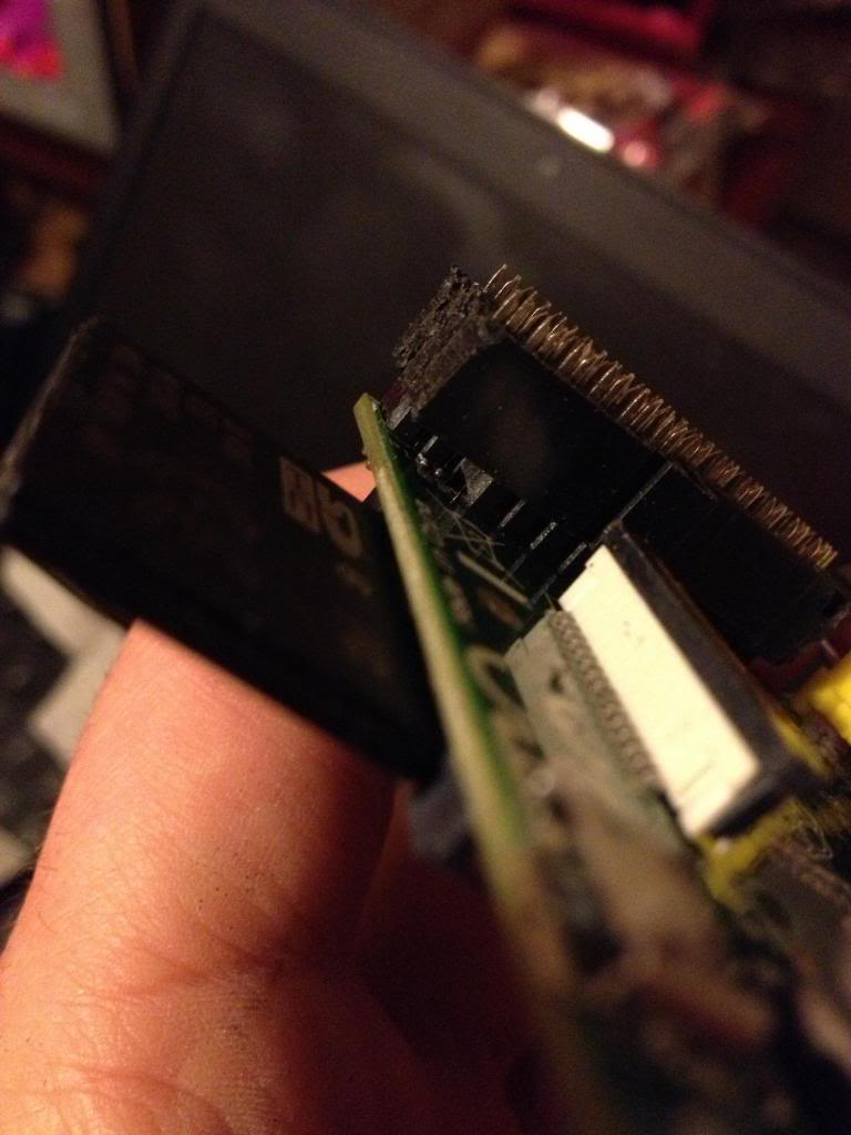
Now using a file or some sand paper you need to sand down the sides of the connector plug so that you can put these two plugs next to each other on the pins of P1 and P5 without them bending the pins.
This is halfway through,


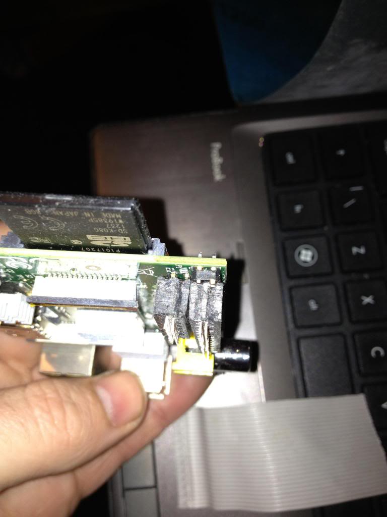
In the end the plugs should comfortably sit next to each other.

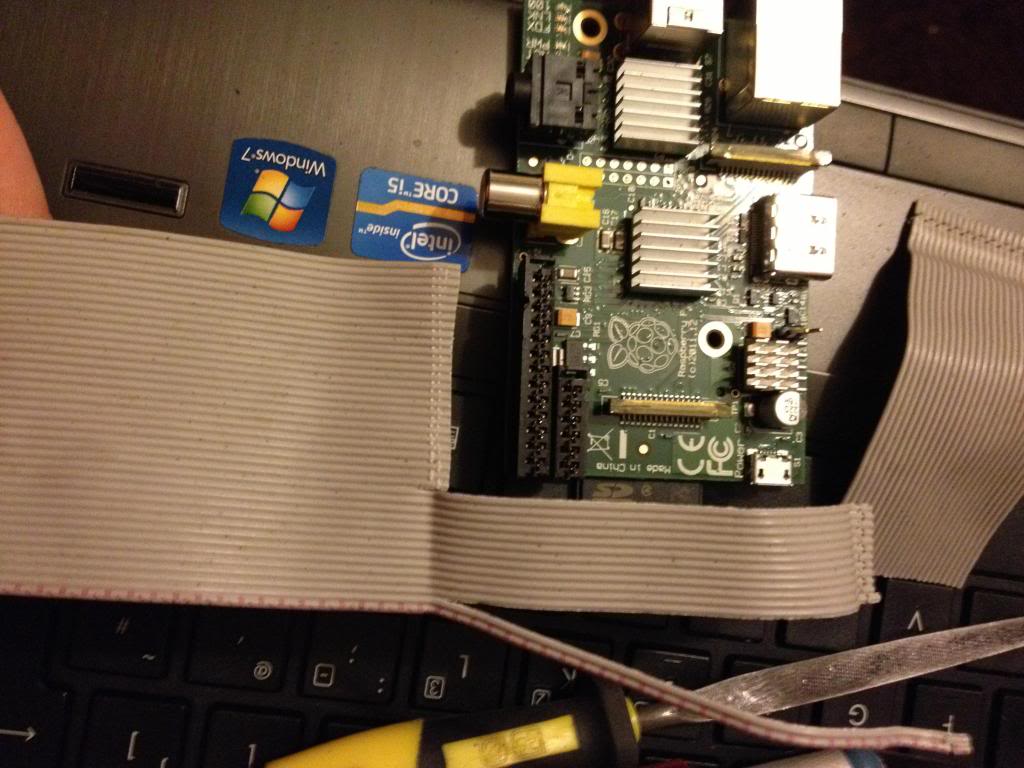
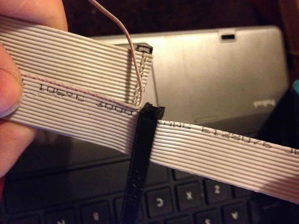
Next take the cable, and divide it to split the cable with 26 pins from end of the cable, lay this across the board and trim the first 26 conductors in the cable so that they are about 1 and a half to two board widths shorter than the rest of the cable, also split the first two conductors away from the bulk of the cable.


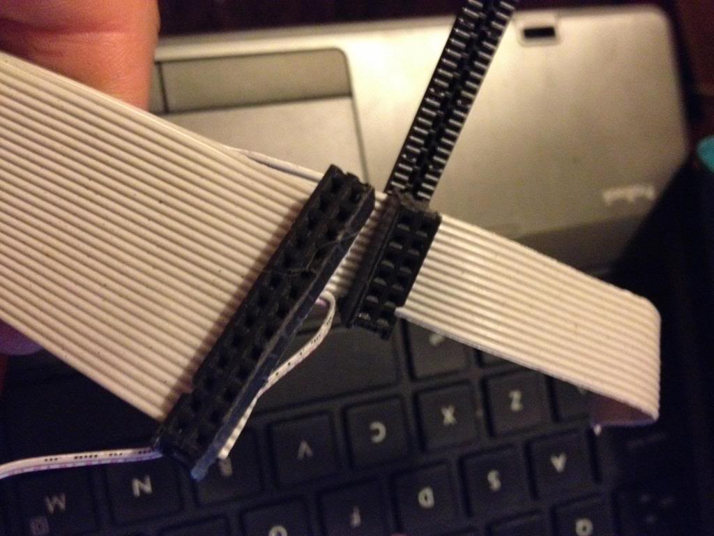
Now attach the larger half of the connector that was cut in two to the first 26 pins.


Next turn the cable over, and attach the smaller half of the connector to the remaining part of the ribbon cable, so that it sits diagonally next to the P1 connector.

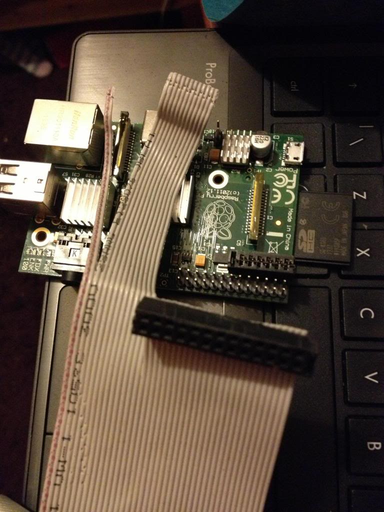
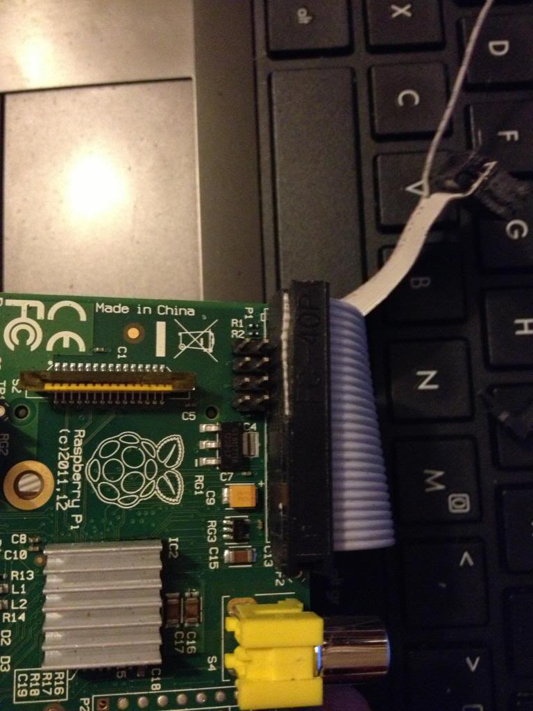
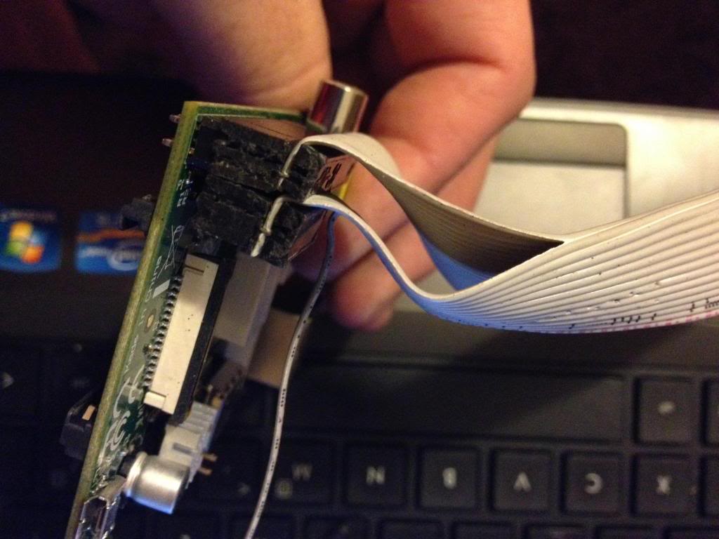
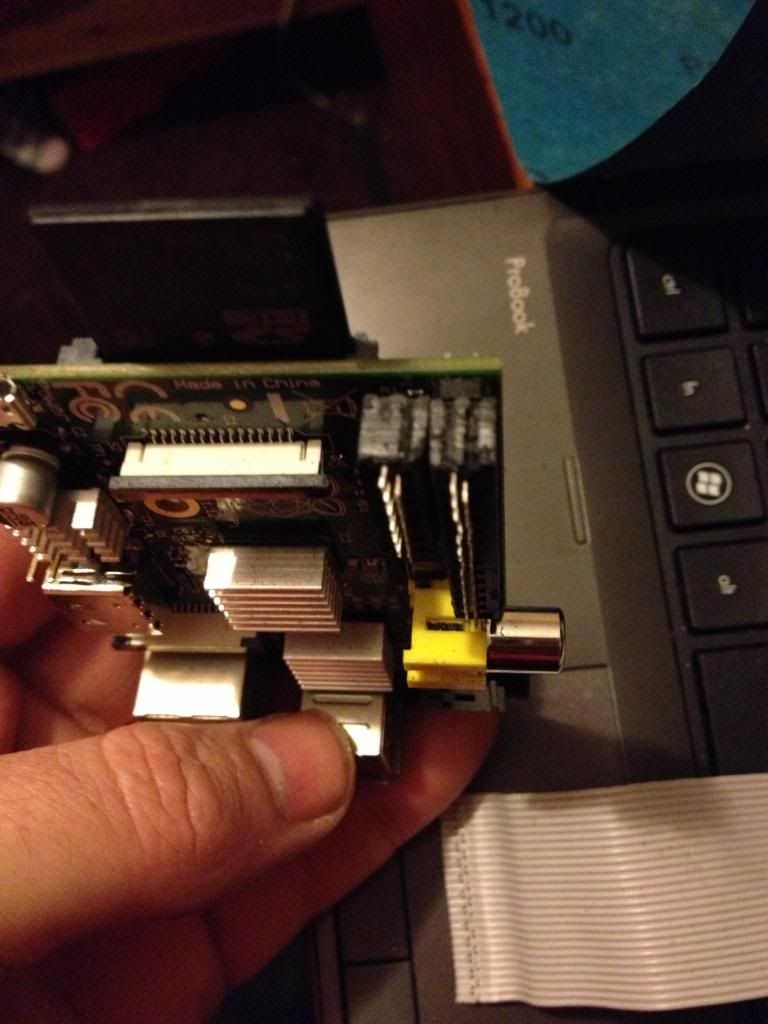
When you fold the cable over, the two plugs should sit next to each other in such a way that they will easily connect to the P1 and P5 headers, (obviously the sides of the connecttor previously sanded away to allow this fit must now face each other!)


Next cut the cap for the plug and glue over the top of the cable to insulate the terminals that have cut through the insulation on the ribbon cable.

And ensure that both connectors can be attached at the same time.

Finally attach a connector to the remaining two conductors in the cable and attach this to P6. I salvaged the connector from an old computer case to it says reset switch, shorting the pins of P6 resets the device so it is apt to use this connector.

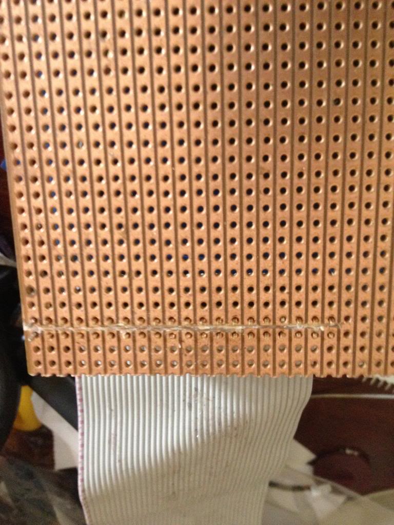
Next using some perf board cut the copper track on 22 rows ready to solder the 44 pin header.

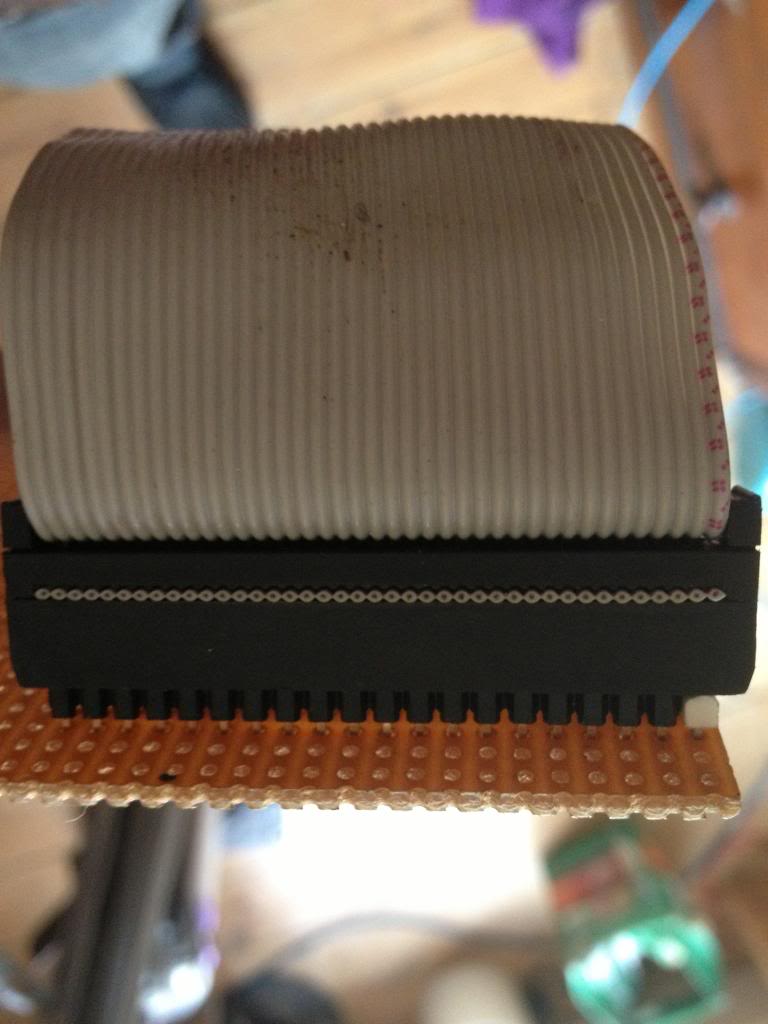
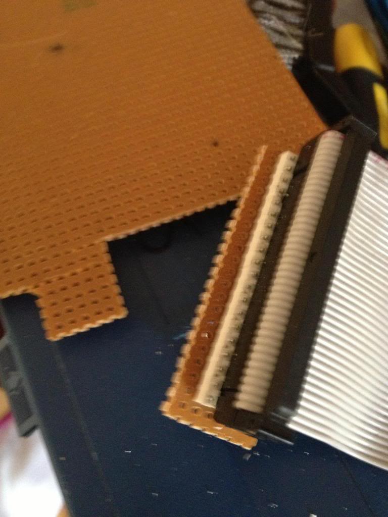
Now solder in the header pins to the perf board.
I've used a 42 pin connector which is black, and used a 2 pin white connector to mark pin 1.

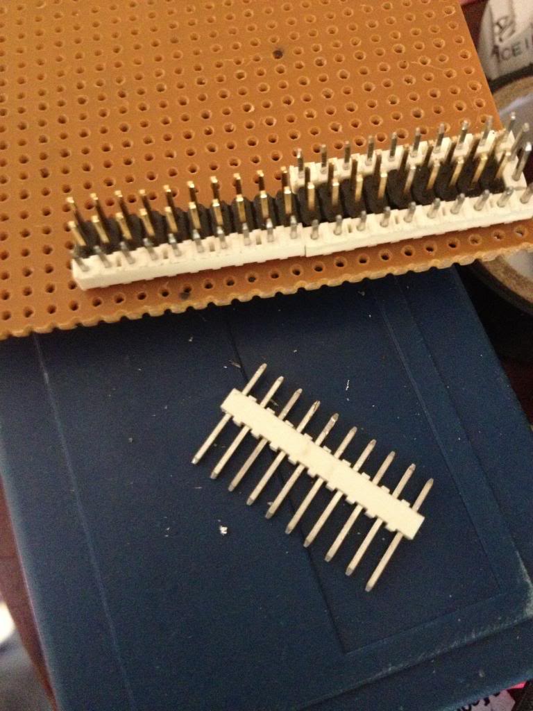
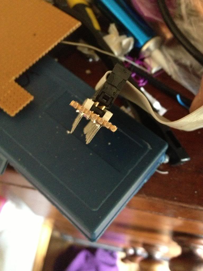
After soldering the cable header pins to the perf board you need to solder some pins that will go into the breadboard.

I used single rows of header pins next to the black connector header.


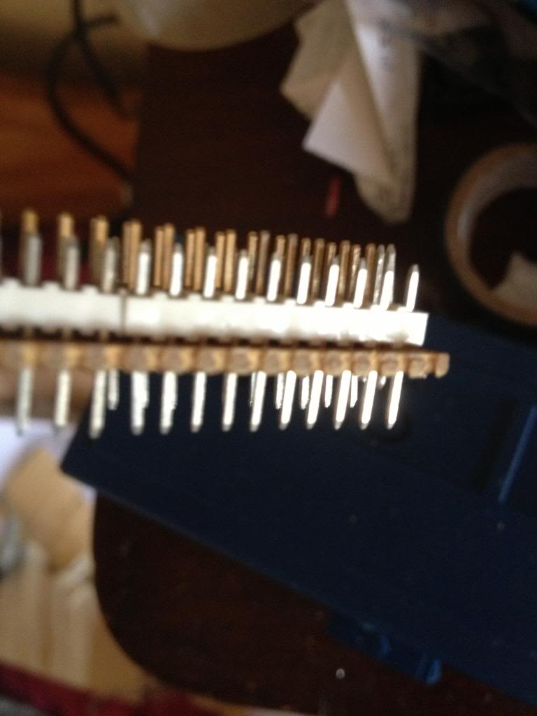
with the pins pushed down into the white block so that they protrude farther out the bottom of the perf board.


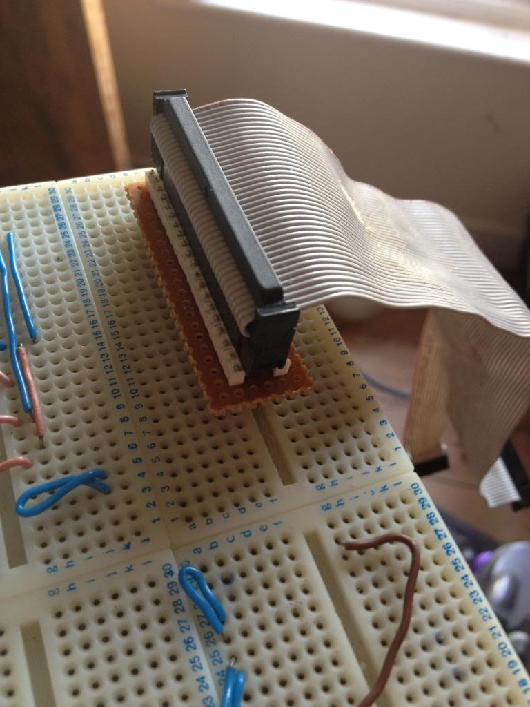
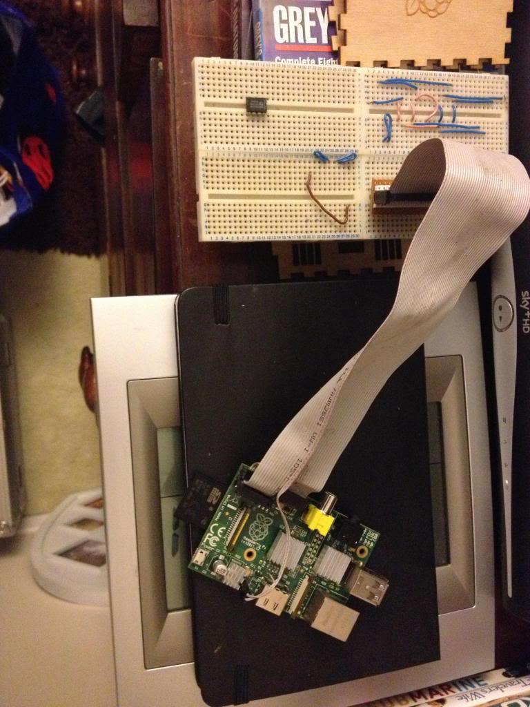
Finally the raspberry pi can be connected to my breadboard.


Monday, December 31, 2012

Making door signs with a 3d printer.

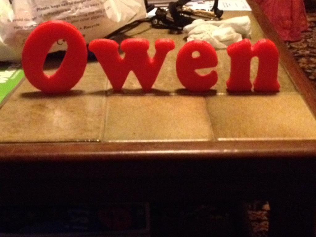
This was a little bit of fun to give my nephew something nice for Christmas. I thought that it might be nice if he got a nice sign for his bedroom door with his name on it.

Rather than go out to the garage and get busy with the jigsaw/sandpaper and paint like I once would have I decided that I'd have a go at printing some letters that could be stuck to a door.

So this is a step by step guide on how to create letters and a door sign, from design to creation.

Modeling
First you're going to need 3d modelling software, this blog post will explain how to use the Creo elements software since that's pretty good and free.

Open the package, as before you see your work plane and nothing else,
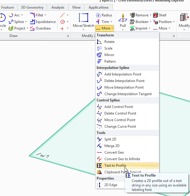
in the 2d toolbox click on the more button, and then select "text to profile" tool.

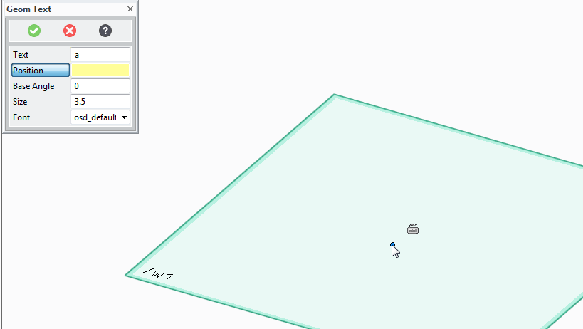
A box will now appear where you can enter the letters that you want to print.


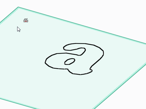
As an example I've put the letter a
Now you press the position button and select where in the work plane you want the letters to appear.
(click somewhere in the middle)

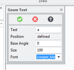
Now you need to define the angle that the letters will be at (zero is probably fine!) the size, -I want them large for sign so I choose 100, and the font.

I've chosen cooper black as the font. it's not the worlds fanciest font, but it is pretty good for printing, there are no weird angles etc no parts that will end up impossibly thin or unprintable.

Once the letter is on the page we're going to need to give it some depth.

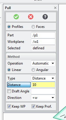
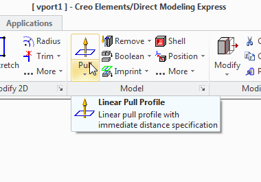
So use the pull tool:


And select the pull width to decide how fat you want the letters to be:


Now delete the work plane ans select save.

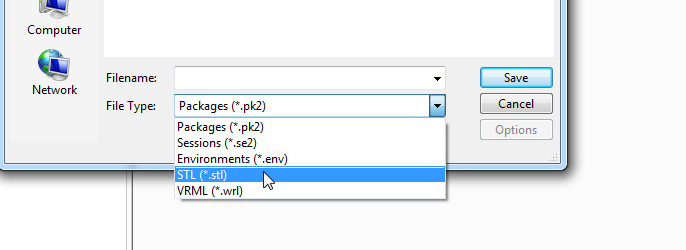
change the file type to STL


Now select to save All Objects using the button at the top, (that's only part 1)


type a file name and press save.

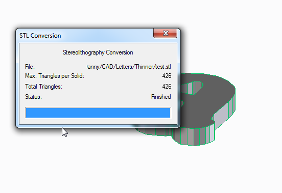
You can close the STL conversion box that appears.

Slicing
Now launch pronterface by running the pronterface.py file

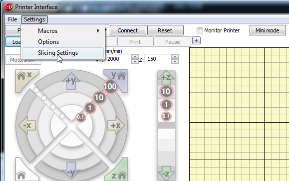
you now need to access the model slicer.
select settings, slicing settings

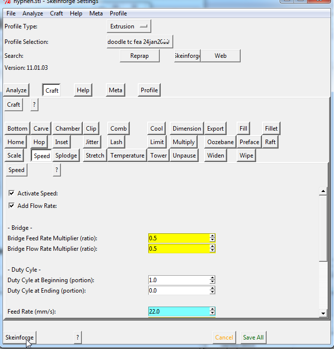
This opens a new window called skeinforge,
click on the skeinforge button at the bottom to open your model

Select your STL file and press open.

Now Wait...
...

...

Two new windows will appear, these describe in a colourful way how the models will be built. you can close these windows now.


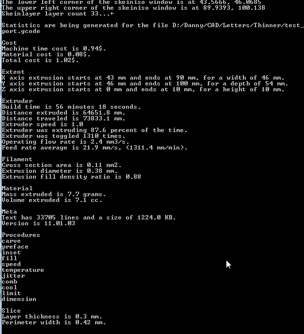
Now if you look at the python command line window that is open you can find some interesting things about your print that's going to happen, (like how much material will be used, how long it might take to print etc.

Printing

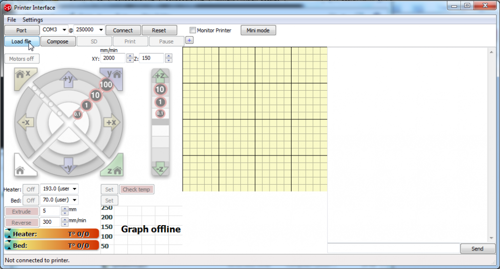
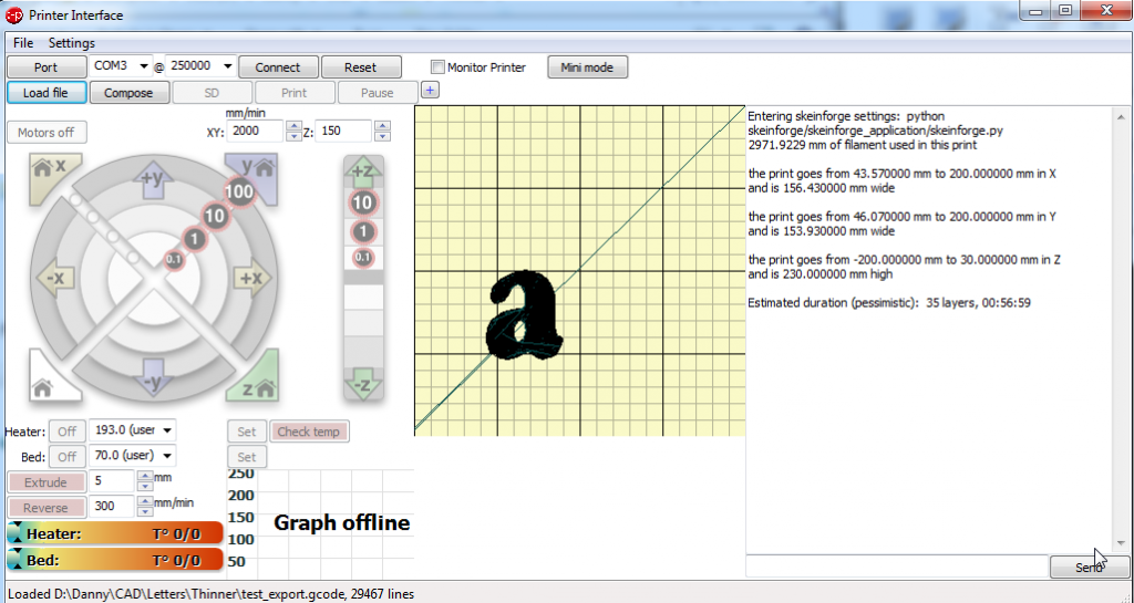
Now you should be looking at the pronterface screen again, select load file and open your file:

You now get a picture showing you how your file will look and where it will be printed on the bed.

Make sure that you have the correct com port set, and press connect.
Check the box that says monitor printer (in-between reset and mini mode)
now press set on the bed temperature.
watch as the actual temperature line ramps up to meet the target line.

When the bed has heated up, click set on the heater button, watch as the nozzle comes up to temperature.

When both the bed and the nozzle are at printing temperature then press the print button, then watch your printer make the letters for the door sign.