Recently you could be forgiven for thinking that this had changed from the idiots guide to puttin' shit together, to the opinionated guide to how you should have done your projects, or the idiots musings and bad teachings.
I'm definitely going to continue the tutorials because it's actually quite fun to write them, and I'm finding that as I go over the ground again, I'm re-remembering some stuff that I'd completely forgotten about. But this post is right back to the core of why I even started this blog, and that's to share something that I've made.
Firstly,
There's your warning, but if you can't figure out for yourself that there is an element in danger in modifying anything that plugs directly into the wall then you should probably stop reading now and go elsewhere.
Theory
The theory for this is so simple, I have a power supply (a computer power supply), and I want to turn it into a bench power supply, so I pretty much just need to cut off the wires that aren't needed, and attach the appropriate plugs to the wires that are need!
How it works
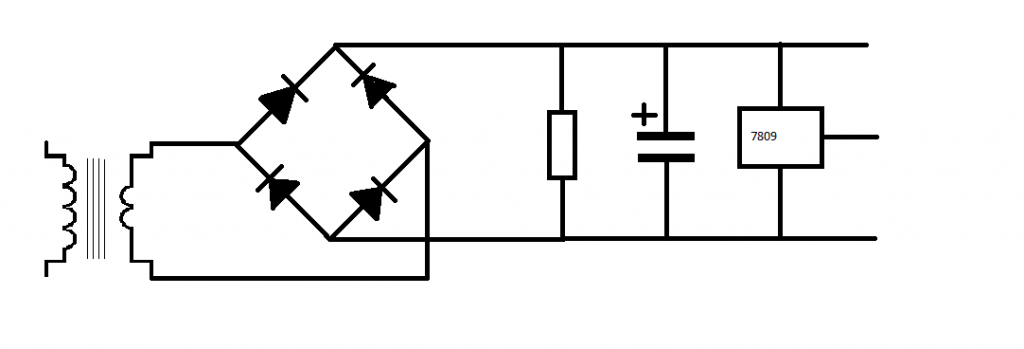
The computer power supply maker has done all the hard design parts for me it's a switch mode power supply, mains supply and as it's switching faster, the transmission of the energy inside the ferrite core, basically that means that inside the power supply is switching on and off at a very high frequency, this is much faster than your 50Hz s of the transformers inside is more efficient, more efficient means that you're not generating as much heat, and not as much energy is wasted as heat.
A traditional power supply, would require an absolutely huge iron core surrounded by pounds of wire to be able to get the same kind of output power that a switch mode power supply (SMPS) gets.
Why it's important
The high frequency is important as that's what allows the supply to be so efficient. The fact that someone else made it is important because it means that you can make this supply inside a single afternoon.
If I was designing my own SMPS, I'd probably need to research for at least days, if not weeks, I'd need to source components. Create circuits to sense the output voltage and adjust the input if necessary, it'd be a lot of work, yet I can turn an old supply from a broken PC into a perfectly reasonable bench supply in a matter of hours.
Simple experiment
Before even breaking out the screw drivers, or plug in the soldering iron. I took a look at the computer power supply unit.
There is a big plug with either 20, or 24 pins on it. inside all these pins there will be a single green wire, with a black wire either side of it.
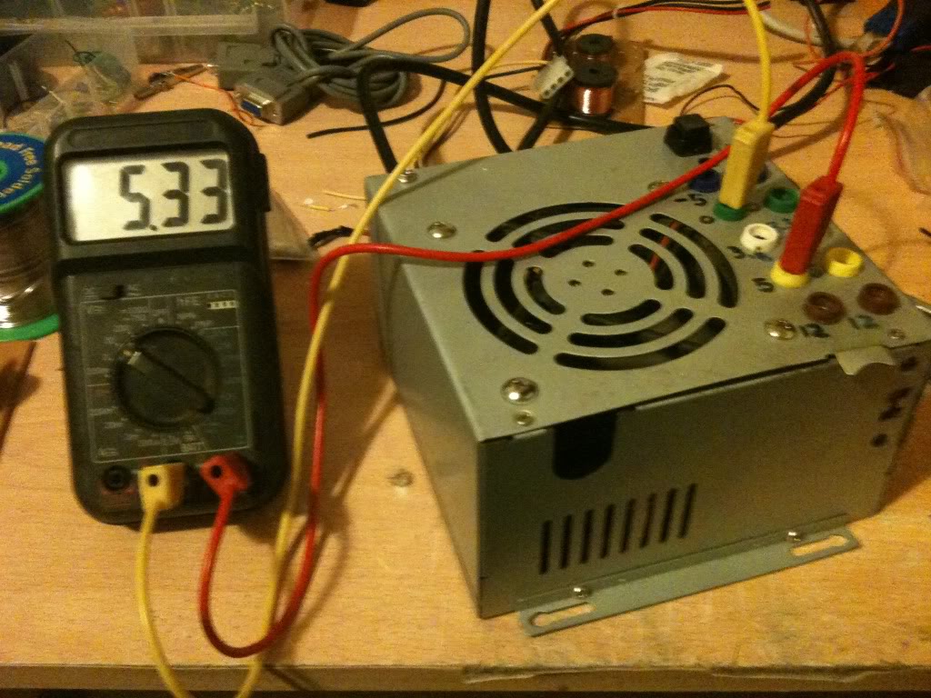
Using a small bit of wire I pushed it into the pin connected to the green pin, and one of the black pins from either side. The fans spun into life, and voltage could be measured at other pins.
You can just use the supply like this with no further modification, inserting your bit of wire to turn it on, removing your bit of wire to turn it off.
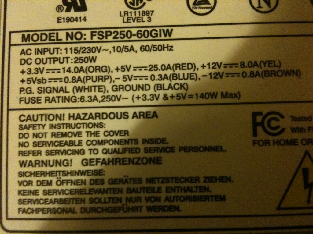
On the side of the case there was a table that telling me what colour wire carries what voltage, and what the limits of the current capabilities are for each voltage. this made it a whole load easier that searching for a pin out on-line for the ATX plug to know what pin was what.
Converting a power supply
Parts and tools required
>an old computer power supply
>a screw driver
>some terminal posts
>Wire cutters
>A switch (push to make locking switch)
>A LED
>A 10mm drill bit
>A drill
>A 6mmDrill bit
>Insulated screw terminals -these are not important, you may chose to leave these out
>A 470Ohm resistor
>A soldering Iron
>Solder (flux core)
Taking it all apart
The first thing that I did was take off the lid of the box, The fan is connected directly to the board with no plug to remove it, so I removed the fan from the case lid.
Modifying the part
Lets deal with the lid first,
I knew that in the lid i'd need to put a switch (basically in place of the wire that I had before),
You might want (I did) a nice LED to tell you that the supply is on.
I also wanted to put plugs that to connect the wires to in the lid.
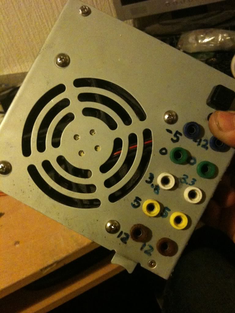
I chose to mount my plugs in two columns, (2 x 12v, 2x 5v, 2x3.3v and 2x0v) as these are the voltages that I'll use the most often, then I have one plug for -5 and -12, as I'll use these less often.
As it happens, banana plugs are usually stackable, so you won't really loose an functionality just using a single row of connectors.
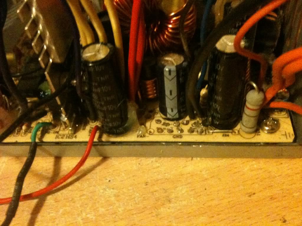
When I looked on the inside, of the power supply, I saw that there were basically two sides, one side has big heat sinks in it, and the mains plugs next to it, the other side is fairly low profile leaving the top of the case empty. I decided that I'd like to keep my plugs away from the side with exposed mains connectors that the bottom of the terminals might hit, and away from the heat sinks for the same reason
I marked out the lid and drill the holes for all the part to go into.
Then installed the plugs, LED and switch (I used a simple black collar for the LED it's called a panel mount and costs about a penny. -you could leave the LED out completely).
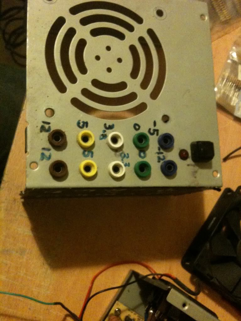
I just used a marker pen to write the voltages on the top of my supply, you might use nothing relying on the colour of the plugs to tell you the supply voltage, perhaps you might like to try etching or engraving, or using a label printer, I don't really care, pen works for me, and that's good enough.
Next as I have two plugs for one voltage, I connected these plugs, using a piece of wire running between them.
I also want to add a 470Ohm resistor to one leg of the LED (this is to limit the current that goes into the resistor).
(That'll connect to the 5v rail 5/470 = 0.01A or 10mA, enough to make the LED glow, you might like a bigger or smaller resistor depending on the needs of your LED, it's also 1/20th of a watt, so a simple small 1/8th watt resistor will be fine.)
I soldered leads to everything ready to connect to the terminal block connector.
Finally I was able to stop working on the lid and move onto modifying the actual PSU.
One thing that you'll notice is that the wires are colour coded depending on their job. And there are a LOT of wires that are the same colour, in the supply I used there were about 10 black wires, all 0v, all from the same pad on the PCB!
I needed 3 black wires, could have got away with 1, but three was good (one for the power button, 1 for the LED and 1 for the output plug).
I really only needed 1 -12 wire, only 1 -5 wire, only 1 +12 wire. and two +5v wires (one for the plug, and one for the LED.
You do only need 1 3.3v wires, but in addition to the thicker wires you must keep the very thin orange wire, this is the sense wire that determines what voltage is being generated, and regulates the supply, without this wire your supply can float.
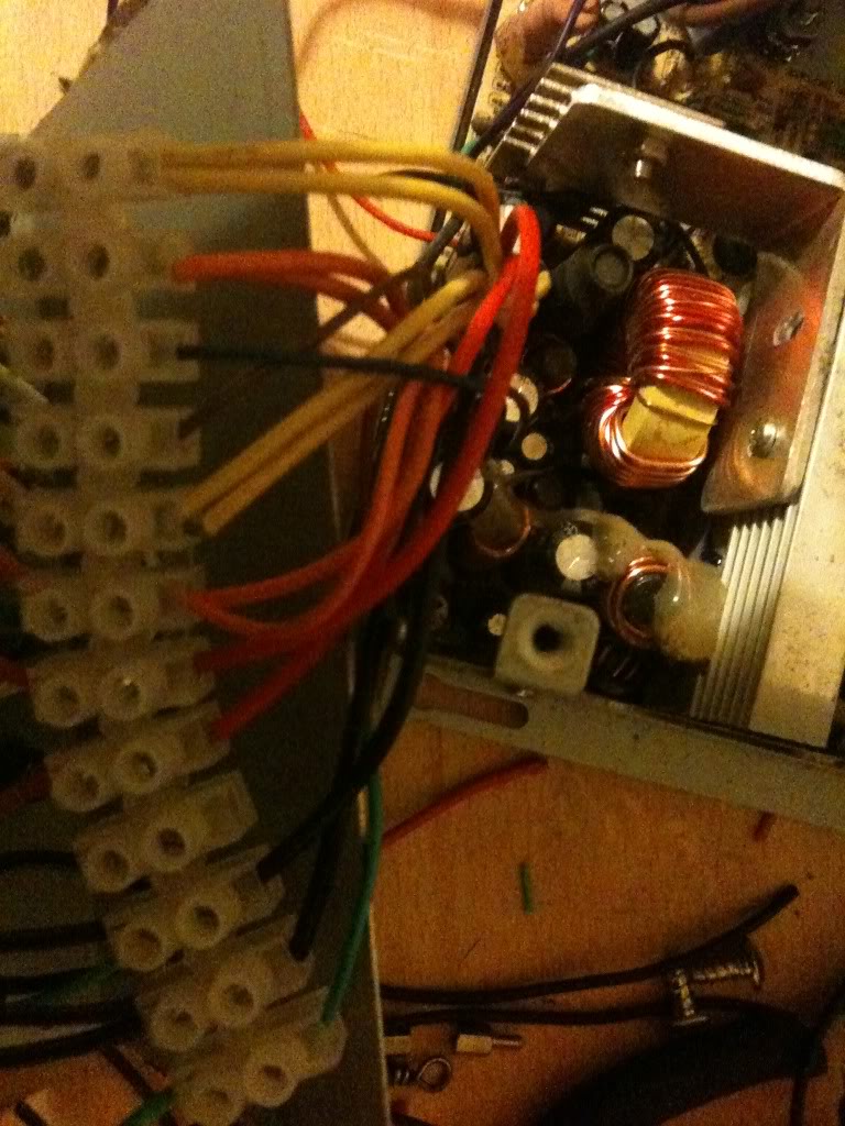
Anyway, I cut away the wires that I didn't need (that I could get to)
I couldn't get to cut the red or yellow wires, so I'm going to tie these off later in some spare terminals on the connector.
Putting is all together
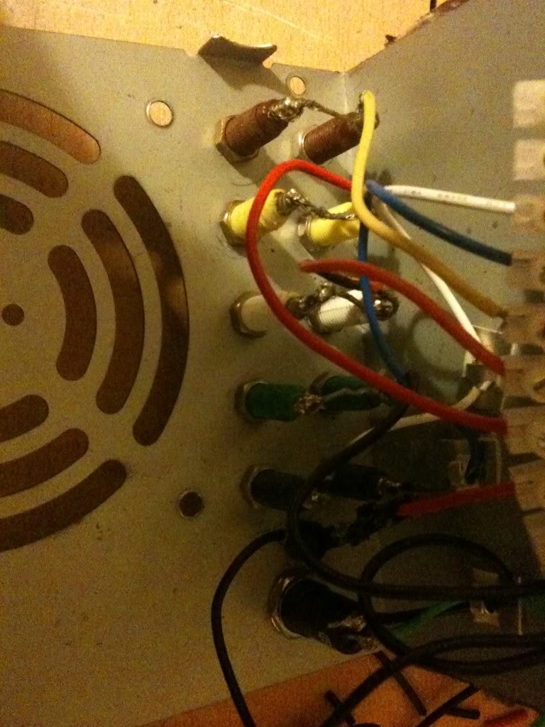
So I'm now in a position where I've thinned out all the wires that I don't need, and I've trimmed all the wires that I do need to about four or five inches long so that I have plenty to work with.
Now I striped back the wires, and attached them to the terminal block.
It doesn't matter what order you make the connections in, just that black wires connect to ground, terminals, and the negative side of your LED, also that there is a black wire attached to one terminal of your switch.
You want the green wire to attach to the other leg of your switch, and a red wire to attach to the LED for your "on indicator".
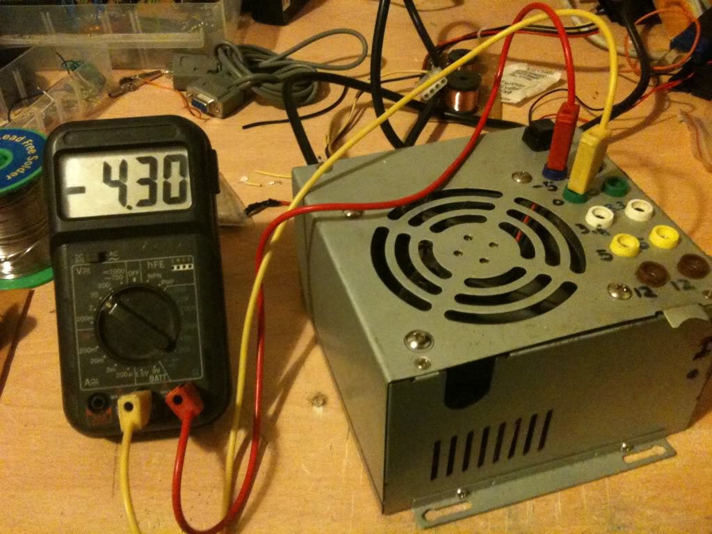
Yellow wires are alwyas 12v, Orange is always 3.3v, Red is always 5v, minus five and minus 12 however do not appear to have a set colour scheme, and as such may vary.
The colours were written on the outside of the supply I used, you may have to poke around with a multimeter. or look for an ATX pinout and just select the correct wire from the plug.
Once all the wires were connected I attached the fan to the top of the case again, and put the top of the case onto the bottom. as I said earlier, make sure that the bottom of your sockets do not touch the metal bits inside. Also make sure that no wires are touching the heat sink where the insulation could melt, and that no wires or the large terminal block is getting in the way of the fan.
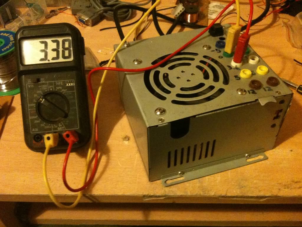
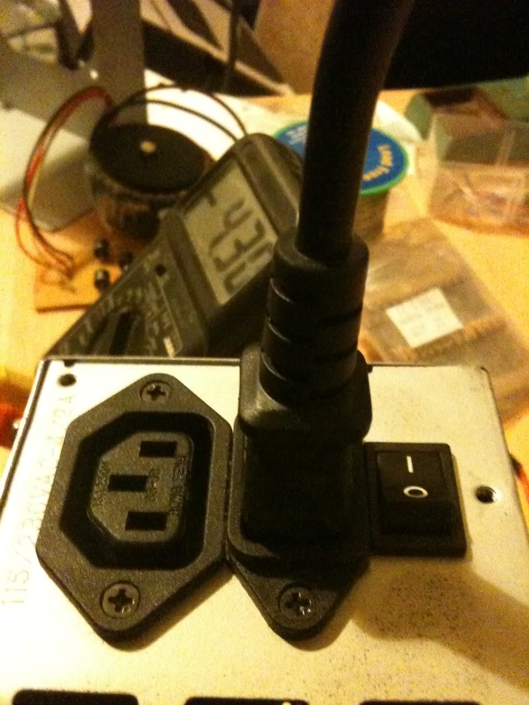
Now I measured The output voltages using a multimeter.
Since I'm always seeming to run out of power outlets, I chose a power supply that lets me get mains power out as well so I can daisy chain equipment together.
CostsThis is not the cheapest project in the world, but it is cheaper than buying a power supply with the same amount of usable outputs, regardless of whether those outputs are of a fixed voltage, or five variable voltages. I had everything either in my parts box/junk bin so this really cost me nothing.
There are 10 4mm sockets, these are 20 pence each from Rapid Electronics
http://www.rapidonline.com/Cables-Connectors/Connectors-Single-Pole/4mm-Connectors/4mm-Sockets/63893
(total cost £2)
The Square Single pole single throw switch cost 36 pence.
http://www.rapidonline.com/Electronic-Components/Switches/Push-Button-Switches/Square-push-switches-1A/30275
(toal cost £2.36)
LEDs cost around 9 pence (or less) (when you buy them in bulk).
here's one for 6 pence http://www.rapidonline.com/Electronic-Components/Optoelectronics/5mm-LEDs/Low-current-5mm-LEDs/29336
(total cost £2.45)
Resistors cost even less than this when bought in quantity.
http://www.rapidonline.com/Electronic-Components/Resistors-Potentiometer/Carbon-Film-Resistors/CR12-0.125W-Carbon-film-resistors/65192
65 pence for 100, seriesly people stop shopping at Maplin/Radioshack
Rapid cost 65 pence for 100, (or ~ half a penny per resistor).
Maplin cost 25pence per single resistor. (50 times more expensive).
http://www.maplin.co.uk/components/resistors/metal-film
If your project requires 3 resistors, it's cheaper to order on-line and have 97 spare/left over!
(total cost £3.10)
Now comes the expensive part, if you don't have a spare power supply laying about, (and don't have the resourcefulness to find one for free), then you'll have to buy one. for the princely sum of £7.86!
http://www.ebuyer.com/product/20083
Total cost £10.96! Much cheaper than any other power supply that I know of. in fact we're really knocking on the cost of a single voltage wallwart cost here, which has a lower power capacity and only 1 voltage output (which may or may not be adjustable!)
Alternatives, -and Why I didn't use themThis is something I started when I wrote up
the red light torch, there are so many ways to crack an egg. So my way is not the only way, just the way that I chose on that day.
Spring terminals:Spring terminals are useful if you're doing a lot of breadboard work, without a breadboard that has power terminals, but practically everything I've got is set-up for 4mm banana plugs, my multimeter, the power terminals on my breadboards, crocodile clips connect to 4mm plugs. Spring terminals may well have been cheaper, and indeed wouldn't require me to buy 4mm plugs to go with them, but since I'm set-up for using 4mm plugs it makes sense to use them
Binding posts:Yes, these are just like 4mm sockets, except that you can also attach bare wires and screw them down, making them a whole heap more versatile. The only reason that I didn't use these is that I didn't have any in my parts box, and I did this project one evening after the shops were closed.
Directly soldering the leads:I could have missed out the terminal block connector, and indeed the first time I made this supply I did. without that chunky connector however there are two things.
The wires that you can't cut off at the board end up loose in the case, you can wrap them in tape, but it's a bit messier than being able to put them in a spare space on the terminal block.
The first time I built this supply I soldered straight to the plugs, I broke that supply, and it was quite a PITA to remove all the old connections to put new connections on it. if I ever need to change the actual board again I can just take the case lid as I did this time and bolt it to a new supply just cutting and stripping the few wires that I need to use.
Sandbar resistorInstead of just a locking switch on the green "power on" line, you should use a resistor on the 5v line to apply a load to the circuit that'd sense that it's on. That's the "proper" way of doing it.
I didn't do it like this because...
1> The sandbar resistor has to be a high power resistor, tied to the case for cooling, this seemed like it's take a lot of space inside the already cramped case, and is a part that's going to increase the idle power consumption of the power supply.
2> My supply works without it, so I'm not too worried really.
External plug-set with ATX/Molex connectionsIn the theory section you saw that it's possible to turn the supply on with nothing more than a piece of wire, I could have kept the supply as is, put molex connections on my projects, of I could have just made a board with my 4mm sockets arranged just as they are where the power supply just plugged straight into it.
The good side of this is that I wouldn't have had to open the case at all. So if you have a skittish partner or parents then you may wish to go this route. (If they aren't happy for you to plug things in after you're taken them apart and soldered bits to them!)
On the other hand, I think that you'll end up with something a lot messier.