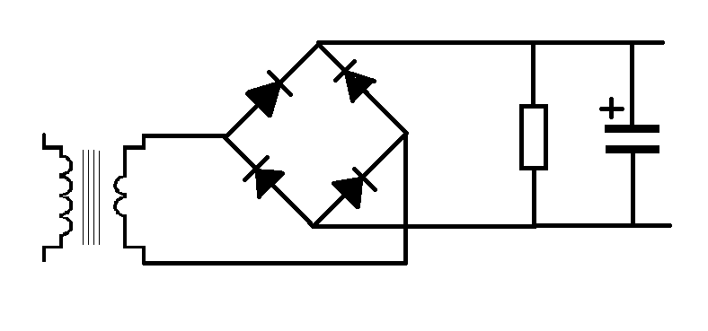
To make the lesson a little easier we made a few assumptions, one of those were that diodes were perfect conductors:
So lets re-visit with realism, and see what the circuit is really doing.
therefore a secondary coil output of 12 volts.
then there was the diode bridge, the forward conduction voltage for a diode is 0.7v this leaves up 11.3volts.
the load of the circuit was 1200Ohms.
and the smoothing capacitor in the circuit was 1 Milifarad
we ignored the diode voltage drop and said that the ripple current was 0.2volts saying that this means that the voltage would ripple between 11.8 and 12 volts.
well, actually it ripples between 11.1 and 11.3 volts because there is a voltage drop in the diodes.
Lets fact it, what good is 11.3 volts. have you ever seen this as the supply needed in a circuit?
What is we really wanted 9 volts.
Well, where do we want the ripple to be, between 8.8 and 9, or 8.9 and 9.1, where am I going to find a transformer that outputs 9.7 or 9.8 volts, so that I can satisfy the voltage drop across the diode and the ripple current and keep enough energy for my circuit? to put it simply, nowhere.
What if I were using germanium diodes, now I need a 9.3v output.
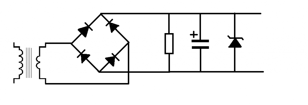
What we use in this situation where we want the power supply to be at a specific set voltage is a zener diode.
The zener diode sits across the positive and negative power supply rails.
in this case we'll stick with out 12v transformer, and use a 9v zener diode.
An even better alternative.
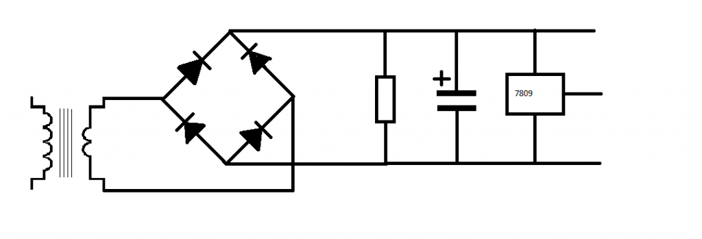
An even better alternative to using zener diodes is to use a voltage regulator.
These components have three legs.
the first leg is the input, this connects to the positive rail of the power supply circuit.
the middle leg is the ground leg, this connects to the ground of both the power supply circuit and the zero volts rail of the circuit that you are powering.
The final leg 3 is the Vout leg, this connects to the positive power rail of the circuit that you are powering.
the 78 series are positive, you apply positive voltage to the input leg and a positive voltage is returned at the output leg.
The part numbers relate to the output voltages:
7805 = 5v
7809 = 9v
7815 = 15v
the 79 series are negative voltage regulators, you apply a negative voltage to these and you get a regulated negative voltage out.
7905 = -5v
7909 = -9c
7915 = -15v


No comments:
Post a Comment