Lessons are boring, I don't need to tell you that though. If you've read through the resistors lesson you may have switched off half way through, you may have just clicked away.
Endless theory is boring. So... lets crack out a few components and start making something nice and simple to illustrate some of this theory.
Equipment
For this lesson, you'll need
>a 9v battery
>a battery clip to attach wires to the battery.
>a small light bulb (and possibly bulb holder).
>and about 3 100ohm resistors, (brown black black).
If you have one then a multimeter that measures voltage would be good.
You should be able to nip into your local radio shack/Maplin/electronics hobby store and get all of these things for less than £5.
Method
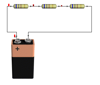
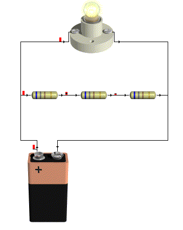
The first thing that you want to do is join the three resistors in series, and attach them to the battery, whether you practice your soldering skills, use a breadboard (as in the little plastic thing), just twist the legs together to form a connection or even use a breadboard with screws and screw cups to hold the components, if doesn't matter, all you need to do is connect the resistors in series and attached then to the battery.
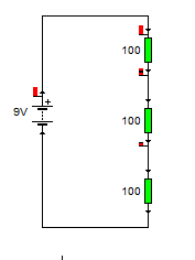
I'm going to illustrate this with a series of pictures, that should show you what you're looking at, and the schematic diagrams that represent what the circuit is.
Next attach one side of your light bulb also to the negative side of the battery.
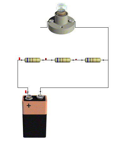
Now you want to attach the other side of your light bulb to the positive side of the battery.
you should see if lights up very bright.
you should see if lights up very bright.

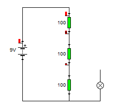
Now remove the connection from the light bulb to the positive side of the battery, and connect the battery to the second leg of the first resistor, you should see that the bulb still lights, just not as bright.
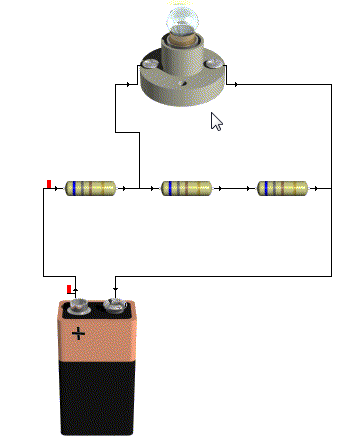
Now remove that connection and connect it to the second leg of the second resistor. the bulb should light a little bit, but it won't be very bright at all.
Extra Activities
If you don't have a multimeter then you should just skip over this bit to the results section.
Now take the light bulb out completely, switch your multimeter onto measure volts in the 20volts range, (or as close to 9volts without being under 9volts depending on your meter).
Touch the (usually black) Comm probe to the negative terminal on the battery and the other (usually Red) lead onto the positive terminal of the battery.
The display should read 9Volts,
Now touch the red lead onto the second leg of the first resistor, it should now read 6Volts.
And if you touch the second leg of the second resistor it should now read 3Volts.
Results
What you have created is a potential divider.
In an earlier lesson we talked about electricity as being a potential energy, (though not in the strict physics sense) this little collection of resistors is dividing up that potential so it reduced as you go down the ladder.
We talked about how power and voltage were linked earlier, the reason that the bulb shines less brightly when a lower voltage is applied to it is because there is less power going to the bulb to make it shine.
There is an equation to work out what the voltage at the given points of a potential divider will be.
That equation is
Vout = (Z2/(Z1+Z2)) x Vin
This formula is using Z in place of R, it may be a little confusing at first, but go with it!
I've made it a little more complicated using three resistors in the example, but that's ok, we learned earlier about how to deal with resistors in series, you just add them together.
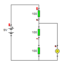
Lets look the voltage on the second leg of resistor 1
We know that the input voltage Vin is 9v
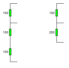
The resistor R1 is 100Ohm, so Z1 = 100Ohm
but what's Z2, (yes if you look at the schematic R2 is 100Ohm, and R3 is also 100Ohm).
For this equation, since we're measuring at the second leg of R1, Z2 is the total resistance of R2 and R3 which are in series, (so we just add them together.)
So lets fill in that equation now.
Vout = (Z2/(Z1 + Z2)) x Vin
Vout = (200/(100 + 200)) x 9
Vout = (200/300) x 9
Vout = 0.666666666 x 9
Vout = 6
That's what we measured!
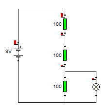
Now let's look at the voltage at the second leg of resistor 2,
This time Z1 is the top two resistors (R1 + R2) and it's 200Ohm
The voltage is still 9v
and Z2 is R3, which is 100Ohm
Vout = (Z2/(Z1 + Z2)) x Vin
Vout = (100/(200 + 100)) x9
Vout = (100/300)x9
Vout = 0.333333333 x9
Vout = 3v
Which again is what we measured! so everything is looking good.
No comments:
Post a Comment