What I want to concentrate on here is a small silicon diode, A say small, as diodes can be bigger and perhaps have different electrical characteristics. diodes can also be made of different things, which again gives them different characteristics.
What is a diode
In the simplest sense a diode is a one way valve for electricity. It'll let voltage flow one way. but not the other way.
So diodes are quite useful things to put into circuits as a reverse polarity protection. protecting sensative components where they can't handle negative voltages, or being connected backwards.
Symbol
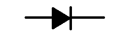
The symbol for a diode looks like an arrow, the arrow shows the way that the electricity flows, at the head of the arrow is a bar, this shows where the electricity is blocked.
So approach from the left you see an arrow sort of saying this way through, approach from the right you see a big bar saying no entry.
The left side is the positive leg, the right side is the negative leg.
Diode use
The easiest way to show what a diode is would be to look at a very simple circuit.
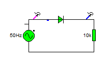
At the left hand side of the circuit there is a sine wave generator, this generates positive and negative signals in a sine wave.
At the right hand side of the circuit is a resistive load, in the middle there is a diode.
There are two probes connectted to the circuit that show you what the wave on that circuit looks like.
Here is the circuit.
the graph below shows the voltage that you'd see if you'd hooked up an oscilloscope to that circuit at the places shown.
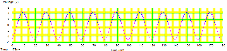
you can see that the original waveform is the pink line, it goes both up and down in a sine wave formation.
The blue line is after the diode, you can see that it's letting through the positive half of the sine wave, but the negative half is being blocked.
This circuit is called a half wave rectifier.
Another thing that you might notice is that the blue line isn't quite as big as the pink line. some voltage appears to have disappeared.
Forward bias voltage drop
That's a bit of a mouthful. so lets break it down.
Forward bias simply means it's connected so that electricity flows through it forward.
The voltage drop of a small silicon diode is usually around 0.6 - 0.8V (say 0.7) but the larger the diode the larger the voltage drop. So a large Silicone diode like you might find in a power supply rated for a thousand million volts might have a voltage drop of 1 - 1.5V
Take a look here http://en.wikipedia.org/wiki/Line_level#Nominal_levels
If you're dealing with line level audio signals a 1.5v drop passing through a diode is going to eat up much of the signal!
The blue line is a little lower than the pink line because some voltage is lost/used up inside the diode.
You may also hear the forward voltage drop referred to as forward bias breakdown voltage, as it's the voltage required in the forward bias to start breaking the bonds inside the silicone to allow electrons to flow.
Reverse breakdown voltage
To be honest, I hadn't planned to include this, however, I've got a bit of a point to including it...
Diodes don't conduct when connected backwards right? Well... that's nearly right, at a certain point when there is a large amount of voltage, the internal structure of the diode will breakdown, and it will start conducting both ways. and the component is dead (I'm not talking about Zener diodes, I'll cover those later).
The point to including it was to say that it's important to chose the correct component for the job that you're doing.
Components can be selected on cost and function, sometimes you have to compromise the function to keep inside the cost, sometimes you have to compromise the cost (spend more) so that you can get the correct function. There is no one component fits all approach to electronics.
If you have 1 diode that you always use, then the chances are that it's not the right diode.
as I said earlier, 1000v diodes just aren't going to work as signal diodes in sensitive equipment, but at the same time small signal diodes aren't going to be any good for creating power supplies.
Selecting Diodes
Selecting resistors was a bit obvious, you picked the right resistivity, and the right power handling then you were more or less done. (it can be more complicated than that, but at the basic level that's all there is to it).
With a diode, it's just as simple, but you don't get it divided into nice easy to spot sizes, or colour codes written on the casing.
What you do get is a data sheet, and somewhere in that data sheet is a chart that looks a bit like this:
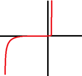
Now I've deliberately left off the values, look at the chart,
In the middle is a standard set of axis, X and Y at right angles to each other.
The middle where the lines meet is 0,
The X axis represents voltage;
From the middle to the right it's positive.
From the middle to the left it's negative.
The Y axis represents the current flowing through the diode.
lets go from the middle towards the right first, you'll see that its only a short distance (0.6 - 0.8 volts in the case of a small signal diode) until the diode "turns on" and allows the current to flow, increasing the voltage past this point doesn't really make a different. (until you exceed another value that you'll find in the data sheet call maximum voltage, or Vmax -at which pooint the component fails).
Going from the middle reading towards the left, you'll see it's quite a big distance that the voltage has to travel before reverse breakdown voltage is reached, when the component fails and conducts both ways.
Now, for a big 1000v rated diode, (that's 1000v Vmax) it'll be 1 - 2 volts forward voltage to turn on, and perhaps -800v to fail when connected backwards.
So can you use this diode to build a power supply (-240 - 0 - +240)? yes
should you use this to construct a circuit where voltages as low as 1.5v are used? no, because it won't conduct at that lower voltage.
For a small signal diode, that turn on voltage might be 0.5v (with a Vmax or 50v), and a reverse breakdown voltage of 30v.
can you use this voltage inside a tiny small signal circuit? yes, it's perfect!
Can you use it in a power supply? definitely not! it can't handle the reverse bias (so won't even act like a diode), it can't handle the forward bias either. as soon as you flip the switch you'd toast this little diode...
The moral of the story is read the data sheets and select your components according to what you want to do with them.
No comments:
Post a Comment