I also mentioned that transistors could be used as current amplifiers.
You'll use a current amplifier when you need a little more power to switch on an output than that output can supply.
We discussed before how the transistor was off, and how it could be turned on.
So, lets make a device that puts a light on with the presence of a voltage, even if that voltage source doesn't have the power (current sourcing capability) to light up the light itself.
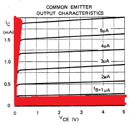
In this tutorial we're interested in two areas of the transistors output, because we're going to use the transistor as a switch we'll either have the transistor in the cut-off region (off), or the saturation region (on) of it's output characteristics. (There are the areas marked in red in the chart below).
The Circuit
What we do is connect the input to the base of the transistor, we use a resistor to ensure that not too much current is pulled from the voltage source that we're detecting.
We'll also put a resistor between the circuit voltage source, and the transistor to limit the current being drawn from the source.
Our light will be an LED, we're expecting that the voltage going to the LED will be 5V at most, but as little as 3v so we look at some data sheets for LEDs and we find that the there are a couple that we can't use, (some have Vmax as 4v), and others will tolerate a higher voltage, but won't light with only 3v.
Eventually we come across the L-53GD-5V made by Kingbright
It has the following characteristics.
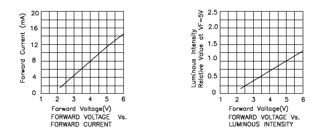
So we can see that it'll be on, and bright at 5v, and it will turn on, (though only be half as bright) at 3volts, (we're interested in sensing 5v Logic levels and 3.3v Logic levels right?)
Elsewhere in the data sheet it tells us that the maximum current is 17mA
We know that our greatest voltage going through the LED will be 5v
So we use ohms law to determine the resistor needed.
5/0.017 = 294
So we really want to make the total resistance between the supply voltage and the indicator LED around 300Ohms
In case you're interested
3.3/300 = 0.011 or 11mA available for the 3.3v logic level to light the LED.
I say the 3.3v, remember this is a current amplifier, not a voltage amplifier. The voltage is going to remain the same as what's going into the transistor base.
Anyway, at 3.3v the LED only draws some 6mA, so there is plenty of current available. (and that 11mA is below the devices max draw of 17mA
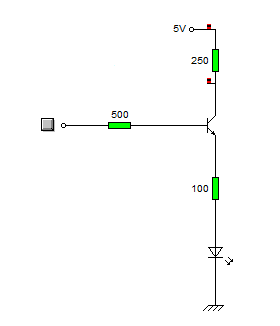
Schematic
Here is the schematic of the circuit.
And here's what happens when a logic level of 1 (+5v) is applied to the base resistor
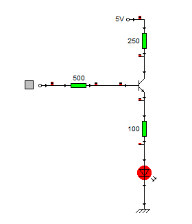
When the circuit is on it pulls around 6ma from the logic source, and the current going through the LED is about 14mA.
Stay tuned to see this idea scaled up!
No comments:
Post a Comment