Thursday, August 11, 2011

Electronics Lessons: The Transistor Simple Circuits (Lab 2)

So in the last lesson I talked about the transistor, I talked about how you could turn the transistor on to a fully conducting state.

I also mentioned that transistors could be used as current amplifiers.

You'll use a current amplifier when you need a little more power to switch on an output than that output can supply.

We discussed before how the transistor was off, and how it could be turned on.

So, lets make a device that puts a light on with the presence of a voltage, even if that voltage source doesn't have the power (current sourcing capability) to light up the light itself.

In this tutorial we're interested in two areas of the transistors output, because we're going to use the transistor as a switch we'll either have the transistor in the cut-off region (off), or the saturation region (on) of it's output characteristics. (There are the areas marked in red in the chart below).


The Circuit
What we do is connect the input to the base of the transistor, we use a resistor to ensure that not too much current is pulled from the voltage source that we're detecting.

We'll also put a resistor between the circuit voltage source, and the transistor to limit the current being drawn from the source.

Our light will be an LED, we're expecting that the voltage going to the LED will be 5V at most, but as little as 3v so we look at some data sheets for LEDs and we find that the there are a couple that we can't use, (some have Vmax as 4v), and others will tolerate a higher voltage, but won't light with only 3v.

Eventually we come across the L-53GD-5V made by Kingbright

It has the following characteristics.


So we can see that it'll be on, and bright at 5v, and it will turn on, (though only be half as bright) at 3volts, (we're interested in sensing 5v Logic levels and 3.3v Logic levels right?)

Elsewhere in the data sheet it tells us that the maximum current is 17mA
We know that our greatest voltage going through the LED will be 5v
So we use ohms law to determine the resistor needed.

5/0.017 = 294

So we really want to make the total resistance between the supply voltage and the indicator LED around 300Ohms
In case you're interested

3.3/300 = 0.011 or 11mA available for the 3.3v logic level to light the LED.

I say the 3.3v, remember this is a current amplifier, not a voltage amplifier. The voltage is going to remain the same as what's going into the transistor base.
Anyway, at 3.3v the LED only draws some 6mA, so there is plenty of current available. (and that 11mA is below the devices max draw of 17mA

Schematic
Here is the schematic of the circuit.


And here's what happens when a logic level of 1 (+5v) is applied to the base resistor


When the circuit is on it pulls around 6ma from the logic source, and the current going through the LED is about 14mA.

Stay tuned to see this idea scaled up!

Tuesday, August 09, 2011

Electronics Lessons: The LED

I briefly touched on LEDs previously in the output devices post a while back.

That post was designed to be a little bit of a primer into all kinds of output devices, to get you thinking about the kind of output that you want to put on your projects.

Now I'm going to start looking at those output devices in a little more detail.
I'll skip over light bulbs for the moment, other than small signal lamps, (torch bulbs) there aren't a lot of light bulbs that are particularly practical to drive from beginner projects, they don't solder directly to boards (requiring bulb holders), and lots require either mains voltage, or the type of current that's really going to burn you if it goes wrong. -I'll come back to light bulbs as output devices later in the series mostly because it'll be necessary to explain a project that I've written up and am waiting to publish.)

LEDs
LEDs are light emitting diodes.

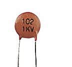
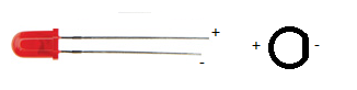
When you buy an LED you'll normally find that appears in a round shape with a dome top.
the round shape has a small ledge of skirt at the bottom of it and one of the sides of this next to a leg is flat.
You'll also find that when you buy the component that one leg is slightly shorter than the other.

The reason that a diode has these characteristics is:
The round body: this is a nice easy package type to make, however, LEDs to come in all different shapes and sizes.
A look here: http://www.rapidonline.com/Electronic-Components/Optoelectronics will help to show just how many different shapes and sizes!

The reason that LEDs generally have a dome shaped top is so that they can be seen from a variety of different angles. if you look at surface mount LEDs these will generally have flat tops, this is so that light guides, that will carry the light from your board to your front panel can fit on top. (a light guide is like a fibre optic cable, except that it's generally made of clear plastic (not glass) and is quite thick (measured in millimetres not microns), and is rigid.

The reason that there is one leg shorter than the other, and the reason for the flat spot on the case is that these show which leg is negative.

The component is a diode and will only conduct one way (when used within specification). and when the diode is conducting it will let you know by giving out light.
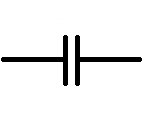
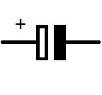
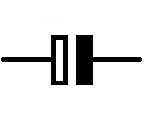
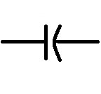
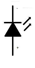
Circuit symbol
The LED is a diode, therefore is shares the same basic symbol as the diodes, (arrow with a flat bar on it) however, as this device emits light there are also two arrows the come out of the diode.

I've only drawn the basic, and now standard symbol for the LED.
however, you may find that there is a circle around the diode symbol, you may find that the arrows have a zig-zag in the middle, the arrow heads may or may not be filled.

Some experiments to try
There are some experiments that you may wish to try.

The first experiment that you should do is either using a power supply with a variable voltage. or using batteries, the examples that I'll use will involve batteries.

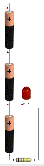
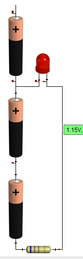
For this experiment you're going to need 3AA batteries, (1.5 Volts).
and a 1K resistor (note this is not the same colour bands as shown in the pictures, that's just a picture).
and a 100Ohm resistor

First connect all the batteries end to end inside a battery holder.
Connect the 1k resistor to the battery packs' negative terminal.
Now connect the other leg of the resistor to the negative leg of the LED
Connect the positive leg of the LED to the first battery in the battery pack.

You'll see that the LED doesn't come on at all.


That's because in order to make the LED light up around 2volts is used up. since you don't even have 2 volts this thing won't light up.

so now connect the positive leg of the LED to the second batteries positive terminal.

Now you've got 3v as a supply voltage, so you've got enough to make the LED light up.
but it'll be very dim.

That's there isn't much current flowing through the device, and the amount of current going through the device is proportional to how bright it looks.

To figure out how much current goes through the device,
start with your supply voltage (3v)
take away the forward voltage of the LED (2v) you're left with 1v

Now use Ohms law to determine how much power is flowing through the circuit
1/1000 = 1miliamp (barely enough to even make it work!)

Now swap your 1k resistor for the 100Ohm, resistor.
the LED should appear to be brighter. the reason is that more current is flowing
1v / 100 Ohms = 10milliamps of current flowing.

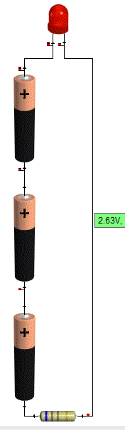
Now repeat the same steps on the positive voltage of the last battery.

This time the LED should be reasonably bright with the 1k resistor and much brighter with the 100Ohm resistor

this is due to the fact that there is now 4.5v supply. (subtract 2 for the LED) leaves 2.5v being dissipated in the resistor.
2.5/1000 = 2.5milliamps.

Before you substitute the 1k resistor for the 100Ohm resistor be sure to take a look at the resistor from the top (birds eye view looking down on the dome,) and from the side.

Notice how it looks brighter at the top. and as you come down to look at the side view, the light almost disappears completely?

Now put that 100 Ohm resistor in the circuit.
When you put the 100ohm resistor into the circuit
2.5/100 = 25milliamps.


You may now find that either the LED is lit very brightly, or that it sort of lit brightly for a bit, but now doesn't work.
It's not going to have exploded! but it might have failed inside. (if you pump enough power through an LED it will explode though!)

Looking at data sheets
To find out why your LED doesn't work any more we'll have a look at the data sheet.

The data sheet that I'm using for reference is:
http://datasheet.octopart.com/L-53GD-5V-Kingbright-datasheet-578943.pdf

Data sheets give you all kinds of useful information, some are better than others, this one just happens to give a lot of information.

So... lets look at the data sheet and find out why the things that were happening above happened.
why varying the resistor made a difference to the brightness, why varying the voltage made a difference, and why the viewing angle made a difference.

We'll start with the viewing angle:
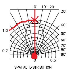
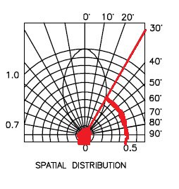
At the end of the data sheet is a diagram called spatial distribution. this diagram is a little confusing at first, but here is now to read it.

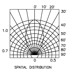
firstly there is a circle at the bottom, you need to imagine that the dome of the LED is inside this circle, now you notice that there is a straight line going up to the marking 0 degrees.

This means that you're looking straight down on the LED.
you can see on the blob shape in the middle touches this 0degree line at the top.
moving along this reaches 1 on the brightness scale.


Now if you change your viewing angle to 30degrees, you find that the blob touches a different brightness line, this line is 0.5
This means that at 30degrees that LED is half as bright as when looking at it from the top.

Now if you move anywhere in the 60 - 90degree region, you'll see that the blob doesn't even touch the line, basically, you'd be lucky to see any light at all.


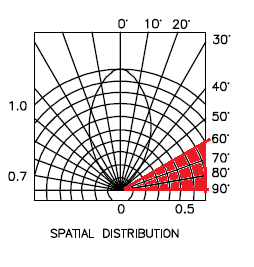
Clearly this is important if you're using the light to indicate anything.

For a start, lets say that your device sits flat at one end of a room, sitting down at the other end of the room your viewing angle will be so shallow that you won't see it at all, OK so this might mean that you just don't know if your cat is inside of outside, no big deal.

Now consider that you're using these LED as brake lights? you're braking in one lane, people behind you can see, but what about people who are only slightly behind and alongside. they can't see that you're braking. what if you try to use these as direction indicators/turn signals? now it's really dangerous as people who need to know your intentions are now given no warning of your intentions.

You might think those LED bulbs are super bright and look cool (and they do) But what if they aren't bright enough? what of the viewing angle? what if they are too bright? this is why (in Europe at least) all car parts have to be E marked, to say that they are tested and approved.

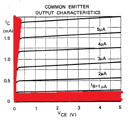
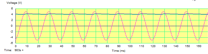
Next let's look at the voltage characteristics:
What these charts are telling us is that as more voltage is applied, the device will get brighter.


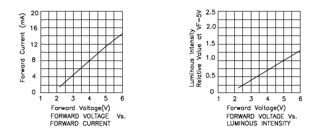
And that as more voltage is applied, more current is passed through the device.
This is exactly what we saw in the experiment, as voltage increased, the device got brighter.
As the current limiting resistor was decreased, more current flowed through the device, which was proportional to the voltage "used" in the device, and so the device got brighter.

Next lets look at the maximum ratings:
The maximum ratings are there to tell us what conditions we can place on the device, this this case the maximum rating tell us a few things.


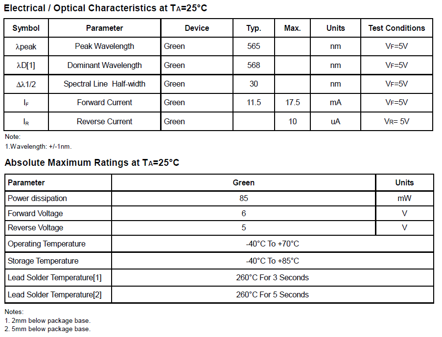
Firstly: forward current (max) the maximum current permitted to flow through this device is 17.5mA (when the voltage is 5v)
This means, select your current limiting resistor such that only this much current can flow.

Then we have absolute maximum ratings:
maximum power: 85mW this means select your input voltage, and current limiting resistor such that less power than this is able to flow, (for lower voltages you can use lower value resistors.)

The absolute maximum voltage rating is 6v, putting more voltage than this through the device will make it stop work, (possibly in a spectacular way.)

Last, but not least we have temperature ratings.
now these are important if you're planning on making a project that'll go in a particular place.
With temperatures of -40 - 60 degrees Celsius, these devices aren't going to be suitable for making stuff that you plan to use in the Antarctic, nor will they be suitable for devices that are left in the baking hot equatorial sunshine.

But lastly, they tell you how long you can hold a soldering iron on the leads before the heat will damage the component. this goes back to the Electronics workbench shopping list of equipment.

If you buy a low power soldering iron, you will have to wait longer for things to heat up. That's because it take the heating element longer to heat up, in the same way that a 2000w kettle boils faster than a 1000w, a 40W soldering iron heats up the components quicker than a 15 or 20Watt one, meaning that you don't have to hold it on the work as long. meaning that you're less likely to damage the components.

Thursday, August 04, 2011

Electronics Lessons: The Transistor

This lesson deals exclusively with Bi-Polar Junction transistors (BJT)
So I covered the diode, a couple of lessons ago.

I'm trying to make these lessons as simple as possible,

I'm trying to keep these beginner introductions to components as simple as possible, trying to keep them at a type GSCE level, so I'm not going to go into exactly how silicon is created and doped to P or N types, I'm not going to go through all the in depth technical stuff that a university course would cover.

These are beginner lessons, assuming that I do stick with this, those more in depth lessons should come a bit later.

The Diode
While I did just say that I wasn't going to go in depth as to how diodes are made it's important to understand a little bit about diodes.

Basically there are three types of silicon in this world.
There is silicon as you find it, that's pretty useless for electronics, then there is doped silicon, doping silicon enables to to be able to transport electrons and therefore allow electricity to flow.
There are two types of silicon, P type, (that contains what we call holes as the transport mechanism) and N type (that contains negative charge carriers [electrons]).

When you put these together you form a PN junction diode, which lets electricity flow one way.

The Transistor


Once upon a time transistors came in metal cases, the little tab on the case was next to the emitter leg, the collector was usually attached to the case and the base was the remaining leg, now they tend to come in plastic cases, and you need the data sheet to tell which leg is what.

The transistor is like two diodes placed back to back, (or front to front depending on the transistor type), arranging the blocks of doped silicon like this allows you to make the transistor act like a switch, but let's not get ahead of ourselves too much just yet.

I'm going to look at the NPN transistor for now.

NPN Transistors
The NPN transistor is called such because the sandwich of silicon is a P-type piece of silicon sandwiched between two N-type pieces. this forms two PN junctions where the P type silicon is shared. (no you can't actually wire two diodes back to back to make a transistor, the semiconducting silicon actually has to be shared).

Each piece of silicon is attached to a leg, and on BJTs these legs are given the name collector, base and emitter.

The collector collects current, and the emitter emits it, (that's overly simplistic, but vaguely true) the base leg controls the amount of charge in the bit of silicon in the middle and therefore controls the amount of current, or electrons that can flow through the device.

If you apply voltage to the base, then you essentially turn the tap on, (assuming you apply enough voltage!).
If you apply 5v then the tap is on. (hard on) the component will what is called hard on.

When you look at the data sheet for the component, you're going to see that there is (of should be!) two values of particular interest, one of these is VBE(sat)

That's the VBE saturation voltage, the amount of voltage needed to turn the transistor hard on.

For BC108 transistors this value is 0.7 volts, (so this or any voltage over this is going to turn the transistor into saturation mode, where it's conducting as much as it can, and can't conduct any more).

You'll also notice that in the VBE values in general there are three values.
Min, Typ (typical) and Max.
Max is the same as the saturation voltage, which we've already covered.
Min is the minimum voltage needed to turn make the transistor start conducting at all.

There are a few more values of interest (depending on the project that you're doing) I'll tell you what these are, and how to use them in a later tutorial.

We've covered that if you apply less voltage that VBE(min), then the transistor won't turn on at all, and if you apply more than VBE(max) that transistor goes into saturation mode.

So what if you apply VBE(typ)?
Again this will be an over simplification, what we'll say is that the transistor is half on.
it's not conducting in it's full on saturation mode, nor is it in it's non conducting off mode. it's half on, go a little over VBE(typ) and it'll conduct a little more, go a little under VBE(typ) and it'll conduct a little less.

Note: That VBE is the voltage difference between the base and the emitter, not necessarily the voltage applied to the base, increasing this voltage above VBE(max) will force more current through the junction and destroy the component.

The transistor is a variable switch, a current amplifier, a voltage amplifier.

Schematic symbols
The symbol for a BJT transistor is a little more complicated than for other components, that's because there are three legs for a start, and they come in two varieties, NPN and PNP.

We'll start with the emitter leg, if you think back to the diode, the symbol for that was an arrow with a bar, the arrow pointed to the N type silicon,

The part of the symbol that shows the emitter is an arrow, the arrow points to the N type silicon.
so on an NPN transistor the arrow points outwards from the base (because the base is P and the emitter is N), on a PNP type the arrow points inwards (because the emitter is P and the base is N)

The Base is a thick straight line.
the collector is an angled straight line.

so here is the symbol for a NPN transistor (remember the arrow point out)

And here is the symbol for the PNP type transistor (remember the arrow points in)

Monday, August 01, 2011

Electronics Lessons: The Capacitor


In the first lesson we looked at resistors, In that post I said that you could think of a battery like a tank full of water, and a resistor as like a small pipe.

Well now I want to change my mind on that analogy and say that you can think of a battery like a mains pipe, and think of a capacitor as like the header tank that sits in your attic.

Capacitors have some pretty cool properties. What I will do in this lesson is explain the electrical characteristics of capacitors, what I'm not going to do is tell you about how capacitors are made, for the purpose of using them it's just not important, and if you want to know, then Google is your friend!

Another Water Analogy
Now I just said that capacitors were like a header tank.
I think that this is a good analogy. You see with a header tank of water, you always have some water pressure coming from your tank.
The tank is exhausted fairly quickly, but if there are workmen in your road who turn off the mains supply, you are still able to turn the tap on, at least for a little bit.

Storing Charge?
Capacitors store electricity, at least that is to say that capacitors store potential energy. They don't have a special electron repository, they have a metal plate inside and charge is accumulated on one side of the plate (as electrons are forced from one plate to another). When you discharge a capacitor you allow it to rebalance it's self (as in you allow the charge across the plates to equalise and become neutral).

Saying that capacitors store charge is technically wrong. There are no more electrons in a "charged" capacitor than there are in a "discharged" capacitor, but it's nice and simple to think of a capacitor like a mini battery, it gets charged, it gets discharged. it's not quite as good as a battery, it doesn't (usually) hold as much charge, and discharges far quicker, so like I said before, if your battery was like your mains water, your capacitor is like a tank full of water in your attic, or on your roof.

One of the first uses of capacitors that you may want to consider is using it to store charge in a power supply.

If you look at the diode lesson, you'll see that we used the diode to create a simple circuit that removed half of an AC waveform, meaning that we could connect it up to a circuit that had a positive and a negative, and that we wouldn't break anything that was sensitive to being connected in reverse. of course the problem with that circuit was that the waveform fell away to zero on the negative half cycle of the AC wave, this would, (in the case of a 50Hz mains signal). mean that you were turning off the power supply and turning it back on quickly every 1/50th of a second (or every 20ms).

A capacitor can be charged on this positive half cycle, when there is plenty of voltage, and then when the supply is in the negative half cycle (or off after the diode), the capacitor can discharge is accumulated charge into the circuit. just like the water tank in your attic/roof when the mains supply is off.

Symbols
Before introducing a circuit, it seems only fair to show you want the symbol that represents a capacitor in a circuit is.

Capacitors come (aside from being made from different things and in different ways) two types.
Polarised, and non-polarised.

Polarised capacitors have polarity, they have a positive and negative leg, non-polarised capacitors do not have either defined positive, nor negative leg and can be connected either way around.

If you remember from the resistor lesson, I said that there were two different symbols that you may see for the resistor, each invented at different times, well, unfortunately, there are more than 2 for the capacitor, (partly because of the polarised/un-polarised components), and partly because someone decided that a different notation would be nice.

You'll see that in the diagrams, sometimes there is a positive symbol, as you can imagine this tells you that the component is polarised, but sometimes there is not a positive symbol, but the rest of the symbol sill looks the same as for a polarised capacitor... you'll find that sometimes people may use a polarised symbol, and not put in that helpful little plus sign, it's still a polarised capacitor, and the rest of the symbol tells you what way round it's connected.

Lets start with the non-polarised capacitor: this will pretty much always look the same, (though the lines may be thicker or thinner.

Now the polarised capacitors, I've drawn these so that they are always having the positive side on the left.


Circuit use
Going back to that simple diode circuit what we do is add a capacitor between the output of the diode and the 0v rail in the circuit. and as described above, the capacitor charges and discharges.

Once again lets look at the wave forms coming out of that.


We can see that the supply circuit is better, our circuit won't be switching off every few seconds, and if we were just trying to light up an LED it'd be good enough. But that blue output wave form is pretty choppy, if we were using that in an audio circuit to drive an amplifier for example the fact that the circuits voltage sags so much means that you'd actually be able to hear it!

The problem here may seem obvious, we need a bigger capacitor.

So lets increase that 1Microfarrad capacitor to a 10uF

Now the output wave form is a lot better. It's been smoothed out as you can see below.

But it's still not perfect. there is still a ripple.

So the obvious answer is to increase the size of the capacitors again.

But I'm going to do it a little differently this time (as it'll help me segway to more information).

And the output wave.


What? You might be saying, what did I do there, I didn't increase the size of the capacitor at all, I just jammed more capacitors in there.

Adding capacitors together
Well you see what I actually did was added the values together.

Capacitors are basically made up of plates, the size of those plates (and amount of plates, and distance between those plates) determines the size of the capacitor.

The bigger the plates, the bigger the capacitance.

I joined these capacitors in parallel, so it's a big like stacking the plates next to each other, I've increased the size of the plates by using multiple capacitors.

When capacitors are connected in parallel, to determine the size of the capacitor you're creating, you just add them together.

C1 + C2 +C3 = Ctotal

So in this case the values are 3 10uF capacitors.
so it's
10uF + 10uF + 10uF = 30uF

So I did increase the size of the capacitor, I just did it in a different way.

There is a different formula for connecting capacitors in series and this is:

(1/C1) + (1/C2) = (1/sum) = Ctotal

Basically, capacitors in parallel have the same formula as resistors in series, and capacitors in series have the same formula as resistors in parallel.