Monday, April 01, 2013

Creo-Elements Tutorial - More gear making

Proof as ever that there is more than one way to skin a cat!

So last week I looked at a way to create a gear on Creo Elements, the approach was to create a segment of gear, that made up a specific fraction of the total gear, then design the teeth profile for a single tooth and then mirror that around a circle to create a whole gear.

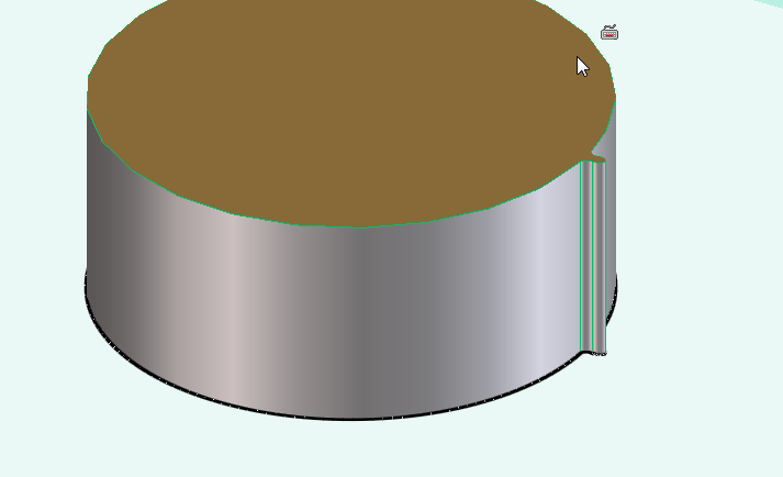
Of course you could start with a circle and draw out the gear as a 2d shape and then extrude it all as one part, or you could make a cylinder and then use the pull tool to extrude the teeth in the cylinder.

The method that I looked at last week is good for designing gears, and other parts that have circular symmetry.

But as ever, there is more than one way to skin a cat.

So now I'm going to cover a new way to create spur gears.

This time the scenario that the part will be designed for is as follows.
I have two axles that are 50mm apart.
I need to link these with two gears, the gears should be the same size such that there is no change in speed of torque in the transmission.

Now the first thing to consider is that if these were rollers they'd both be 50mm diameter, touch and transmit force by friction alone, but as these are spur gears they need to have teeth that mesh into each other.


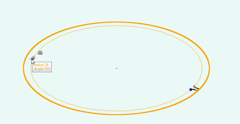
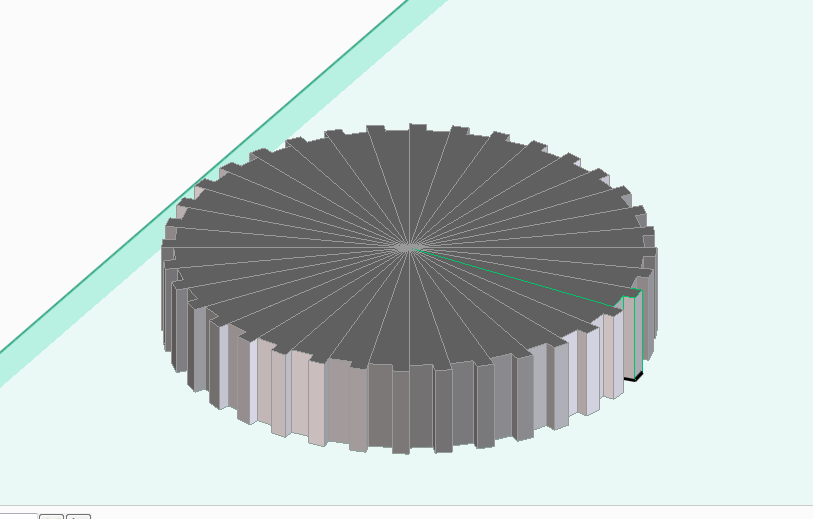
So we start by drawing a circle that's 50mm in diameter. (25mm radius)
then we'll draw another circle inside that with a 24mm radius and finally a circle around the outside with a 26mm radius.


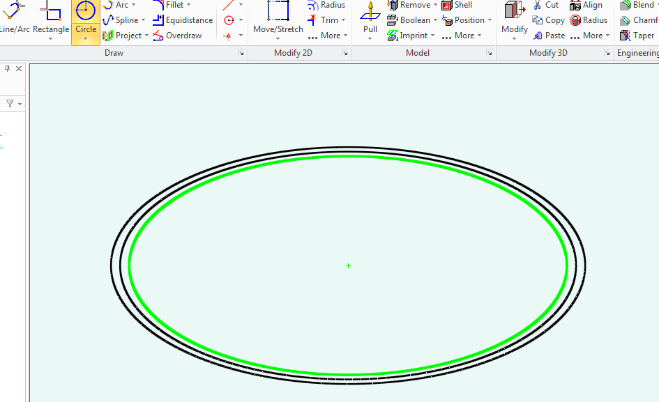
These circles will form and guidelines for the gear teeth, (which will extend out some 1mm over the 25mm radius and nest into pockets 1mm inside of that 25mm radius on it's mating gear.

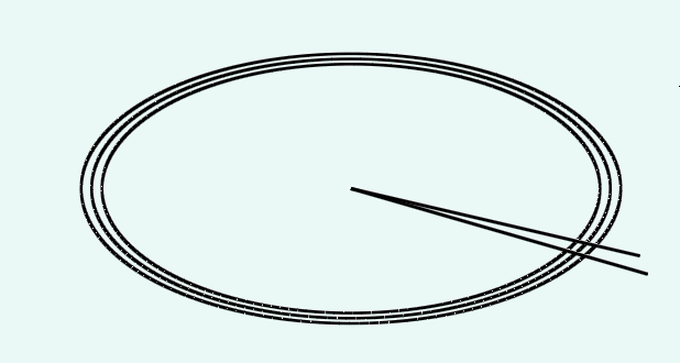
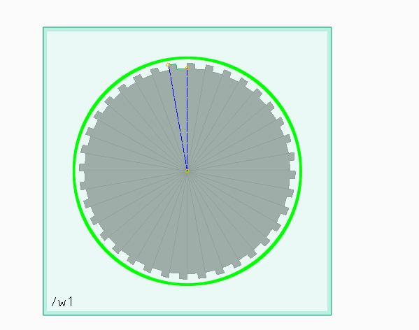
Now we'll add some guide lines for the amount of space our gear teeth will take.
so drawn a line from the centre of the circle along the 0 degrees line, then another on the 5 degrees line.

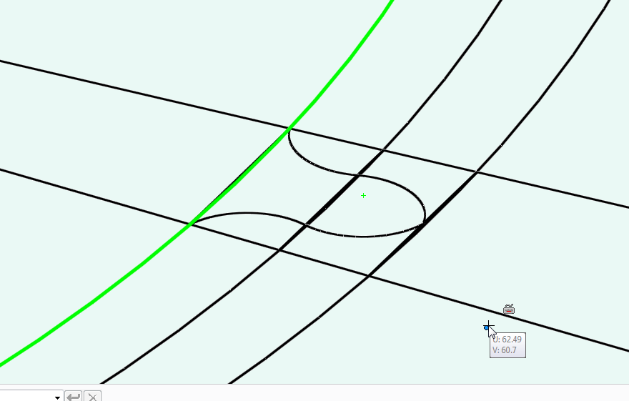
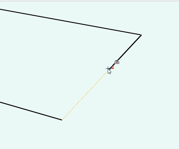
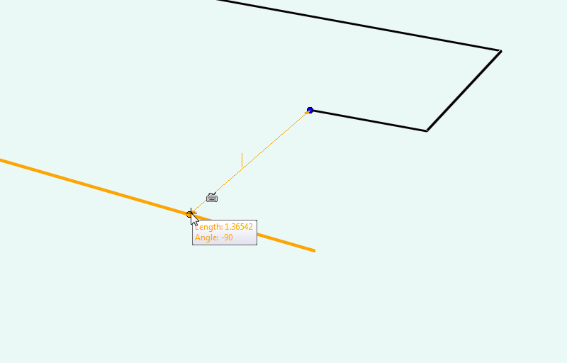
Now zoom in on where you will be making that tooth.

draw appropriate guide lines so that you'll have some points that will snap.
(join the points where you lines on 0 and 5 degrees cross the circle, then halve those lines again. this will form five points 0, 25% 50% 75% 100%, at each circle guideline.

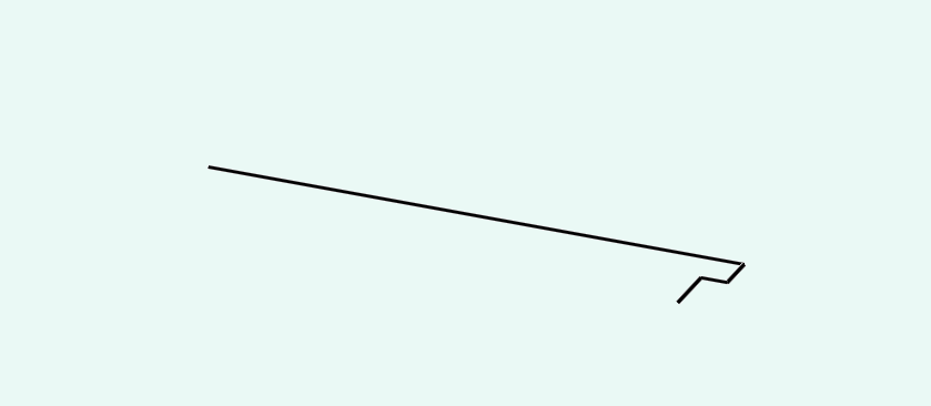
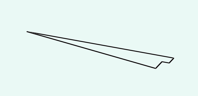
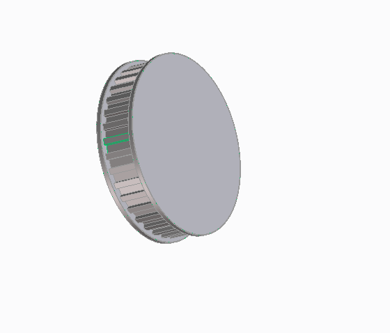
Now use either the line tool, or the radius tool to create a tooth profile.


Now delete all your guidelines inside the outer circle, (leave the circle so that you can find the centre for the arc you'll create next.


Now using the three point arc tool, draw an arc from the base point of the gear tooth, in a wide arc.

Now delete your remaining construction lines so you have a 1 tooth gear.

Pull this single tooth gear to a cylinder.

Now use the rotational mirror tool to create a rotational symmetry to fill on the remaining teeth.

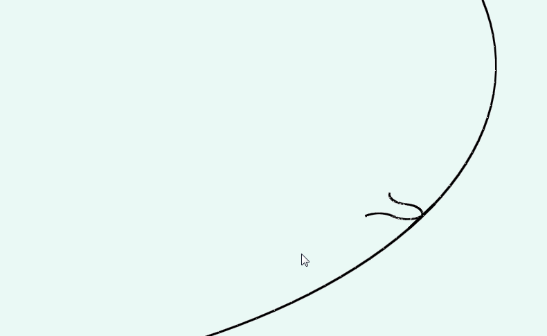
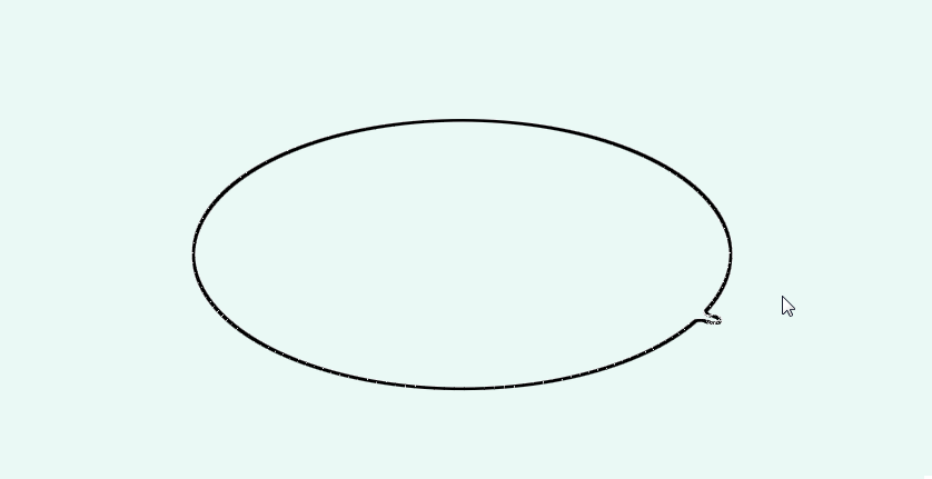
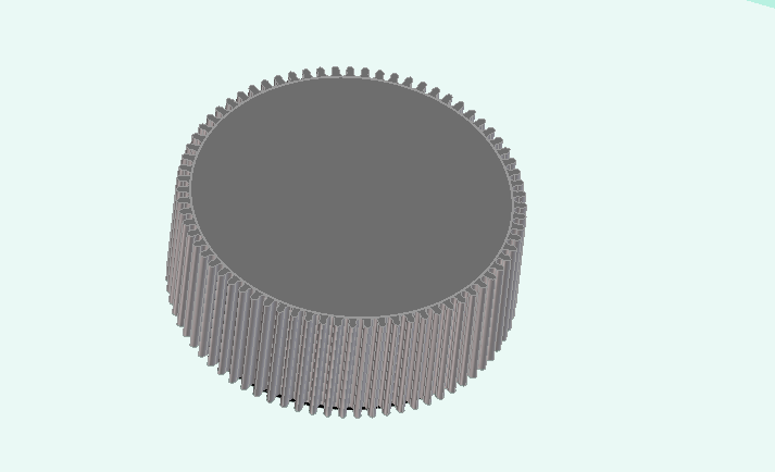
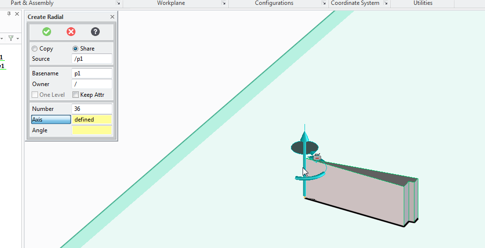
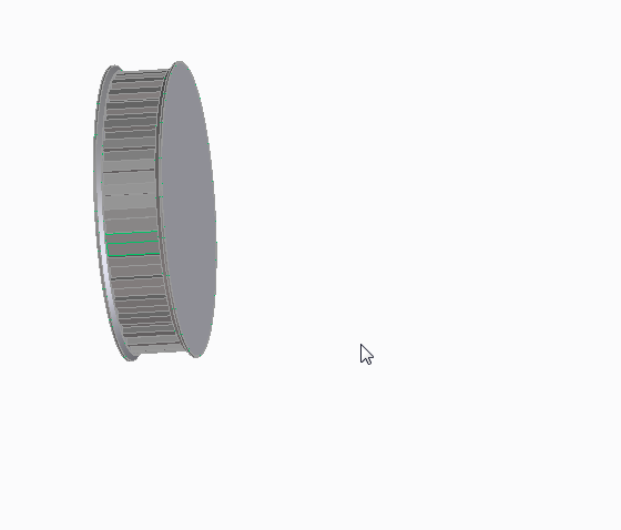
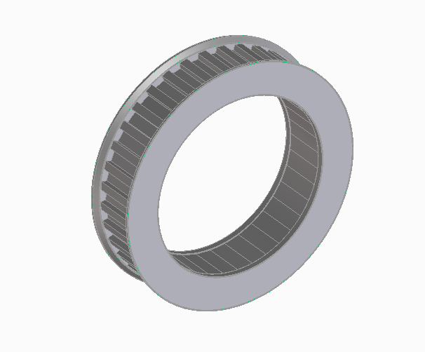
Now you have another gear.


Monday, March 25, 2013

Creo-Elements tutorial -Making gears

So I thought it might be time for another kind of lets teach something blog post.

So,

Making gears with Creo Elements

So I'm going to design an actual part (that I will be using in the creation of my own variant of 3d printer, (I have an idea in my head for this at the moment).

The pulley that I'm going to print now will need to accept T2.5 belt, (5mm thick) and will need to fit over a standard skate bearing (608Z)

So lets have a look at what that actually means.
First we'll have a look at the skate bearing.

These have an outer diameter of 22mm

This means that my pulley wheel must have a hole in it that is 11mm radius.

Next we look at the specification of t2.5 belt.


Basically, any point in the belt to the same point on it's adjacent tooth is 2.5mm.
Each peak is 1mm, each trough is 1mm, there is a slope to the teeth that accounts for the remaining 0.5mm, (a 0.25mm slope)

However, on the pulley I won't put the slope in, I'll leave a sharp angle to allow the belt to bend.

To we're looking at a 1mm crown, and a 1.5mm grove on the t2.5 pulley.
Now we need to figure out the outside diameter of the pulley.

Start by deciding at least how big it must be.

The hole in the middle is 11mm.
We want at least 1mm over the width of this bearing. so we say that the pulley must have a radius of at least a few mm more than this.

Now lets work out the circumference.

14*2 = 32 * pi =88.116
so the outside circumference would be 88.116mm.

I'll round that up to 90mm circumference.
that give me

90/2.5 teeth = 36
each tooth has an angle of 360/36 = 10 degrees

If my circumference is 90, then my radius must be
90/pi / 2 = 14.29mm

I'm going to create a 14.3mm Radius T2.5 pulley wheel, with an 11mm hole in the centre.


So start by drawing a single line that's 14.3mm long on zero degrees.
then a second line 14.3mm long on ten degrees.


Now draw a line 1mm coming into the part, toward the other line.

Then a line that goes towards the centre of the part at a perpendicular angle, that's 0.7mm long (the height of a T2.5 tooth.

finally draw a line directly to the opposite line.


This won't be exactly 1.5mm in length as it's shortened by being closer to the centre of the pulley

now delete the line on zero and redraw to the correct size.


Now you have one thirty sixth of your pulley wheel.

Use the pull tool to make the gear segment 5.5mm tall, (the intended belt width is 5mm, so this adds some space for fit.


You now have a slice of gear.


Next you need to select the structure tab,
pull down the copy part options and select radial copy.

You'll need to copy, 36 times, (there are 36 teeth)
with the axis set at the centre of the pulley
and the angle of each segment is 10 degrees

Press ok and a new gear is produced.

Now delete the work plane.
Now select the circle tool and click on the gear to create a new work plane,

Drag the circle from the centre of the gear to a 15mm radius.

Use the pull tool to make the top of the gear 0.75mm high

repeat on the other side.

Now use the chamfer tool set to 0.5mm to add a slight grove to the pulley wheel edges, this will held reseat the belt if the alignment is slightly out.

now use the circle tool to create a circle with an 11mm radius, and use the pull tool to pull to a depth of -7mm to remove the centre of the pulley wheel.

Now we have a pulley wheel.
It fits over a standard skate bearing.
It has 36 teeth at a T2.5 pitch.

(this will be an idler pulley in the drive system)


This can of course be used to create spur gears as well as pulley wheels, sprockets for use with chain drives, all you need to do is work out the appropriate angle and make your tooth profile fit the job then replicate it.

You can also use this method for making other repeating shapes, for example, spoked wheels, clutch plates, fan assemblies. etc

Monday, March 18, 2013

Breakout board for the Raspberry Pi


I've been talking a lot about my Raspberry Pi recently. That's because I've been playing with it a lot!

On the Raspberry Pi there is a row of pins called GPIO pins, the block of pins is called P1.
These are on most versions of the Raspberry pi the only  input/output pins available.

However on later versions there is a set of 8 pins next to P1 that have no pins soldered in.


So the first thing to do is remove the solder from this header (P5).

The plug for this header is supposed to be mounted with pins facing downwards. personally I don't understand why I'd want to have cables trailing from the top and the bottom of the boards, to me this seems like a crazy idea. I'd much rather have all my pins accessible from the top. especially when I use the mounting holes in this rev 2 board to screw the board down!

After removing the solder I've added 8 new pins to P5


Next there is a new pin header called P6 on the board, this is a set of pins that a reset switch can be attached to.


So now I need to get a plug to attach to these pins.

I started with a 44pin IDE cable.

Start by removing the cable from the connector at one end, put that connector that you removed into connector P1. mark the first un-used set of holes, then using a utility knife cut through this set of holes.
This wastes 2 pins in the connector, but don't worry.


Now using a file or some sand paper you need to sand down the sides of the connector plug so that you can put these two plugs next to each other on the pins of P1 and P5 without them bending the pins.
This is halfway through,


In the end the plugs should comfortably sit next to each other.

Next take the cable, and divide it to split the cable with 26 pins from end of the cable, lay this across the board and trim the first 26 conductors in the cable so that they are about 1 and a half to two board widths shorter than the rest of the cable, also split the first two conductors away from the bulk of the cable.


Now attach the larger half of the connector that was cut in two to the first 26 pins.


Next turn the cable over, and attach the smaller half of the connector to the remaining part of the ribbon cable, so that it sits diagonally next to the P1 connector.

When you fold the cable over, the two plugs should sit next to each other in such a way that they will easily connect to the P1 and P5 headers, (obviously the sides of the connecttor previously sanded away to allow this fit must now face each other!)


Next cut the cap for the plug and glue over the top of the cable to insulate the terminals that have cut through the insulation on the ribbon cable.

And ensure that both connectors can be attached at the same time.

Finally attach a connector to the remaining two conductors in the cable and attach this to P6. I salvaged the connector from an old computer case to it says reset switch, shorting the pins of P6 resets the device so it is apt to use this connector.

Next using some perf board cut the copper track on 22 rows ready to solder the 44 pin header.

Now solder in the header pins to the perf board.
I've used a 42 pin connector which is black, and used a 2 pin white connector to mark pin 1.

After soldering the cable header pins to the perf board you need to solder some pins that will go into the breadboard.

I used single rows of header pins next to the black connector header.


with the pins pushed down into the white block so that they protrude farther out the bottom of the perf board.


Finally the raspberry pi can be connected to my breadboard.


Monday, March 11, 2013

Setting up your Pi

So you've got a raspberry pi, and it's all on line and everything.

The next thing to do is customise the board a little more.

Hostname
The first think that you might decide is I don't want to call my machine Raspberry Pi, perhaps you have two, and they can't both be called RaspberryPi.

Well you'll need to change the host name then...

first to find out your host name type:

pi@raspberrypi ~ $ hostname
raspberrypi


now to edit this you need to edit the host name file, so type
sudo nano /etc/hostname

Delete RaspberryPi and enter the host name you wish to use and then save the file.

next you'll need to edit the hosts file:

type sudo nano /etc/hosts
find anywhere that says Raspberry pi in this file and replace it with the host name of your choice.

Now reboot your device for the changes to take effect.


DHCP vs. Static
Next you'll find that it's all very well to have your Raspberry pi having an IP address just provided by your router. and you've assigned your NAT rule to point to that address, but ,what if the router breaks, or the router restarts, or your Raspberry Pi is off for a while and another machine gets given that IP address?

What you really want to do is assign a static IP address.

To do this you need to enter your network configuration details into a configuration file.

for this example I'm going to suggest that the whole network range is
192.168.0.1 - 192.168.0.254 (The subnet for this range is /24)
and that the router has the address 192.168.0.1
and that it serves DHCP addresses from 192.168.0.2 - 192.168.0.200

So first we need to edit the file that controls the network configuration for the network interface.

sudo nano /etc/network/interfaces

by default this file will appear like this:

auto lo

iface lo inet loopback
iface eth0 inet dhcp

allow-hotplug wlan0
iface wlan0 inet manual
wpa-roam /etc/wpa_supplicant/wpa_supplicant.conf
iface default inet dhcp

you need to tell the machine to be statically assigned not DHCP, so change the line

iface default inet dhcp to iface default inet static


Then you need to say what address to use
so add the line
address 192.168.0.201

(this address is outside of the DHCP range served by the router, so there should never be an IP address conflict)

then you need to say what the subnet is by adding the line

netmask 255.255.255.0

and finally you need to put the gateway address, (which is your routers address

gateway 192.168.0.1

then save and exit this file. then restart your machine

(remember to restart use sudo reboot)

If you've changed the IP address of your Raspberry pi, don't forget to update your NAT rule on your router so that you can have external access!