So,
Making gears with Creo Elements
So I'm going to design an actual part (that I will be using in the creation of my own variant of 3d printer, (I have an idea in my head for this at the moment).
The pulley that I'm going to print now will need to accept T2.5 belt, (5mm thick) and will need to fit over a standard skate bearing (608Z)
So lets have a look at what that actually means.
First we'll have a look at the skate bearing.
These have an outer diameter of 22mm
This means that my pulley wheel must have a hole in it that is 11mm radius.
Next we look at the specification of t2.5 belt.
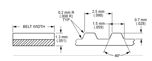
Basically, any point in the belt to the same point on it's adjacent tooth is 2.5mm.
Each peak is 1mm, each trough is 1mm, there is a slope to the teeth that accounts for the remaining 0.5mm, (a 0.25mm slope)
However, on the pulley I won't put the slope in, I'll leave a sharp angle to allow the belt to bend.
To we're looking at a 1mm crown, and a 1.5mm grove on the t2.5 pulley.
Now we need to figure out the outside diameter of the pulley.
Start by deciding at least how big it must be.
The hole in the middle is 11mm.
We want at least 1mm over the width of this bearing. so we say that the pulley must have a radius of at least a few mm more than this.
Now lets work out the circumference.
14*2 = 32 * pi =88.116
so the outside circumference would be 88.116mm.
I'll round that up to 90mm circumference.
that give me
90/2.5 teeth = 36
each tooth has an angle of 360/36 = 10 degrees
If my circumference is 90, then my radius must be
90/pi / 2 = 14.29mm
I'm going to create a 14.3mm Radius T2.5 pulley wheel, with an 11mm hole in the centre.
So start by drawing a single line that's 14.3mm long on zero degrees.
then a second line 14.3mm long on ten degrees.

Now draw a line 1mm coming into the part, toward the other line.
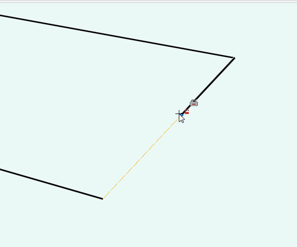
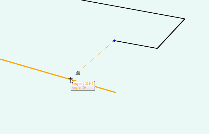

This won't be exactly 1.5mm in length as it's shortened by being closer to the centre of the pulley
now delete the line on zero and redraw to the correct size.
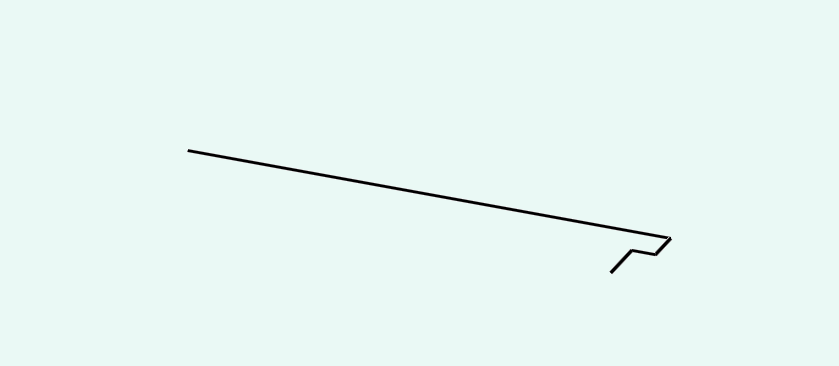
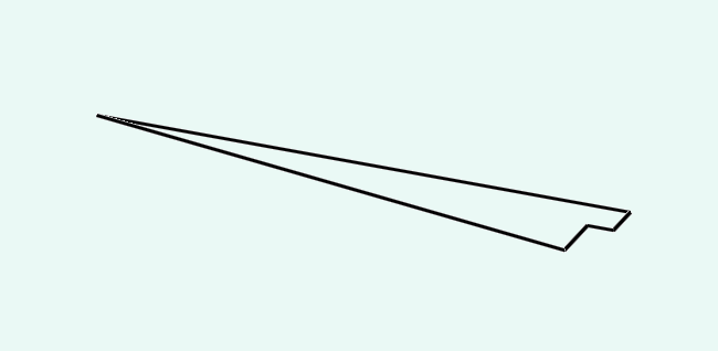
Now you have one thirty sixth of your pulley wheel.
Use the pull tool to make the gear segment 5.5mm tall, (the intended belt width is 5mm, so this adds some space for fit.
Use the pull tool to make the gear segment 5.5mm tall, (the intended belt width is 5mm, so this adds some space for fit.
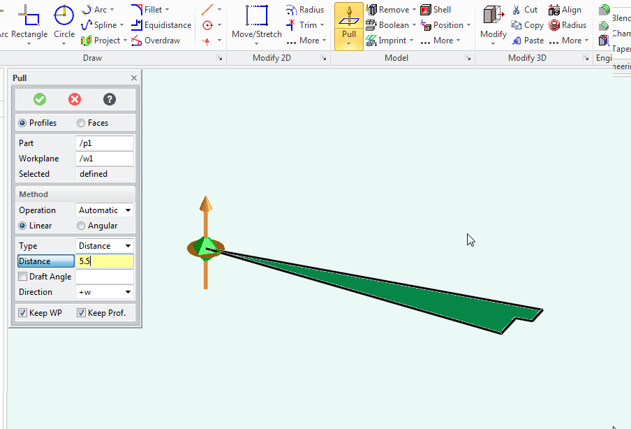

You now have a slice of gear.
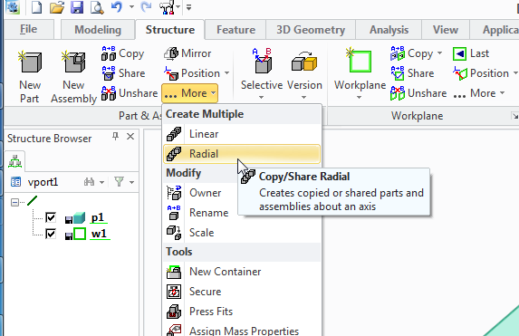
Next you need to select the structure tab,
pull down the copy part options and select radial copy.
Next you need to select the structure tab,
pull down the copy part options and select radial copy.
with the axis set at the centre of the pulley
and the angle of each segment is 10 degrees
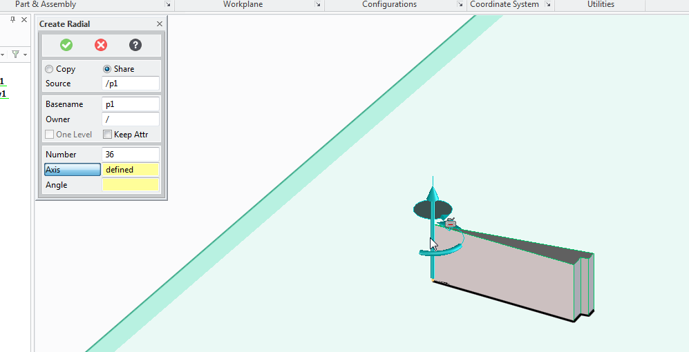
Press ok and a new gear is produced.
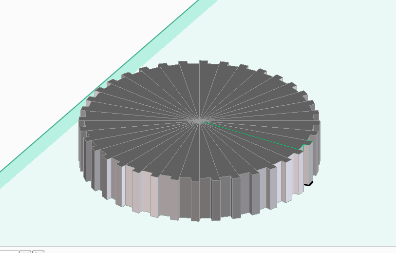
Now select the circle tool and click on the gear to create a new work plane,
Drag the circle from the centre of the gear to a 15mm radius.
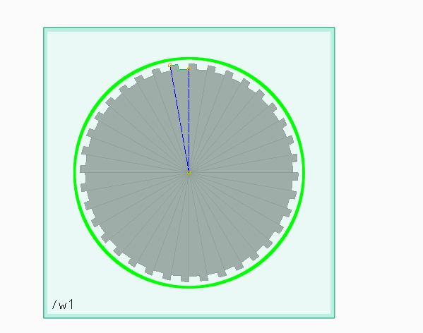
repeat on the other side.
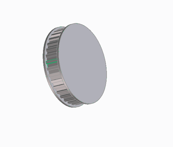
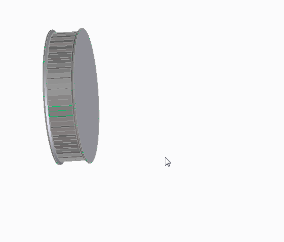
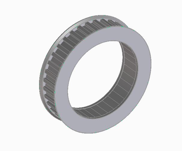
It fits over a standard skate bearing.
It has 36 teeth at a T2.5 pitch.
(this will be an idler pulley in the drive system)
This can of course be used to create spur gears as well as pulley wheels, sprockets for use with chain drives, all you need to do is work out the appropriate angle and make your tooth profile fit the job then replicate it.
You can also use this method for making other repeating shapes, for example, spoked wheels, clutch plates, fan assemblies. etc
No comments:
Post a Comment