Saying that is the non-inverting input was high than the inverting input then the amplifier would have basically the supply voltage as an output. and if it was lower then if would be low.
a better way of saying this is
If Vnon-inverting > Vinverting, then output = +source-2 (if it's a 15volt source that means 13 volts at the output)
If Vnon-inverting < Vinverting, then output = -source+2 (if it's a -15volt source that means -13 volts at the output)
if Vnon-inverting = Vinverting, then output = 0
So you might be asking why is this useful?
Well, to explain why this is useful you have to think about what I was saying in the last lesson.
I talked about the source voltage at the non-inverting input, and the reference voltage at the inverting input.
Say for example we have a series of op-amps.
the inverting leg of each amplifier is set to a different reference voltage, each a small distance apart.
now we connect the non-inverting legs together to form a single common input.
and we connect the outputs to a series of LEDs.
We now have a situation where:
starting at zero the state of each op amp is Vnon-inverting <= Vinverting, so all amplifiers are either negative voltage, or zero volts at the output.
As the non-inverting input rises it will increase above the reference voltage applied to the non-inverting input of op-amp 1, this output will then go positive and the LED attached to it's output will turn on.
as the source rises further op-amp 2 will turn on.
We have created a level meter.
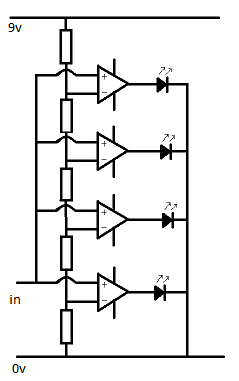
So, in this circuit we're imagining that our input voltage swing between 0 and 8 volts
All the resistors are 1k,
so starting at the top and working down we know that the reference voltage applied to each function is
7.2v
5.4v
3.6v
1.8v
So when the source signal goes above 1.8v, the bottom LED will turn on,
when it goes above 3.6 the second from the bottom LED turns on.
But what id the signal is smaller?
Well, the reference voltage can be anything, if doesn't even have to have the same gap between the reference points.
You could have reference voltages of 0.1, 0.2, 0.5, 1 or anything you want.
You set your reference voltage with the resistor network.
No comments:
Post a Comment