Monday, March 26, 2012

Electronics Lessons: The Transistor Simple Circuits Long Tailed Pairs

This could really be an advanced lesson.
I'm not suggesting that you try to build this, BUT this is the building block of the next major component that I'll be looking at.

Long Tailed Pairs
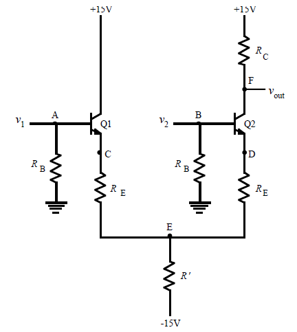
This is a circuit that forms an amplifier, but, that amplifier amplifies the difference between the set of two inputs rather than just amplifying the signal applied to one input, this gives the amplifier good noise rejection since you can (not unreasonably) assume that the same noise would be present in both conductors carrying a signal.

Long tailed pairs of transistors work very well in integrated circuits where they are built on the same piece of silicon substrate, the reason for this is so that both transistors such that they are electrically the same and subject to the same environmental changes in temperature.

As a side note, in Valve amplifiers long tailed pairs will usually use duel triode valves in the same envelope with the same grid and heaters etc.

Long tailed pair amplifiers are also called differential amplifiers, as they can be used to amplify the difference in a signal.

the amplifiers are basically two ordinary transistor amplifiers that share a common junction at Re, and this Re junction is isolated from ground by a second Re resistor.

The amplifier is a difference amplifier because it amplifies the difference between the two inputs.

(V1 - V2) x gain = Voutput


The long tailed pair can make a very good amplifier.
when the input V1 is connected the amplifier will be a non-inverting amplifier, when the input V2 is connected then the amplifier.

In addition to this, if you apply a signal to both inputs the amplifier will cancel common components.
Consider
v1 and v2 tracking perfectly

v1 - v2 = 0
So the output of the amplifier is

(0) x gain = Voutput so Voutput = 0
In a pair of cables the noise induced by external sources (stray EMF perhaps by mains cabling) will be the same, the signal source will not be the same.
Monday, March 19, 2012

Making a notepad

Making a notepad

For a bit of fun I decided to make a small ring bound notepad, and thought I'd write this up.

To create a notepad like this, (fairly useful for making very small sketches, or taking notes)

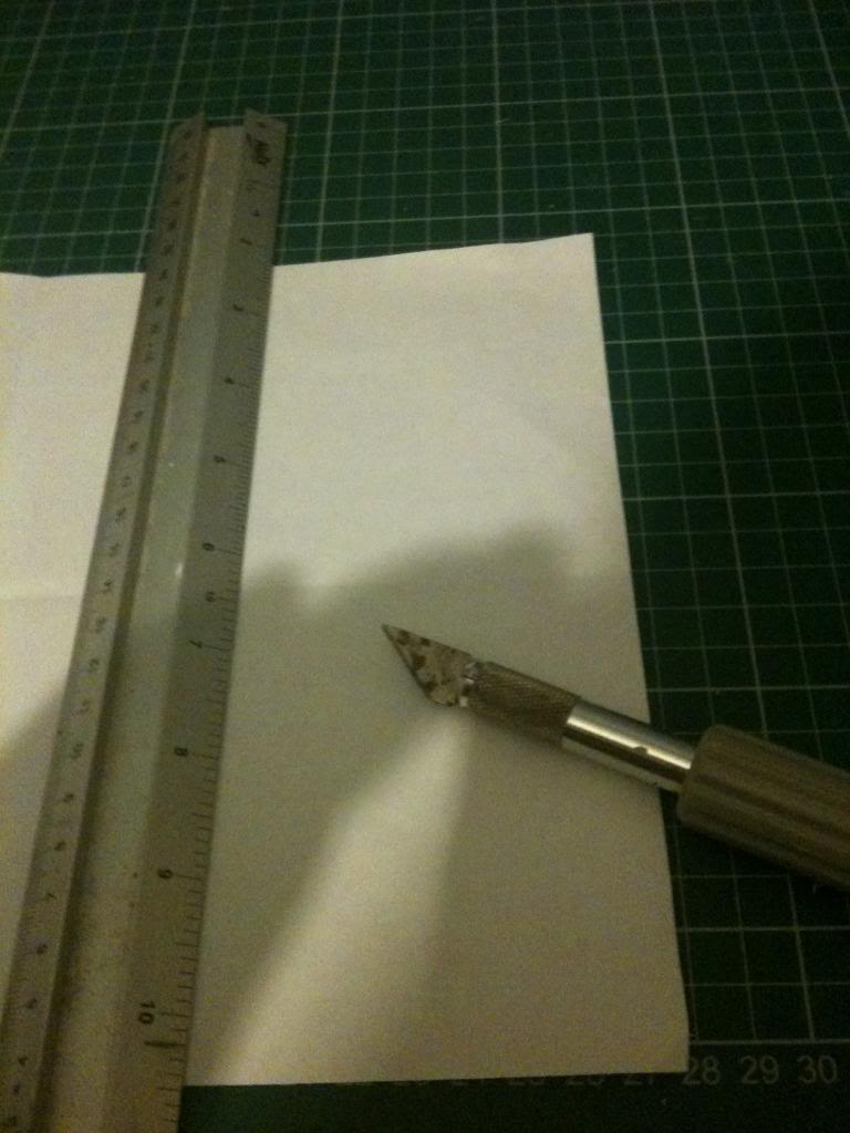
So to create this project you'll need some paper, floppy disks, a straight-edge and knife (or scissors) a vice and a mandrill (a form for bending metal around -in this case a round piece of 25mm dowel) and a wire coat-hanger.


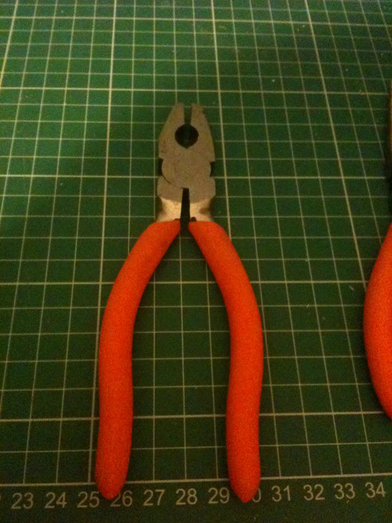
First cut the coat-hanger.
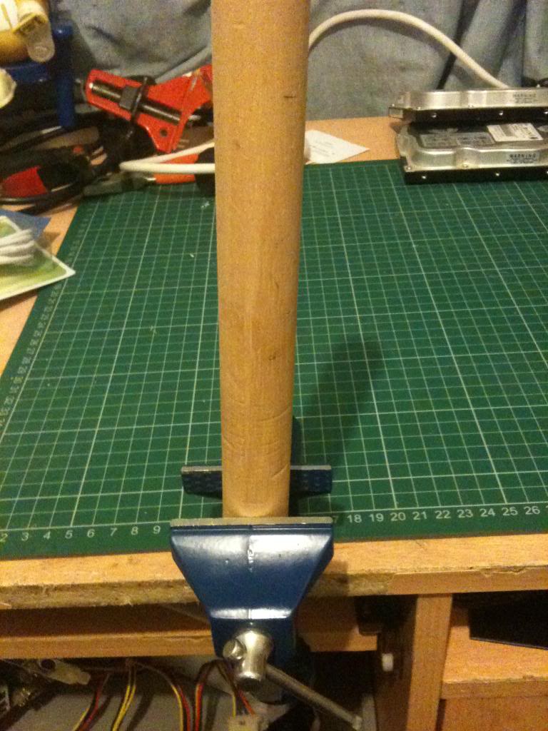
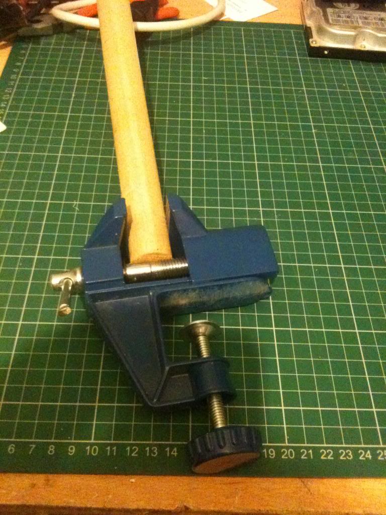
and hold it in the vice parallel with the mandrill.
bend the coat hanger 90 degrees out from the vice.

Now wrap the hanger around the mandrill.
now bend the wire up to be parallel with the mandrill again.

Measure the distance between the holes on the floppy disk, now use this measurement to mark the wire this distance away from the first loop formed around the mandrill.

Once again bend the wire outwards, then around the mandrill, then cut off any excess.

Using the ruler measure the disk, and on some plain printer paper mark out squares the same size as the disk,  then cut out these squares, use a hole punch (one hole at a time) to punch holes in the paper the same distance apart as the loop that you created.

Now start by threading a disk onto the wire loop.

Followed by your paper.

the a disk that forms a cover. (perhaps a cool game disk or something.)

My pad has a windows 3.11 install disk as the front cover, (disk 1) the back cover is the final disk from the install media, (disk 8)

Finally, drill some 3mm holes in a smaller dowel, then use this to secure the rings so that neither your disks or pages fall out of the book. and you have something to hang the book by.


Monday, March 12, 2012

Electronics Lessons: Diode bridges

Sometime last year I gave a basic introduction to the diode, now I'm going to look at networks of diodes and how they are used for half wave and full wave rectification of signals.


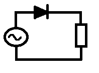
First we'll start with the half wave rectified.


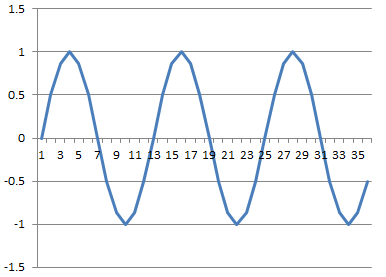
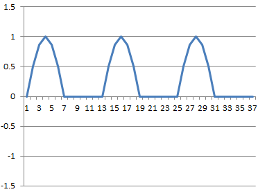
The half wave rectifier is just a diode, this just blocks and therefore chops off the negative part of the power source signal effectively leaving humps with gaps between them.


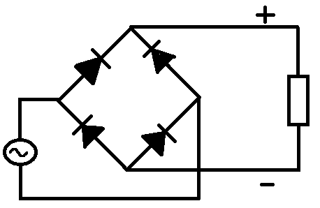
A full wave rectifier is a little more difficult to understand, what you see is a network of resistors in a diamond shape.


When the top rail of the AC signal is in it's positive half cycle the Positive voltage flows through the diode to the circuit, just like the half wave rectifier.
now when the top rail of the AC signal is in it's negative half cycle, the bottom rail is in a positive half cycle, (which is why we have a diode coming from the bottom rail to the positive rail of the circuit.
Clearly the positive rails is now positive, but if the negative rail is directly connected to the AC source it's going to make the negative/earth rail positive too, so the potential difference between the positive and negative rails would be zero.

For this reason we also have a diode to make sure that the negative rail of the circuit does not go positive.


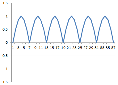
Now when the same AC wave is fed into this full wave rectifier we see that there are still positive humps, but these are a lot closer together.

Monday, March 05, 2012

Electronics Lessons: The Transformer

Firstly, and it is with great sadness that I have to tell you this, but in electronics terms the transformer is not a robot in disguise. -probably would be a lot more popular hobby if it were!!

The transformer is a device the takes alternating current electricity and transforms it, usually either increasing, or decreasing the voltage (and current), but transistors may also be used for impedance matching, (where the primary coil may have one impedance, and the secondary coil has a different impedance, but otherwise the electrical signal is largly unchanged.)

Transformers are basically large coils of wire wrapped around a piece of iron.

As the alternating current enters the primary coil the iron core is magnetised, when the AC current changes direction the electronic field collapses and a new field is created with an opposite polarity inside the iron core.

Move over to the secondary coil and we see a coil of wire wrapped around a piece of iron that has a moving magnetic field, it's kind of like a little generator that contains no moving parts.
(no electricity is generated, you can't get free energy from this thing!)
The creating, collapse and creation and colapse of magnetic fields induced a voltage and current in the secondary coil...


Step down
Probably the most useful aspect of transformers is their ability to change the voltage.
If you look at the voltage coming into your house it's likely to be 240 volts, or 110 volts. but your average electronics project needs say 12 volts.
to get this ten volts the voltage needs to be stepped down.
To do this we use a step down transformer, in this case we have 240volts and we want 12 volts

In this situation we need a step down transformer with 1 winding on the secondary core for every 20 windings on the primary.

The transformer needs to be 20:1

Step up
In the same way as we can step down voltage we can also step up voltage using a transformer.
We use wire the transformer backwards.
if we generate 240 volts and have a 200:1 transformer we end up with 480,000

Power stays the same
We can get more power out of a transformer than we put into a transformer.
We do get slightly less power out of a transformer than we put into it, (due to the creation of eddy currents in the iron core of the transistor that work to heat it up slightly)

We know that power = voltage x current

So if we have 10 watts going into a transformer we have 10 watts coming out
This means that as voltage is stepped down, current is stepped up, and as voltage is stepped up, current is stepped down. -current causes heating in the wires so stepping up the voltage to tens or hundreds of thousands of volts allows the current to be as small as possible, and in long power lines that also means that the power lost due to the heating of wires is also as small as possible.

Our 10 watts of power is made up like this

10Watts @ 240Volts is 0.041Amps
When we step that 240 volts down to 12 volts we decrease the voltage by a factor of 20, so the current increases by a factor of 20 also
10Watts @ 12Volts is 0.83 Amps


Symbol
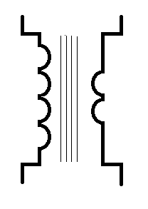
The circuit symbol for a transformer is indicitive of it's construction.
there is a picture of a coil of wire, some straight lines representing the iron core, then some more coils for the secondary coil, there will usually be a legend next to the circuit symbol indicating the winding configuration e.g 20:1