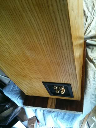
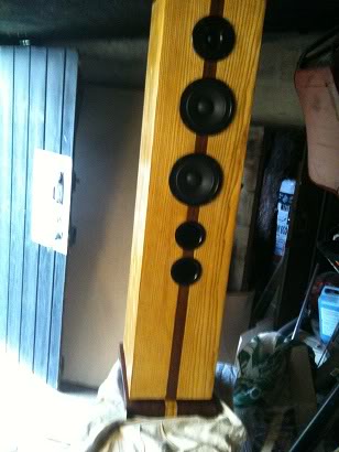
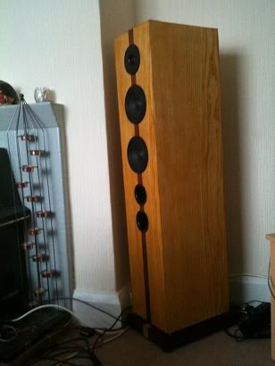
A few months ago I decided that I wanted to build some speakers, so here is how I did it.
Just as a warning (if you;re going to do this yourself), building your own speakers is (generally) cheaper than buying the same equivalent speakers, but, building your own speakers is not cheap.
The design process:Frequency response:The first thing that I decided was that I wanted these speakers to be as close to a flat response as possible. I could have decided that I wanted to listen to lots of drum and bass, and produced speakers with a pronounced bass response, but I decided that I want the speakers to produce as flatter sound as possible, the reasons for this is three fold:
>It'll allow me to be all anal and audiophile about things, listening to tracks as the artists heard them when mixing down.
>If I want to colour the sound, I'll be able to do that with EQ upstream from the speakers anyway.
>It's more of a challenge to try to build studio quality reference speakers, than it is to build just any old speaker.
Dimensions:Next I thought about how roughly big I wanted the things to be, I came up with the following ideas:
>I wanted to build floor standing rather than bookshelf speakers.
>I wanted the treble driver/s to be at ear height when I was sitting down, the reason I specify this is that Bass sounds tend to radiate in all directions, whilst treble sounds tend to be more directional, (this is why in PA systems, high frequency drivers have wave guides attached to them to help spread the sound.)
I measured ear height when sitting down to be ~90 from the floor.
>I wanted the width of the units to be not more than 8 inches, because I feel that this size would be far too imposing to sit comfortably inside an ordinary living room.
Basically, these are for use in a living room, so 18" subs are completely out of the question!
>The depth of the speaker would be open to change with the other constraints of the intended acoustic properties.
Choosing drivers:The amplifier that I have, that I'd like to drive these with can drive a range of speakers from 8 - 4 ohms so any speaker impedance in this range will be fine.
I originally decided that I'd like to use a fabric dome tweeter, (that was roughly 3" in size).
Then I'd like to use a 4" speaker cone for the midrange, then a 5.25" speaker cone for the bass, these sizes I believed would lead to aesthetically pleasing proportions, when spaced evenly, and according to the frequency response/SPL charts available with the units, they seemed to have a relatively even frequency response (more on that later).
However, when I looked closer at the data sheets, the 4" driver had a much lower output SPL at 84dB @1w/1m whilst both the tweeter and the 5.25" driver had an 88dB SPL level @1w/1m
In the end I decided that the 5.25" drivers would suit my needs for both midrange and bass, whilst the tweeter would amply take care of the top end of the chart.
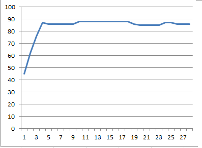
Frequency response:The frequency response of the drivers was basically very attenuated, before having a sharp rise to the resonant frequency (98Hz), where the curve was then fairly even, neither dipping nor rising more than than a couple of dB around the 85 - 86dB mark.
Decibel:The decibel is a measure of pressure, in sound the sound pressure level of the driver determines the kind of sound level it can make.
Lets say for example you have a 100W amplifier, if you want to make something twice as loud you actually need to use a 1000W amplifier, a sound that is twice as loud is a 3dB rise. 3 doesn't sound like a big number, but 88dB is twice as loud as 85dB. So when I say above not rising or falling More than a couple of db around a centre line, it's actually saying some frequencies would appear as twice as loud as others.
Enclosure frequency response:It might sound crazy to anyone who hasn't built any speakers before, but the actual enclosure can do an awful lot to aid and abet my quest for a flat response. I've not got a terribly bad set of drivers, and the fact that they cost less than £10 per cone means that I got a great deal!
The speakers came with data sheets that listed all the Theile small parameters, this enabled me to use a couple of CAD programs.
(one called winISD, which is free, and another program called CAAD, that's a paid for program.)
I use CAAD as it offers lots of information in terms of the response, includes a crossover designer and lots of other features, but it appears to have a limitation on the actual design of the enclosure, in terms of the actual enclosure sizes -it seems to deal, only with the ideal -or at least the copy I have which is not the latest version does. I use WinISD as although this gives less information, the enclosures are a lot easier to tweak to "manageable sizes".
When designing the enclosure, you can change the displacement/size of the box, or style of the box, (4th/6th order band pass, folded horn/transmission line, open baffle, sealed enclosure, or reflex). All of these different designs can mechanically boost or cut frequency bands.
Notably it's only really possible to alter the bass frequency bands, the treble bands will do whatever they like, and are not really affected by enclosure size (as the wavelengths are so much shorter).
Bass Reflex:I decided that I'd go with a bass reflex design, I've designed my enclosure using WinISD, my modelling decided two things for me.
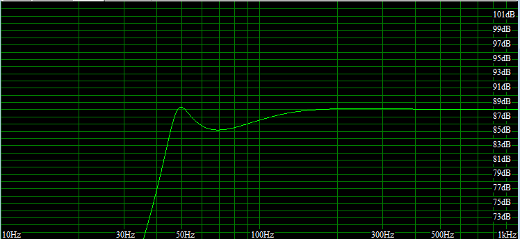
First, as the driver I'm using cuts off rapidly below around 80Hz, I'll want to boost lower frequencies, To do this, I need a large enclosure, and need to use a tuned port, the tuned port allows the backwards pressure of the cone travel to create a positive pressure wave inside the box, that will then add to the pressure wave of the cone on it's forward excursion. (kind of like how an expansion pipe in an exhaust is designed to be a certain size so as to affect the pressure wave of expelled gasses from one cycle and create a vacuum to actually pull more gas out of the combustion chamber on a following cycle.)
However, this does have an effect on the frequencies immediately around this frequency, as the port is tuned, it's this one frequency that is being boosted, this mechanical boost then falls away, however, this mechanical boost to the SPL is falling away at the same level that the drivers SPL is increasing with frequency. (i.e the addition of the two components means that the end frequency response is actually flat).
The volume of my box is 43Litres, this gives an overall height of 76cm and a width of 22cm, the depth is calculated at 25cm.
my ports are 2x 6.8cm circular ports each 16cm deep.

Next we have the problem that if I'm using the same model driver for the bass as I'm using for the midrange, putting that into the same enclosure is going to affect that driver also. The way around this problem is to put the midrange driver and tweeter into a separate speaker cabinet.
But, I don't want a floor standing speaker for a sub, and a bookshelf speaker, so instead I decided make one big cabinet, and have an internal shelf creating the top of one speaker and the bottom of the other. This is called creating a isolated cabinet.
So I model a second enclosure, This time much smaller, I played with some parameters for creating a ported box, but in the end decided that a sealed box would be the way forward.
The reason that I created a sealed box is because in the frequency range that I'm interested in the frequency response of this drive is a fairly static line, I don't want to move it too much above or below that line, mechanically I want to keep it the same so there is no need for a fancy box.
The only design constraints of the second box is that:
>It has to be big enough not to restrict the mid range driver (too small of a sealed box would mean that a huge pressure was built up on the inward movement of the cone, and a vacuum would be created on the outward movement, this would provide resistance to the cone movement limiting the travel and altering the SPL.
>The tweeter must be ~20 cm above the shelf that seals the box to put this at ear height.
I ended up designing a box that was around 15 litres in size, and that was sealed.
the box is (just like the bottom box,) 22cm wide and 25cm deep, the height is 28cm

I can now see that:
>My reflex cab now adequately centres around 88dB for all frequencies over 50Hz, (until the driver drops off).
>My top cabinet adequately centres around 88dB for frequencies over 200Hz, (until the driver cuts off).
>My tweeter has a response that's a little choppier than I would have liked, but reasonable enough for the job.
Driver placement:
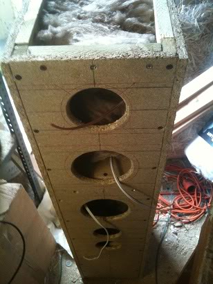
So now I started looking at driver placement, I had decided when I was going to use the 4" driver that I wanted the drivers evenly spaced in a triangle, well, I decided that I still want the drivers evenly spaced, and that everything had to be proportionally spaced.
And here's how I designed that.
I know that my cabinet width will be 22cm, and that the drivers metal frame (outer diameter) is 13.8cm.
So, 22 - 13.8 = 8.2, I then divide that by two to give me a figure of 4.1cm, therefore I know that the spacing either side of my drivers will be 4.1cm, and I decided that I want to space the drivers, this far from the top, of the enclosure, and this much distance between each driver, I'll then half this gap when I get to the ports which as half the diameter of the speakers. (so the distance between these will be ~2cm.
I know that I'll put a lot of internal bracing on the inside of the cabinets to stop the cabinet flexing, (energy spent bending wood is not energy spent creating sound), I'll also be using some loosely packed wadding inside the enclosure to stop any standing waves developing which would cause internal echoes muddying the sound. so I increased my cabinet depth from 25cm to 30cm, (for both the top and bottom cabinets), this allows extra volume to be taken up with bracing, and allows for the material thickness of the board that I'll build the speakers in.
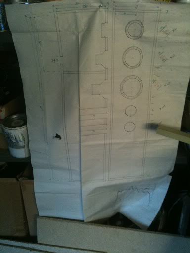
So now I have the box size, driver placements and port lengths, I've ready to draw up a 1/2 scale design that I can pin up in the garage so that I'll have a design to follow I'm also ready to start buying wood to build these from.

You may notice that I've drawn a logarithmic grid at the bottom of the design and plotted the end SPL/Freq chart to include driver parameters and cabinet effects. I'll use the values on this chart later.
Material:
The material that I'm choosing is based solely on price.
Many people argue that the best wood to build speakers from is plywood, as it is a very stiff wood that resists flexing, with the next choice being a medium density fibreboard. I however chose to use chipboard, it's the cheapest of the engineered woods, to put it bluntly, my costs could have doubled using MDF, and tripled using plywood. especially as I had to buy lengths that would fit inside my car to get them home from the store.
For bracing I chose a simple softwood baton 19 x 32mm
Construction:
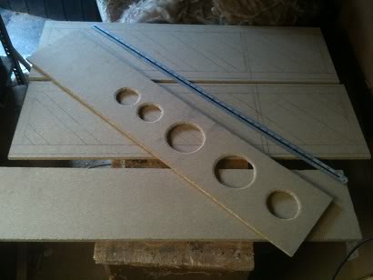
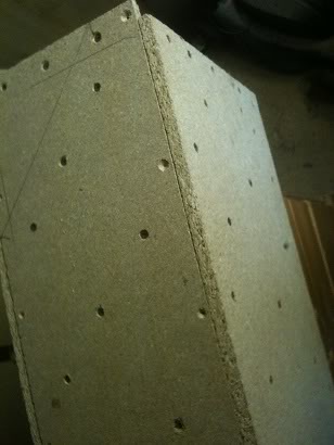
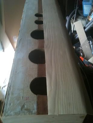
I started by cutting out all the pieces of board that I'd need to use, (14 in total)
the front baffle, 2 sides, the back, the top, bottom and the shelf. (obviously 2 sets to build two speakers!)
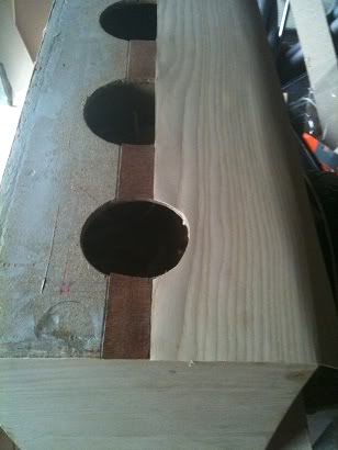
I then marked out and cut the front baffle so that I had an idea of what it'd look like, (at this point if it seemed too big I could go back and re-design. thankfully everything seemed ok.)
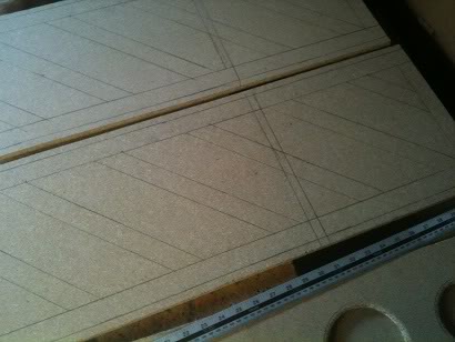
Next I marked the sides for the frames that would form a bases for the front, back, top and bottom to screw to, then I marked my braces.

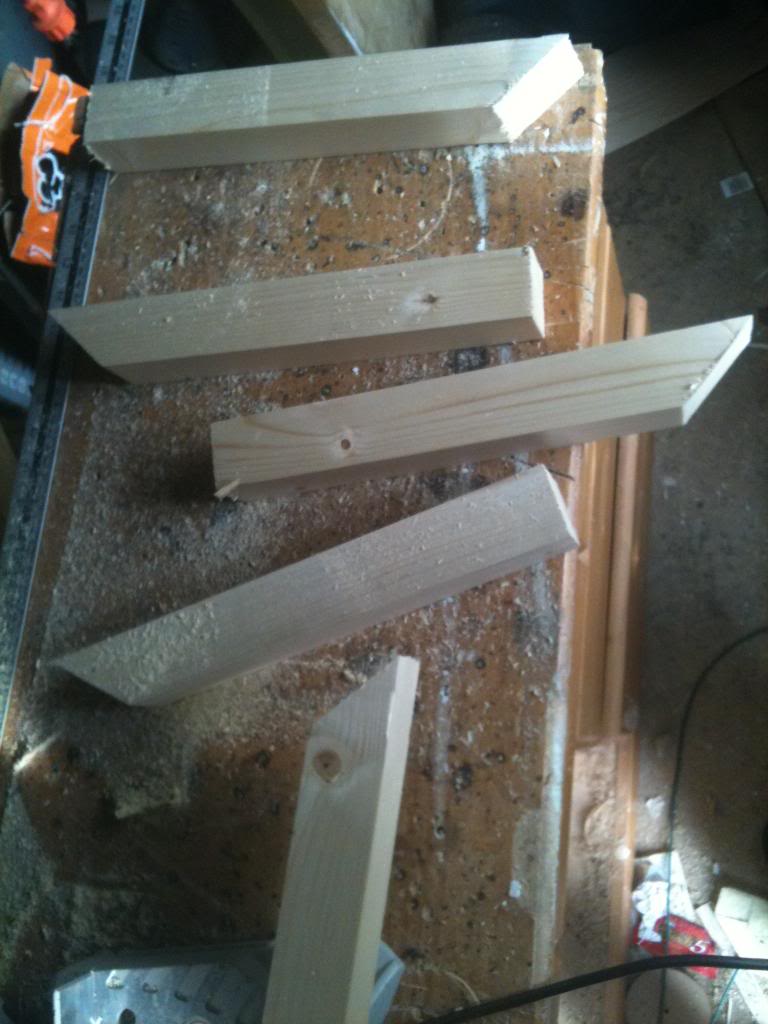
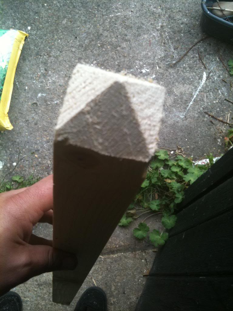
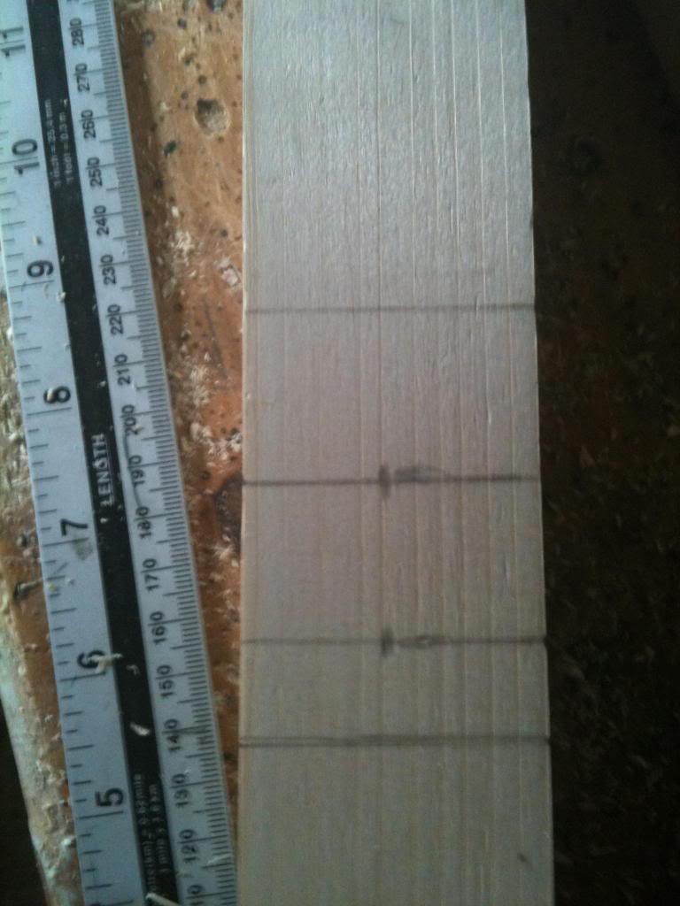
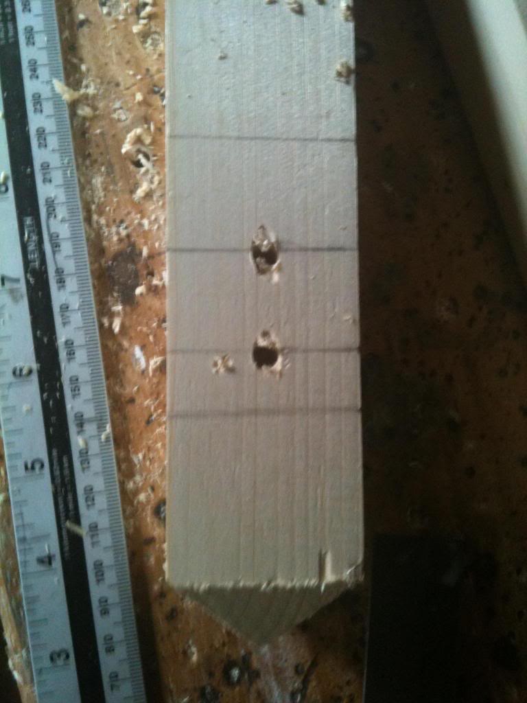
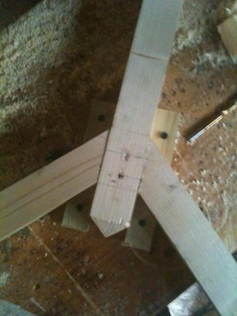
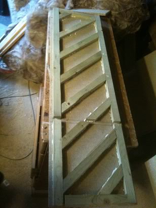
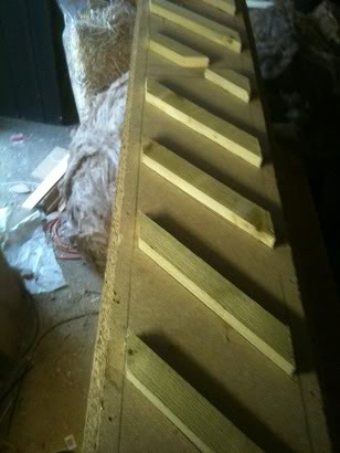
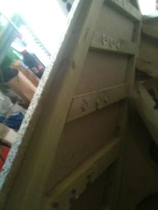
My braces sit at 45 degree angels, and are spaced 15cm apart, there is a break in the bracing where the shelf will sit.
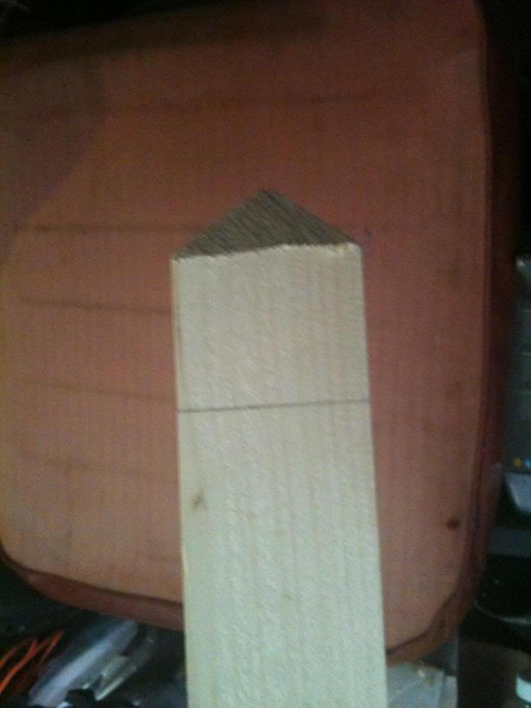
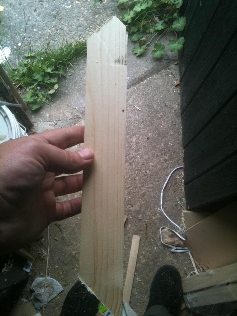
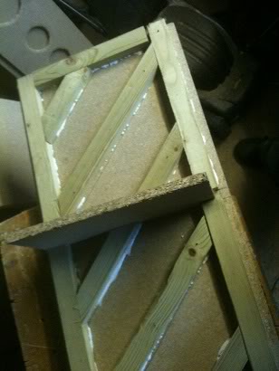
I then cut the batons to length using a mitre saw and glued and screwed these to the side.
the previously flexible side board was now very stiff, I repeated this for both sides.
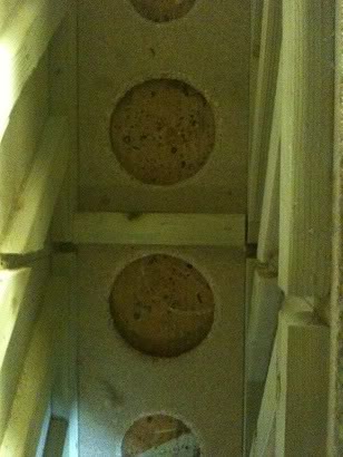
Next I marked a space for the braces on the front baffle (to sit in such a place that they would not interfere with the drivers nor reflex ports.) and glued and screwed these into place.
Finally I put the bracing onto the back also.
Once all the boards were adequately braced I attached the front baffle to the two sides,
I loosely fitted the back in place during the time that the glue was drying such that it'd help hold the box square.
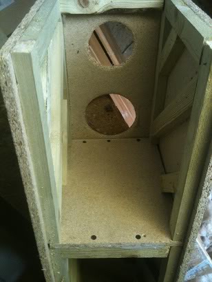
After the glue was dry I removed the back, and fitted the shelf in place, screwing a final baton to the shelf that the back would screw to, (as once the back was on I wouldn't be able to get inside to screw the shelf to a baton that was on the back!)
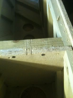
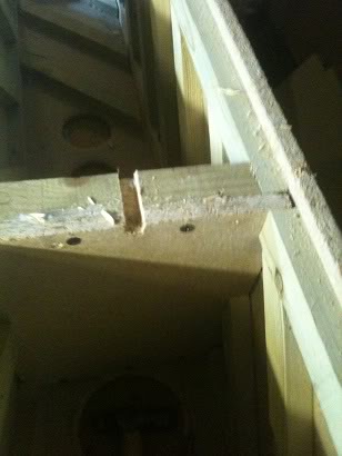
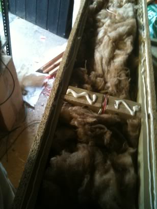
The next task was to cut a small slot in the shelf such that the speaker wires that would connect the midrange driver and tweeter to the connections on the back would have somewhere to sit.
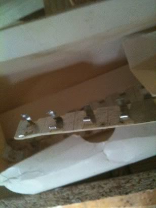
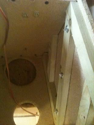
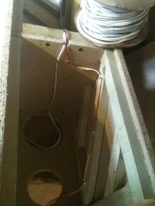
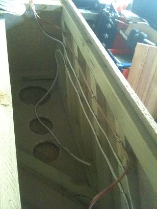
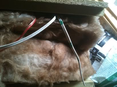
Finally I started wiring up the cabinet, I used small sticky backed cable clips to hold the wires to the side of the box, leaving enough cable poking out of the front of the box to attach drivers to, and leaving enough at the bottom of the box to attach to the crossover network later.
I've used two different colours of wire for the different drivers to help me identify what connection goes where later, the midrange and the bass driver use the same wire, so I've coloured bands onto the bass speaker wire to identify this.
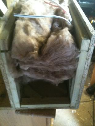
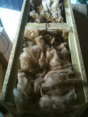
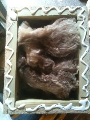
After the wires were in, I inserted my Wadding (a very loose) amount of sheep's wool/fibreglass mix,
This was cut to the width of the box, and then stretched to make it less dense and fill the box.
This wadding stops standing waves from developing inside the box, it would be possible to use egg box foam, basically you're trying to make the inside of the box as anechoic as possible.
Finally the back was glued and screwed into place.
After the glue on this was dry, the top and bottom of the box were added. (after making sure that the box was square of course!)


Wiring:The drivers I'd chosen are 6Ohm speakers with an RMS power handling capability of 40Watts.
I don't want to have to take these speakers apart (ever) to replace the wiring, whilst the wiring would pull out of the clips easily, trying to work around the wadding and clips to install new wire at a later date would be a royal pain in the arse.
So I know that the RMS power I'll be applying to these speakers is ~40W
This means that the peak power is ~57Watts, (peak power is 1.414 * RMS), to be a bit conservative I'll increase this value again, I'll say that I want the power handling capabilities of my speaker wires to be ~80W
The drivers that I am using have an impedance of 6ohms.
knowing that Power = Voltage * Current, and voltage = Current * resistance.
I can say that with an power / resistance = current squared.
So at 80w, there is around 3.7amps of current going through the wires.
looking at this
reference chart I can see that for 3.7Amps, (looking at the power transmission column) I need at least AWG gauge 16, (which is between SWG gauges 17 and 18 [so you'd use the biggest which is 17!] or 1.29mm diameter). (Yes, I'm look at lengths for transmission, I wouldn't say that lengths of over a meter are chassis wiring.)
Speaker stands:When I started this project I had the thought in my mind that I'd just get some spikes for these speakers, and that would be that.
However, as I progressed through this project it became clear that spikes would be a bad idea, the speakers are heavy! spikes would just make huge holes in the floor/carpet so I had to come up with a different solution.
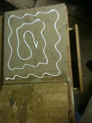
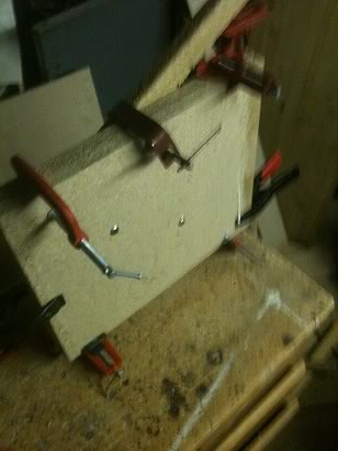
I decided that I'd make a kind of plinth for the speakers to sit on, to do this I cut a sheet of 3/4" chip board into two squares of equal size, that size was ~1" wider than the speakers and ~2" deeper. these two squares were glued together to make a 1.5" thick slab for the speakers to stand on.


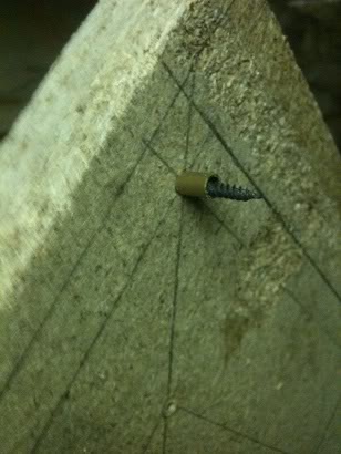
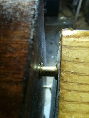
I decided that I wanted my speakers to float above this plinth, and decided that rather that sitting the speaker on spikes above this plinth, I made stand-offs using two brass screw cups and a short length of brass rod as a spacer. This spacer is placed around 1/2" into the bottom of the speaker (from the edge).
At this point I have not attached the plinth to the cabinet.
Now all the screw heads (sitting slightly under the surface as they were countersunk) were filled with wood filler, and sanded, In theory if, with care I could have painted the speakers now with a coat of primer and a nice black gloss finish and they'd have matched the TV.

But I have a very different plan for these speakers.
Veneer:
I have to admit that paint would have been a much much cheaper option than using real wood to finish these, however, real wood looks a lot nicer than paint.
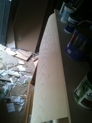
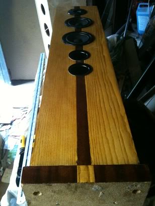
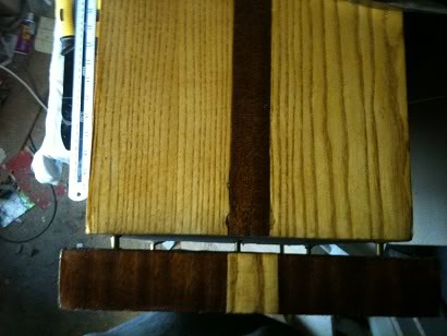
I've chosen to use an ash veneer (white ash), I've also decided that I'll put a strip of mahogany down the centre, and I'll reverse that motif on the stand.
I started at the side, then did the back, then the other side, finally leaving the front to do,
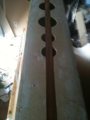
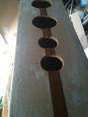
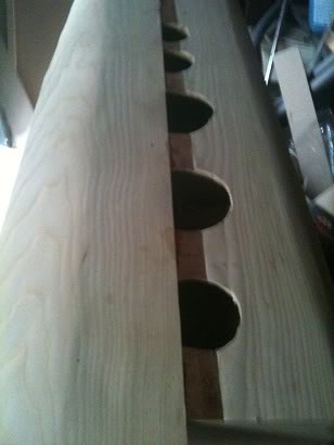
I started the front by first applying a 1 1/4" strip of mahogany wood to form a strip down the side, then I attached the ash veneer on either side of this, this means that the edges of the front, overlapped the front ensuring that the joint wouldn't be visible, then I completed the top. the base of the speaker is not covered because it will be on the floor and never seen.
As any part was attached that would have a hole in it was attached, the hole was cut out, this is because it made it much easier to see where the hole was when I could see half the hole than if I just had a completely covered box and had to measure where the holes were again.


I experimented with two ways to attach the veneer, either using a contact adhesive, where you spread the wet adhesive on both the box and the veneer, wait for the glue to dry to the point that it becomes tacky, then mate the two pieces together, However I found that the contact adhesive that I was using (which I normally use to attach carpet to PA speakers, didn't really give me enough time to adjust any pieces before the glue set and I couldn't adjust anything.
In the end I settled for using a PVA glue, and just being able to only attach one side per day leaving the glue overnight to dry, whilst applying plenty of weight on top of the side to hold the veneer flat.


After the glue dried I sanded the box to ensure that it was smooth, and that the edges of the veneer on the corners had a slight chamfer, any cracks in the finish were filled with a white wood filler and also sanded smooth, then I applied a French polish finish. The French polish that I used was a blonde polish, the reason I used white filler is because the polish applied an even stain to both the filler and the wood.
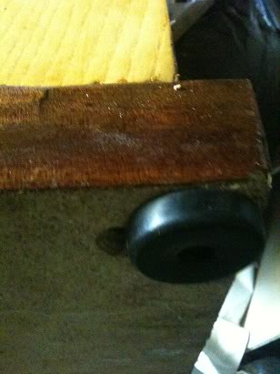
(I've covered how to apply a French polish in an earlier craft tutorial).Finally the plinth was attached to the base of the enclosure, with the brass stand-offs, and rubber feet were attached to the plinth. The idea is that, hopefully, this will isolate the cabinet from the floor, which ideally should provide a better sounding speaker. (energy is absorbed in the rubber feet rather than being transmitted into the floor, the floor is going to vibrate, and the vibrating floor would create it's own sound. It'd rather defeat the point of all the careful design to get a flat response if you let the floor be an unregulated speaker as well.


Ports:
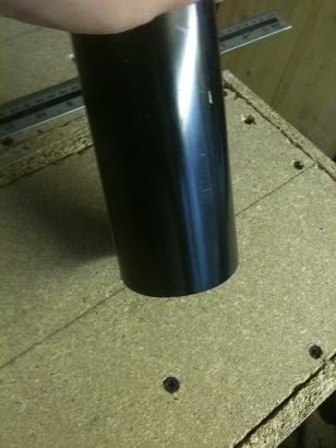
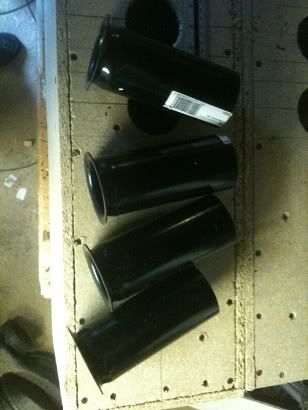
My reflex ports were 16cm in length, and 6.8cm, I chose 6.8cm as this is a standard sized downpipe for guttering, whilst you can buy pre-made speaker ports from speaker shops and manufacturers I decided that I'd make my own, the reason for this is a pure cost decision.
To make the reflex port I cut the downpipe to 17cm lengths I used a mitre saw to ensure that the cut was a true 90 degree cut.
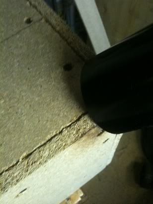
After cutting the tube I heated the end of the tube gradually with a heat gun, using the corner of the speaker (before veneering it) as a mandrill to expand the pipe. when the edges were slightly flared I changed to using one of my hole saws as a mandrill, I did this as the corners were less sharp, (and less likely to tear the PVC pipe, also, since the hole saw is made of metal, it heats up as the air from the heat gun hits it, this means that as I'm turning the pipe the pipe doesn't cool down as much.
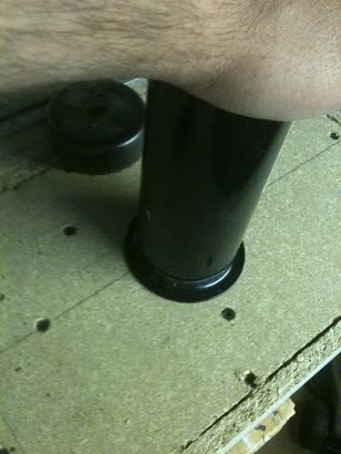
When the pipe was both flared and malleable enough, i pressed the pipe down onto a flat surface, creating a flat flared port at the front.
I've got 4 ports, so I went through this process 4 times.
The flare allows adhesive to be spread around the side of the pipe and underside of the flare, meaning that there is a much larger contact surface to hold the port to the speaker enclosure than if I'd just used straight pipe without the flare.


Crossovers:
Knowing the frequency response of both my speakers, and the cabinet I now plotted the values in Excel, The program didn't give me a logarithmic graph, (it might be able to and I just might not know how).
I had three columns for my bass mid and treble, and was able to take values from my speaker data sheet, combine these with the values for my enclosure gain and attenuation, to find the final values of how these speakers would sound in the final enclosure.
From here, all I needed to do was select cross over points, and the fall off rate for the waveform.
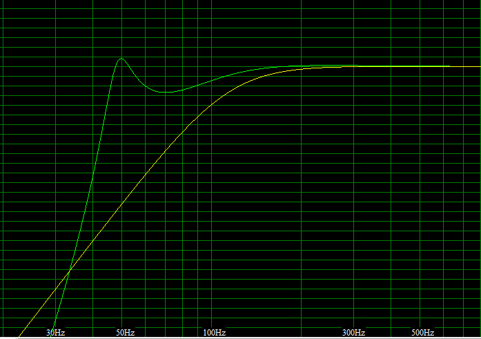
I loosely decided that I'd like the bass response to be 0 - 200Hz, mid to cover 200 - 2000Hz and the tweeter to take over with everything after that as the values for the cross over points, and that a 6dB decay would be enough. (so I would be using a simple butter worth filter.)
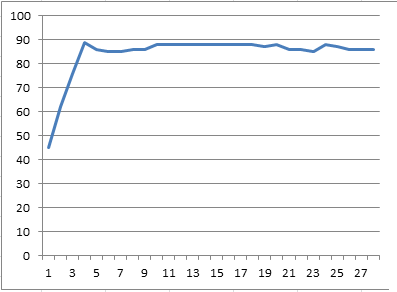
This would make the calculated frequency response appear as this:

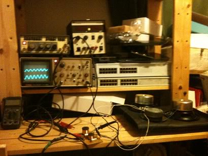
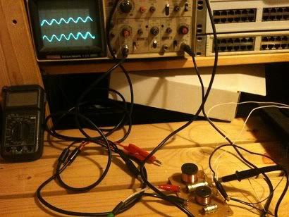
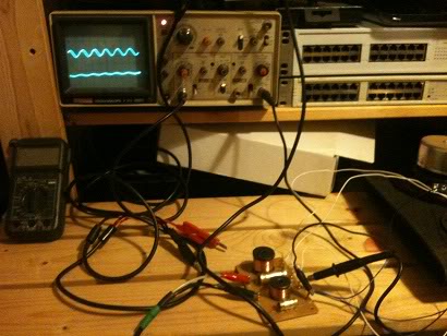
I investigated some components prices to either buy components for the crossover, or the wire of enamelled wire for winding my own inductors, but in the end found a pair of crossovers that I'd once bought for a different project and never used.
The only problem was that I didn't know what the values for the inductors were, and so didn't know the cross over points.
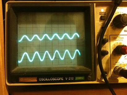
In order to get around this problem I used my signal generator and oscilloscope, setting frequencies of
10Hz, 20Hz, 30Hz, 40Hz, 50Hz, 60Hz, 70Hz, 80Hz, 90Hz, 100Hz 200Hz, 300Hz, 400Hz, 500Hz, 600Hz, 700Hz 800Hz, 900Hz 1KHz, 2KHz, 3KHz, 4KHz, 5KHz, 6KHz, 7KHz, 8KHz, 9KHz, 10KHz, and 20KHz in turn and measuring the output at the output for each driver.


From this I was able to find that the crossover points on the cross over that I had was ~200Hz, and 6000Hz, Which, were a little way off from my Original selected values, however, when I changed my spreadsheet to use these values I found that the response would still be fairly flat. and I would not have to devise any attenuation network.

Bi-Wire:
I had decided early on that as I was only using 40W drivers that there was at least a slim chance that sometime in the future I'd probably want a second amplifier, if not to add more sound, then to add more headroom and allow me to turn down the amplifier.
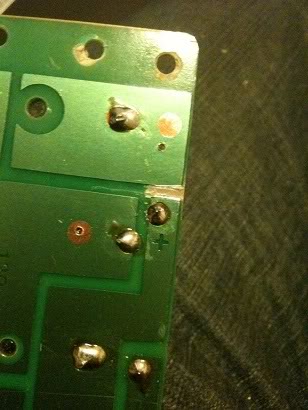
The crossover that I had was a single wire design, to make the cross over bi-wire able I had to cut a trace on the PCB, then drill a new hole and cut back some of the lacquer to be able to add a second input just on the bass side of the PCB.
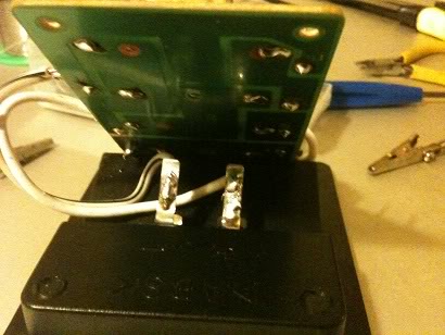
I also drilled two new holes in the PCB next to the heaviest inductor so that I could mount the crossover directly to the speaker binding posts. Rather than having to screw these to the bottom of the case (through a tiny hole that I could only fit one hand into and couldn't see through).
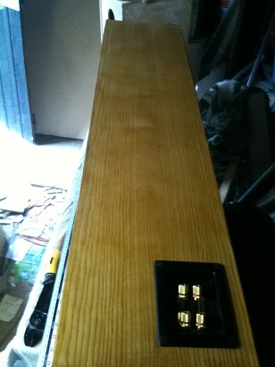
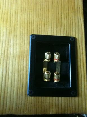
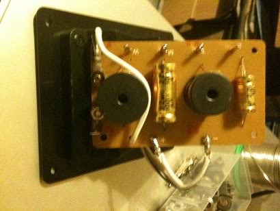
After the cross over was mounted, I attached the wires for the speakers to the posts on the crossover, and screwed it to the back of the cabinet.
Then the speaker cones and tweeter were attached to the wire and screwed into the cabinet.


And the finished cabinet is here.

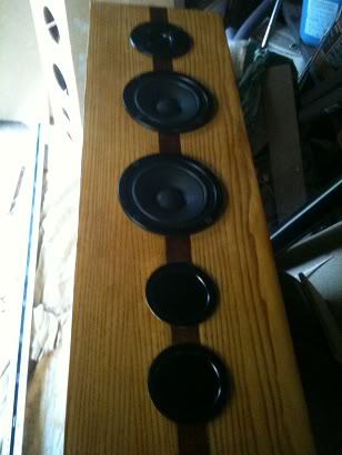
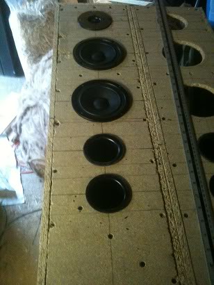
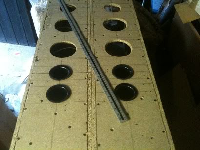
The more keen eyed may have seen that the mid and bass drivers were not centred in previous pictures when they were just loosely attached, in this final picture they are centred so that there is the same distance between each driver, and the same distance to each edge.
Costs:
The total cost was higher than I'd first intended. my goal was to try to build the speakers for less than £100, I did fail in this goal, even though I had lots of the materials already waiting to be used up from previous projects.
The wood, was bought in a large sheet 4 feet * 6feet, with a second 2foot x 6 foot sheet needed
the price for this was:
£9.99 for the small sheet.
£10.99 for the big sheet (yes, twice as big, but only a pound more).
(I had most of the wood already bought)
A pack of wooden baton.
£5.40 for 8 x 19x32mm in 1.8m lengths
(I had this laying around)
The wool wadding was left over loft insulation that I'd bought for something else, though this was £5 for the whole roll.
The screws cost £10 for a box (I already had these.)
The screw cups used in the stand-offs were £2 for a box of five hundred
The wood filler costs £3 for a tub. (I already had this.)
Glue costs ~£5 (I buy this in buckets and decant it into smaller bottles to use as it's cheaper that way. -so I already had this)
A sheet of 2/3" chip board used to make the plinths would also cost £9.99 (but I already had this -in fact this was made from the sides of a huge PA speaker that I once made and had to pull appart as I had nowhere to store them).
The length of brass rod used for the stand-offs is £5 per meter, I used about 12cm of this, but clearly you have to buy the whole meter! (and once again I already had this)
The veneer cost £50 including deliver for the Ash veneer, the Mahogany I had left over from an earlier project but would cost £10 for a sheet
The drain pipe used for the ports is around £5 for a 2m length, again even though you don't use it all you have to pay for it! (I already had this from previous speaker builds where I've made ports!)
The rubber feet are £2.99 for a pack of 4, (you need two packs).
The binding posts used on the back are ~5 each
I seem to remember that the crossovers cost me ~£5 for the pair a long time ago, But a quick look around suggests that £10 is not unreasonable for crossovers that don't have epic power handling capabilities
The speaker drivers 5.25" cost £7.99 each (and there are 4)
the dome tweeter cost £5.99 (and there are 2)
Speaker cable costs £1.25 a meter and there is around 4meters of wire in each cabinet (8 meters total)
I have not used Oxygen free copper because I can't hear the difference. If you can, then bully for you.
I again had cable left over from previous projects. (in fact I have a whole drum of cable (100meters of it)
The French polish is about £7 for a can, but guess what, I already had a can.
So... the cost for buying everything from scratch (if you want to replicate this) is:
£217.29
if you can't get a full 4x6 sheet of wood in or on your car you'll need 4 smaller sheets (and generate a lot of offcuts for other projects) and the cost will rise to ~£240)
As indicated above, I had lots of the stuff already, so the cost to me was around the £120 mark.
Basically, all I really bought for this project that I didn't already have was.
1 sheet of wood, (£9.99)
The screw cups (of which I used 10) (£2)
The rubber feet (£2.99 x2)
The binding posts (£5 x2)
The speakers (£7.99 x4)
The tweeters (5.99 x2)
and the ash veneer (£50)
So I've managed to clear up a lot of stuff out the garage, and create what I think are a fairly good looking speakers.
If I'd have painted rather than veneered the speakers then I'd have saved £50 on the wood and come in well under budget, but I don't think that would have resulted in as good of a finish on these speakers.
Final Analysis
~£200 sounds like a lot to spend on speakers, but you need to be realistic about what you're getting, these are more akin to a set of professional studio speakers than they are to a cheap set of 5.1 surround sound speakers.
If you want to buy a £60 set of speakers to have 5.1 surround then feel free, (they won't sound as good) on the other hand, if you dream of owning speakers in the £1,000 - £6,000 price range but can't quite afford that, then these speakers have the same physical look, and size, as well as the same kind of frequency responses, they do however lack the power handling of a set of more expensive speakers -but I don't find that a let down, as to my ears they are loud enough anyway.
The sound response is also fairly flat, when actually measured it is remarkably similar to the predicted values that I'd charted in Excel,
In the end I measured the response ~3m in front of the speakers as this was far enough away that I didn't feel that the dB meter would pick up more sound from being physically closer to any one speaker. At that distance the frequency response was as predicted poor at 10, 20, and 30 Hz, but started to roll on at 40Hz, at 50Hz, I reached 65dB, this then stayed the same altering by not more than 1dB above or below this level right up to 14KHz, where I stopped measuring as my hearing drops off at this frequency! -so I don't care if it's flat after this!!
The amplifier I used for this test was a Samson Servo 150, which is a studio/reference type amplifier, outputting 75W per channel (RMS) into 4Ohms, I didn't turn the amplifier up full, just to a comfortable level.
They sound really good when listening with a variety of music styles. -and that, rather than flat frequency audiophile BS is what matters. -Though they do come complete with the flat response audiophile BS too :)
Perhaps the thing that surprised me the most about these speakers was the actual bass response, the bass is by no means booming, indeed it's not meant to be, if it were I'd have designed a frequency response like a roller coaster. What I find surprising about the bass response is that it is there, and it's not quite, it's the same kind of level of sound as you're getting from other frequencies. I was surprised that this tiny 5.25" driver was actually capable of producing those frequencies.
When playing music through these I'm able to hear bass frequencies that previously I wasn't even aware existed on a track.
Throughout the build I had been thinking that at the end I may need to upgrade the bass speaker to a 6, 6.5, 7" possibly even 8" speaker to actually get a decent amount volume of bass frequencies, But as it turns out. I don't need to.