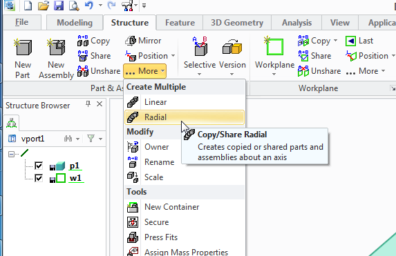
And by creating a big gear with a single tooth. then replicating it around an axis
Now I'll look at a third and final way of creating a spur gear, and show how this is also the way you need to make a helical gear, (with diagonal teeth) and a herringbone gear, (with herringbone -like little arrows teeth)
Even though this tutorial will show now to create all the gear types it's worth looking at the others, mostly because I'm only introducing the tools used once. so the lessons do build on top of each other, also, it's good to know more than one way of getting a part made.
We'll imagine the same scenario as the last post, that we have two axles 50mm apart and want two gears to link them.
The gears mesh together, so again we'll have the raise teeth of the gear protruding the 26mm radius, and the reciprocating grove in the gear at 24mm.
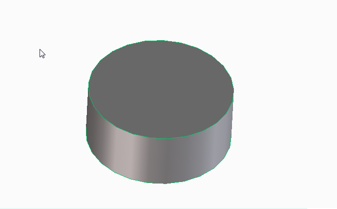
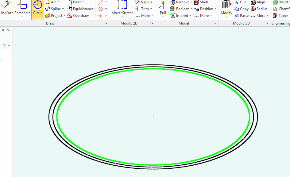
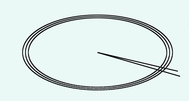
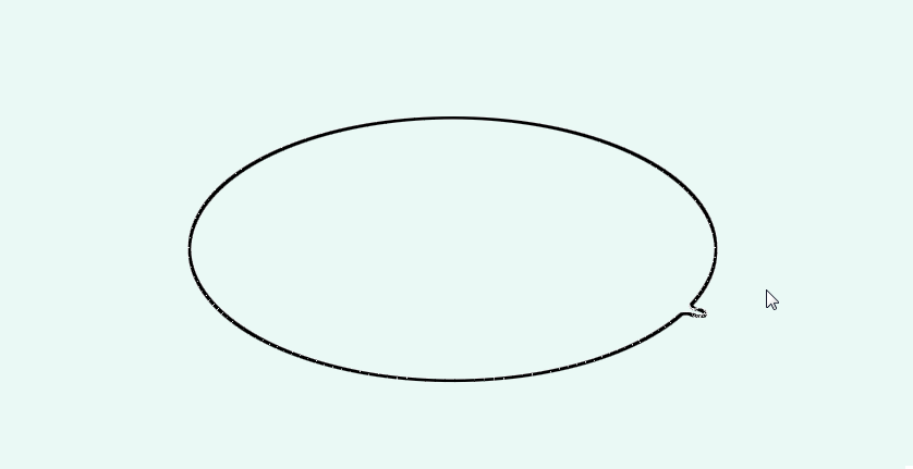
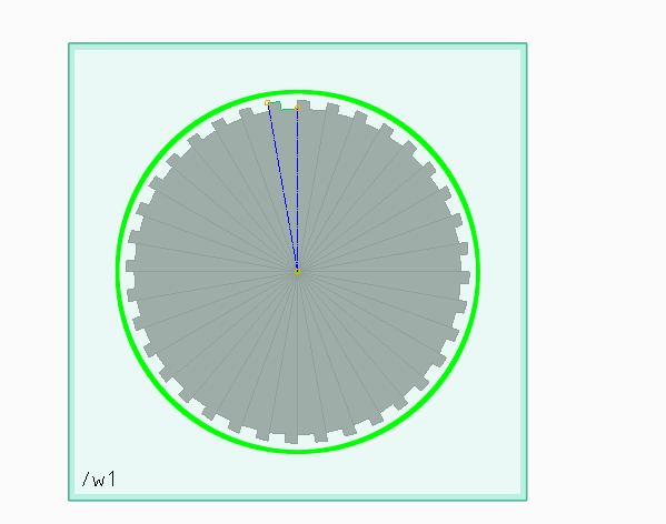
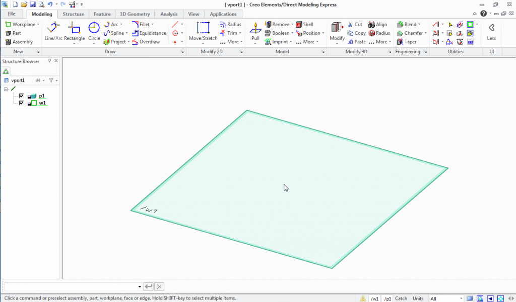
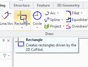
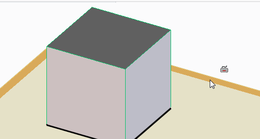
This time draw a circle that's 24mm.
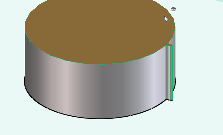
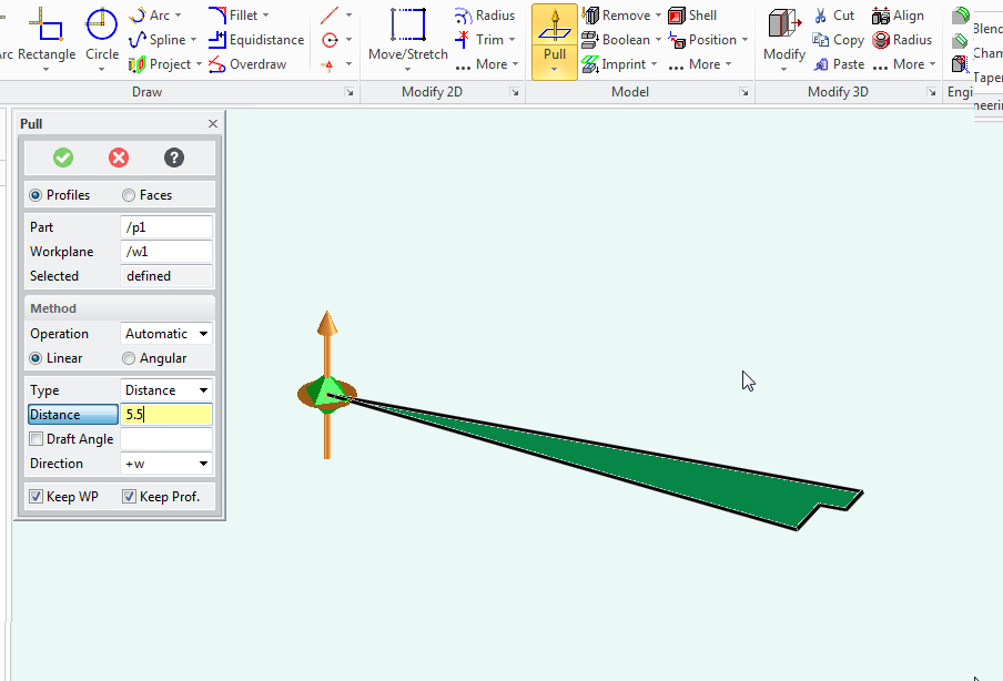
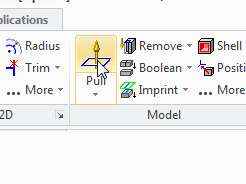
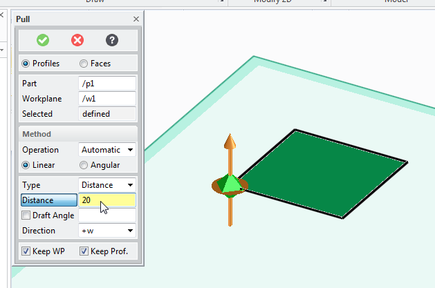
pull the circle into a cylinder 20mm tall.
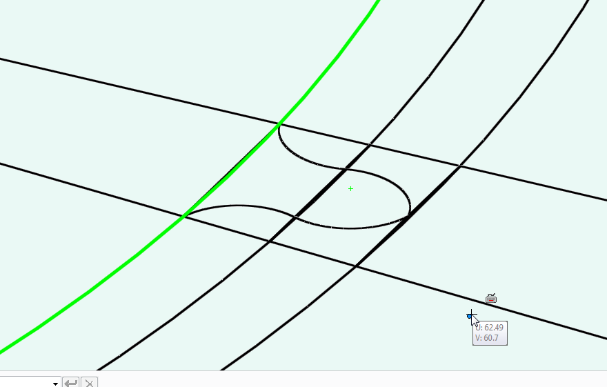
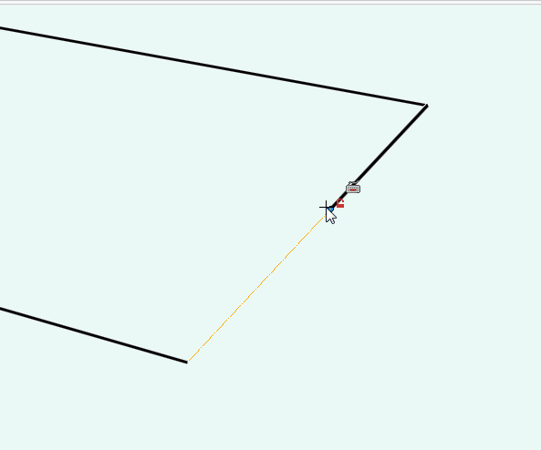
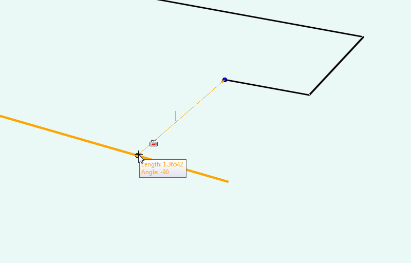
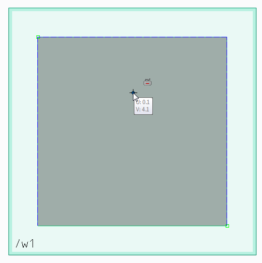
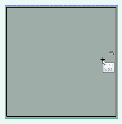
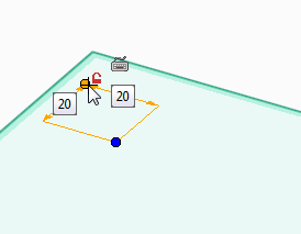
Now create a new work plane on that cylinder, draw guide lines for your tooth profile to be created, again at an angle of 5 degrees.
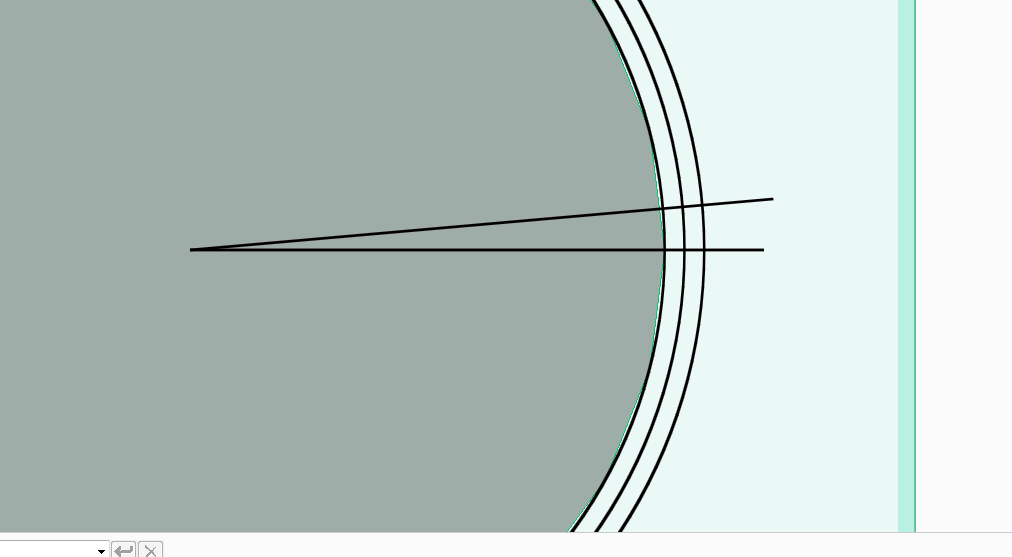
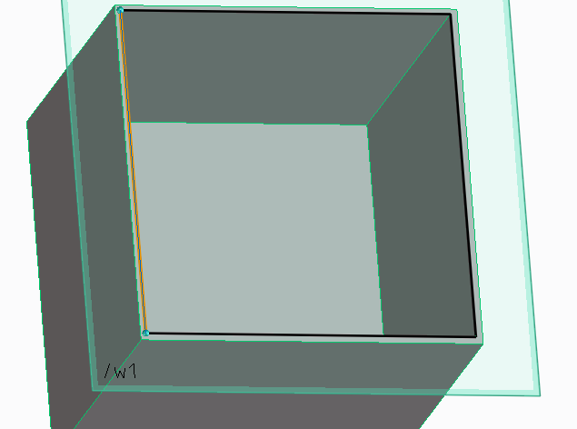
Once again draw a tooth profile onto the edge of the cylinder, your tooth crown should be 26mm from the centre.
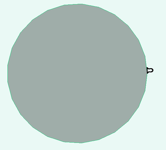
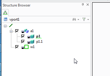
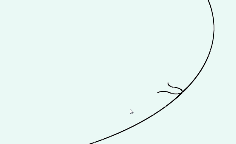
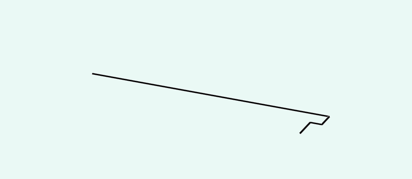
Delete your guidelines that you've drawn and you're left with a single tooth on a cylinder again.
But this time I'm going to make a helical gear.
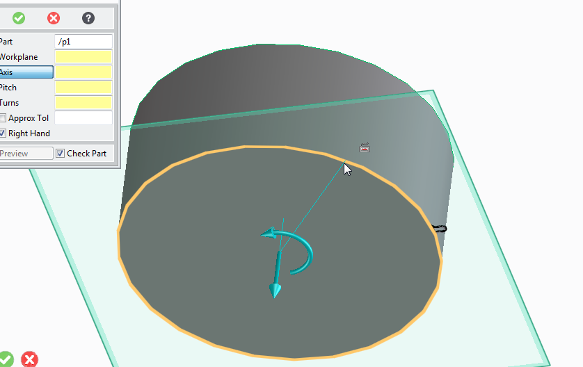
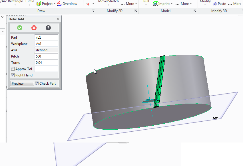
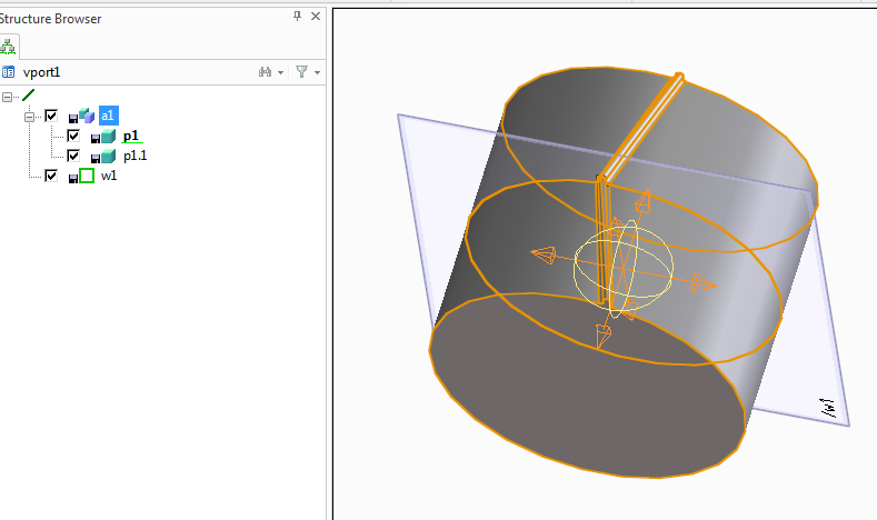
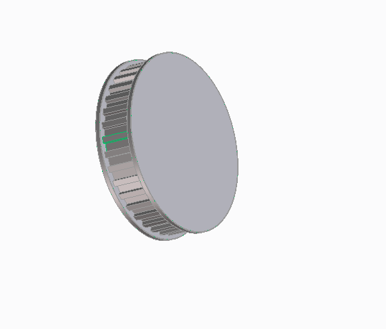
Select the helix add tool
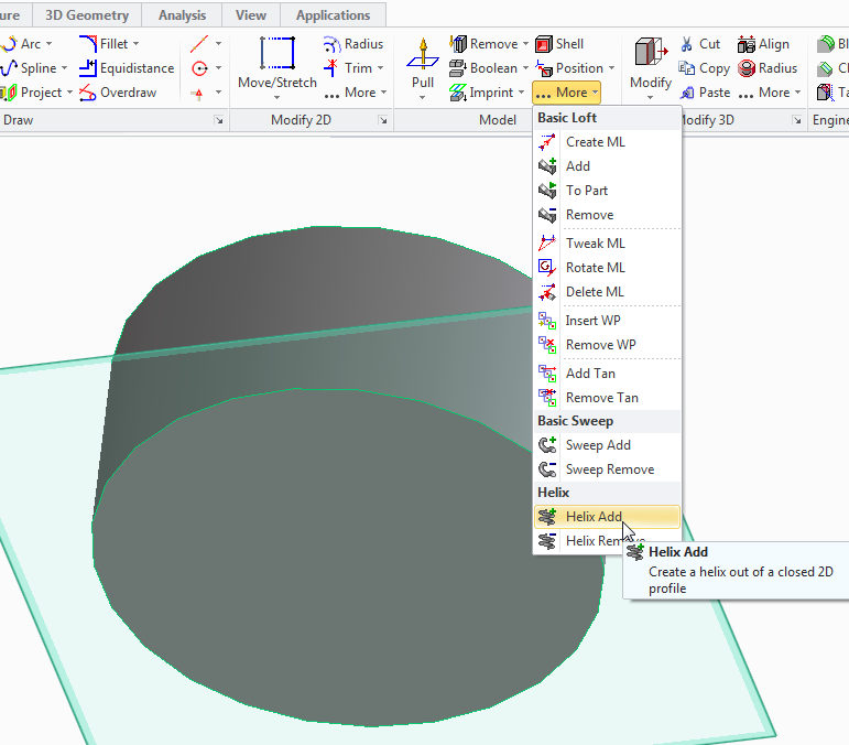
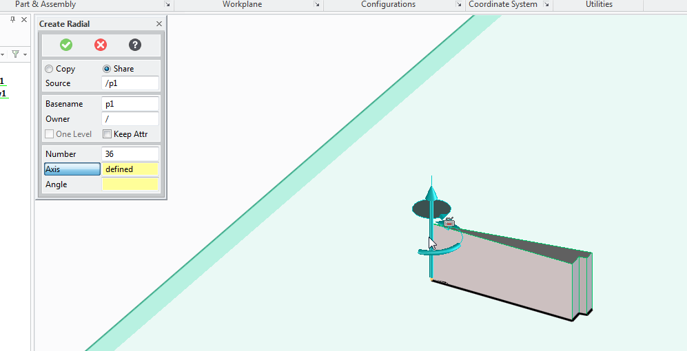
Select the axis as the centre of the cylinder part.
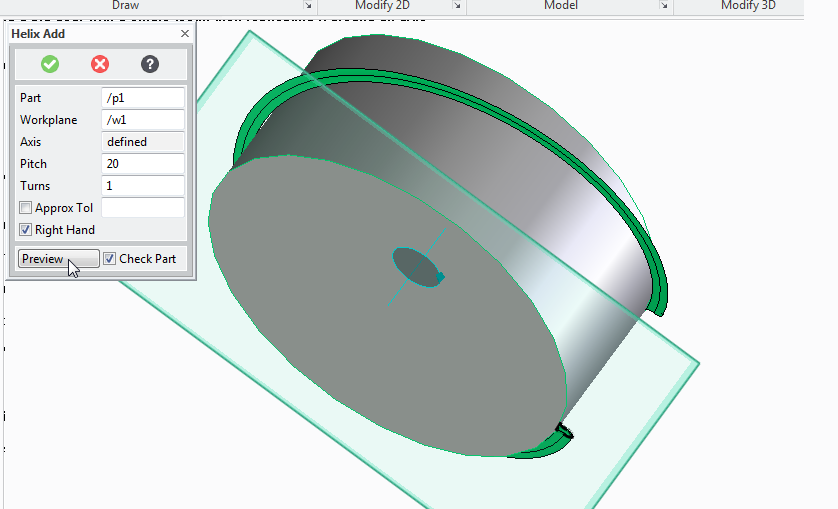
Our part is 20mm high, therefore if we select 20 for the pitch and 1 for the turn, we'll get a single complete turn of the tooth profile all the way around the part.
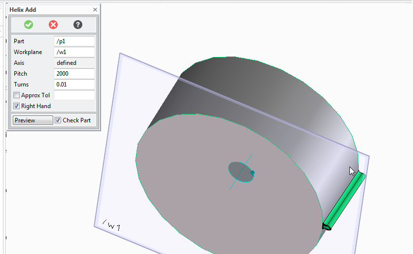
To progress 5 degrees around the part we need 5/360 turns (roughly 0.01)
and to keep the same pitch to turn ration (to make the tooth reach the top of the gear) we need the pitch to change to 20/0.01 = 2000
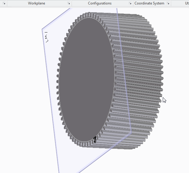
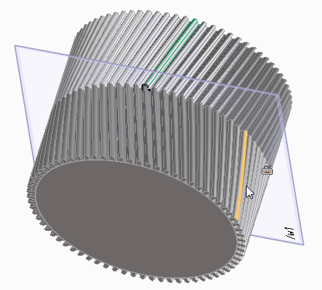
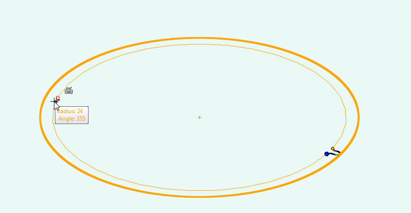
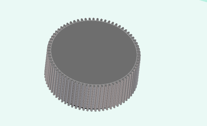
since each tooth takes up 5 degrees we'll mirror 72 times, at an angle of 5 degrees.
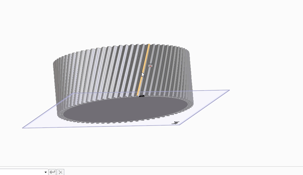
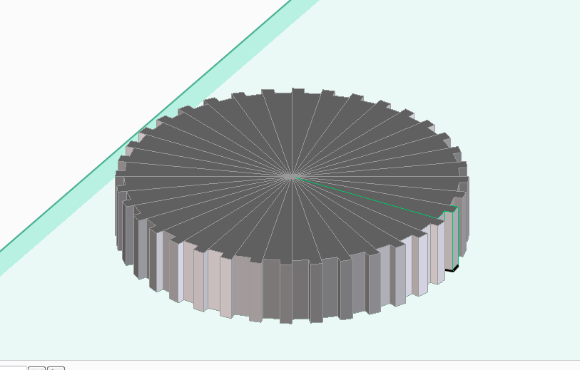
Giving us a helical gear.
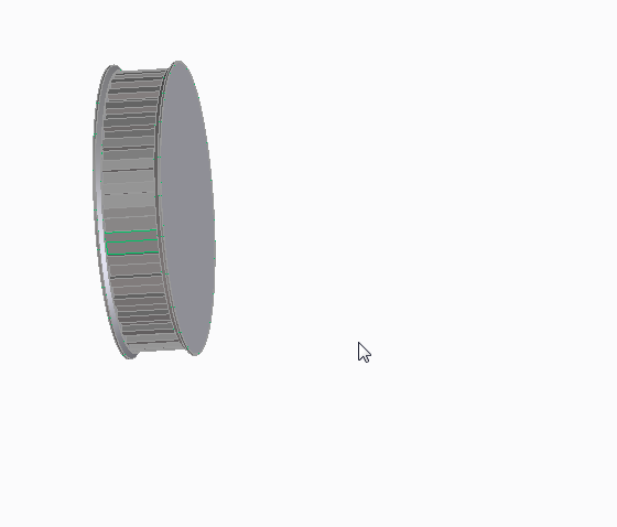
Now imagine that we want a steeper angle on those teeth.
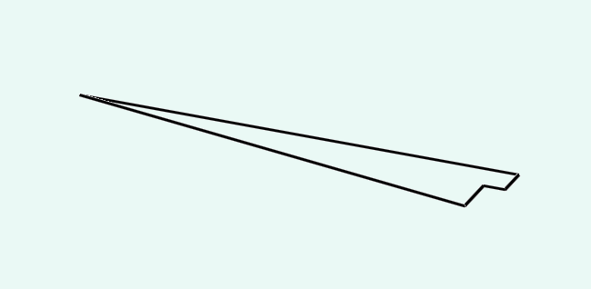
go back to the part where there is just the outline of a single tooth ready to be added as a helix.

we need figure our the turns first.
360/20 =~0.04
then we need to figure out the pitch,
20 (gear height) / 0.04 (turns) = 500

Once again, use the rotational mirror tool to make 72 teeth with an angle of 5 degrees about an axis that is the centre of the gear.
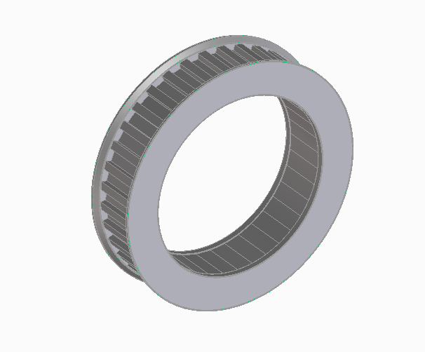
HerringBone
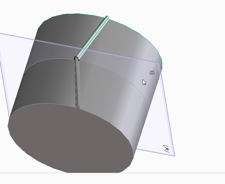
Alternatively.
Before mirroring the tooth rotationally, to create a herringbone gear mirror the tooth along the face first.
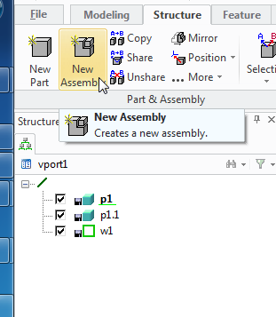
now you'll have noticed that mirroring creates a lot of individual parts. We're going to apply the rotational symmetry to the herringbone gear that we are creating, so we want to group the parts into a single assembally so that we only need to perform the mirror opperation once.


