Showing posts with label supplies. Show all posts

Wednesday, July 27, 2011

Craft Lessons: Wood finishes -French Polishing

There have been a flurry of electronics lessons recently, and I thought that it'd be nice to cover a craft subject again.

So, in this lesson I'm going to cover French polishing.
The reason that I'm writing this lesson now is that I've done a big project that involved French polishing, when I write that up I just want to be able to say, I French polished, and link to this lesson rather than write the whole method in the project write up.

Equipment
For this you're going to need;
>A lint free (preferably cotton) cloth, -lint free just means a cloth that doesn't have bits that come off.
>Some mineral based oil, (I used baby oil)
>Something to polish.
and last, but by no means least, Some French polish!

French Polish
There are two ways to get French polish.
Either, you need to buy shellac flakes, and some alcohol, then you need to dissolve the shellac flakes in alcohol, then store it in an air tight bottle, (so that the alcohol doesn't evaporate), you'll need to have some practise to find what quantities of shellac to dissolve in what quantity of alcohol.

The alcohol you need to use is either de-natured alcohol, or methylated spirit.
you use around a half gallon of spirit for 1 - 2 pounds of shellac.

What you need to do is measure out your shellac into a large pot, then add your spirit. Leave the mixture to sit, stirring occasionally until all the flakes have dissolved, you then need to filter the mixture to remove any stuff that's not shellac.

Or, option 2, buy a can marked French polish, that's already been mixed and filtered etc.

Which is what I do.



When I say that you want something to polish, make it something nice, because this polishing does take a lot of work!
also it only really works on natural woods, plywood at a push, but will not work on MDF, hardboard or chipboard or any other kind of particle board.

Making a rubber
Before you can start applying the polish, you need something to apply it with, you need something to rub the polish on with, and this is called a rubber.

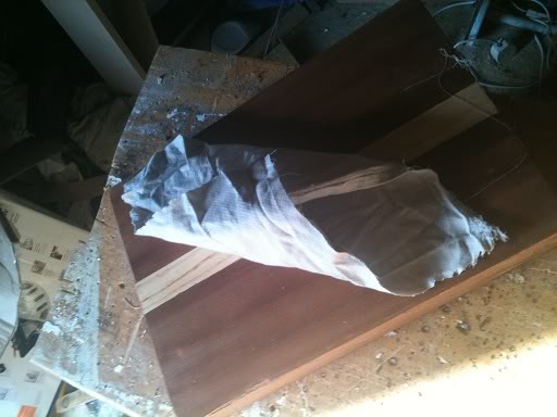
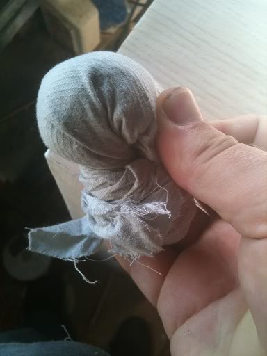
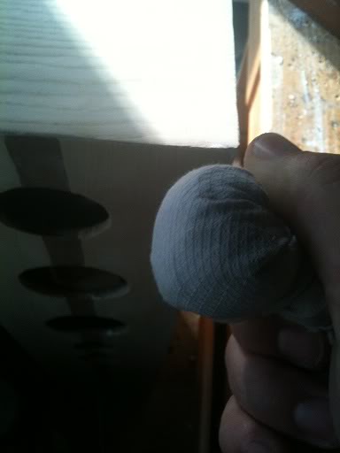
Basically, a rubber is a lint free cotton cloth, folded and twisted into a shape that gives a flat edge (called the sole), and inside of this there is a wad of material, (either more cotton, or cotton wool) that you apply your polish to to act as a reservoir for the polish.

Here is how to make one:

Take two squares of cotton, both about 12" square.
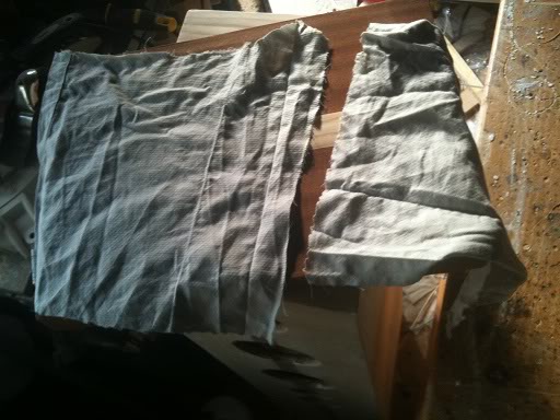


Lay one piece flat, and ball the other one up, and put it in the middle.
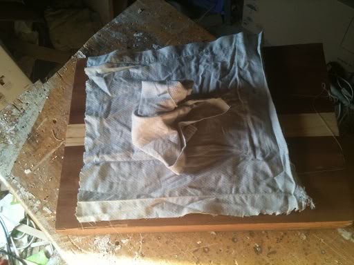

Now, loosely fold in the edges.
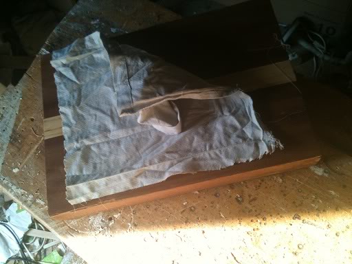


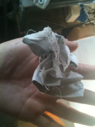
When all the edges are folded in, twist the corners together, pulling tight on the ball of material in the middle to make a firm yet spongy surface that is flat (ish), it should be spongy like a medium rare steak is spongy (when you press it, not eat it).
Charging your Rubber
Now you want to unfold it, and apply polish to your reservoir then bundle it all back up again.

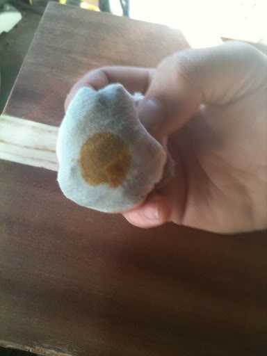
You want polish to be available in the sole of the rubber, but you don't want to pour in too much polish that the whole thing leaks uncontrollably, so pour a little polish into the wadding in the middle then press the rubber onto a surface to start to squeeze the polish through the material down to the sole of your rubber, if you find that there is not enough polish inside your pad, you can always add more. -easier to add more than take any way.
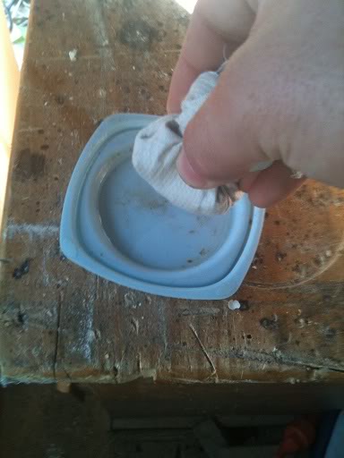
Shellac is quite sticky, and you'll find that as you apply the polish that the rubber doesn't exactly snag, but does become difficult to move across the surface of your work piece, this is where the mineral oil comes in. you should smear some oil onto the sole of the rubber, to do this I just put a few drops onto the lid of the container that I keep all the polishing cloths in and then just dip the rubber into the drops that are on the lid.
Polishing
At this point you have your rubber, you have it charged up with polish, and a little oil to help it glide, now you need to start polishing.

To start polishing you need your work piece to be held steady, if you're working on something that's flat, then just put it on a table, you don't need to clamp it down, if you're doing something more complex, then you might need to hold the work in one hand, whilst polishing with the other.

Now, I learned to polish by readying guides on-line and watching videos, so it is possible to learn that way. But it's sometimes confusing when getting started as to know what to do.
Some guides will tell you to start with a skimming motion, others suggest a circular motion to start and call this grain filling.

You can do what works for you, either applying polish and moving in small circles, to fill the grain, or using long straight swishing motions. I prefer the latter, it takes more time to start, but I find the finish to be superior, and find that I don't need to sand the surface between coats to remove blotches as there just are no blotches.

So, this is what works for me, If you find a different method works for you better write it down in your own blog/site, feel free to leave a link to it in the comments.

Starting to polish
First you need to have prepared your wood, by that I mean it's clean, it's been sanded, it's smooth it's been dusted to remove any saw dust.
Now you need to imagine an old grandfather clock with a pendulum,
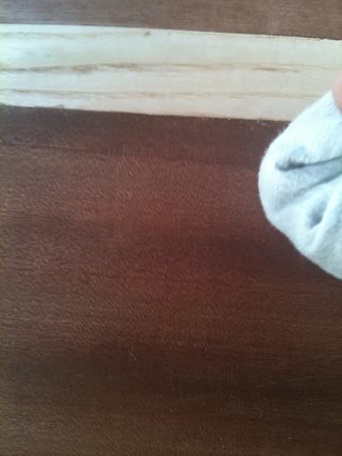
you are going to swing the rubber at the work piece, with about the same pace as a clock pendulum swings, start from slightly above one side of the work piece, swing down and across the wood following the grain of the wood, then come smoothly off the end.
You should see a smear of the French polish on the wood. but this wet looking smear is mostly spirit, and it will evaporate, leaving just the tiniest coating of shellac.

The strip of white wood is about 1 1/4" to give you an idea of the scale of things here, the trail of polish is about 4 - 6" long and the total arc (from where my hand started to where it ended up must have been about a foot,) as I said, go at the same pace as a clock, so that sweep takes about a second, (you can apply polish in both directions too.)

Proceed to do this all over the wood, so that there is a really thin coating on the wood, then go over it again. Do not try to build up too much coating at this stage.

Drying and hardening
At this point the hard shellac finish is on your work drying, but as the spirit/solvent is still evaporating out of the polish it's still quite soft, if you try to build up the coat too much and too soon you actually pretty much end up wiping off the polish that you've just put on.

So at this point put the rubber into a plastic pot, that seals (to stop it drying out), and go have a cup of tea or coffee, come back in 30 minutes and repeat the polishing in the same long streak pendulum motion.

More drying and hardening
After you've applied this second round of the step one steps you should have about 4 microscopically thin coats of shellac on your work piece, at this point it should have a dull sheen, but won't have a high gloss shine like a piece of fine antique furniture.

At this point you should leave the polish to dry overnight.

Grain filled
That first stage of polishing was filling the grain of the wood, now that should have been done you can move onto a more random polishing technique, moving the rubber in small circles, and figures of 8 across the work piece, again, building up the polish little by little, allowing it to dry, coming back and applying another coat, then leaving it to dry.

If you start on a Monday and apply a couple of coats of polish each evening, allowing those coats to dry to the next day, by about Thursday this is what you should have accomplished.

(I didn't polish the corner at all so that you could see the difference between polished and unpolished wood).

And by the following Monday
you should see this:
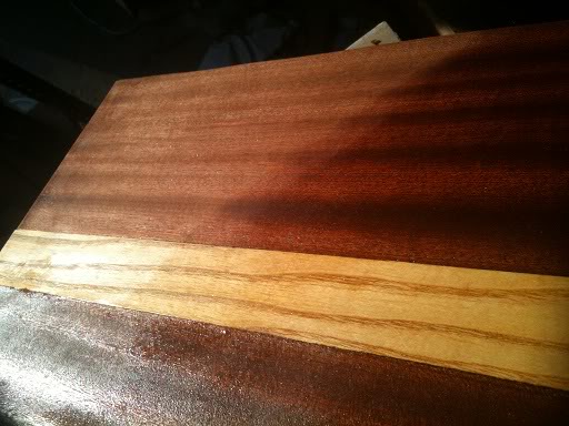
Again the top corner isn't polished at all, the other half from the picture taken on Thursday received no more polish, the bottom half (that's so shiny it's difficult to photograph, has a full week of polish.

It sounds like a lot of hassle, but remember this is a small piece so it's actually just half an hour a day really. (actually this small piece was a part of a much larger project, so it did take quite a lot of time, I didn't polish everyday, so some coats cured for longer than others).

Comparing the polished wood to unpolished wood is below, (I stood in the way of the light so that it didn't reflect so much.
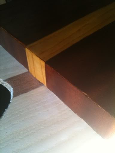
The finish
Your work should now have a shine a sheen and a deep lustre to it.
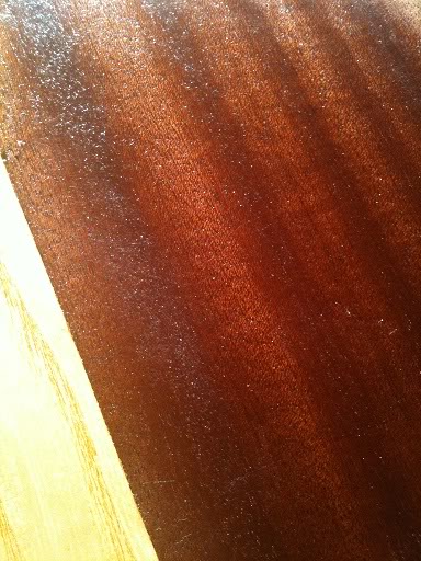
French polishing gives a durable finish, it's water proof and quite tough (after all the original spirit is properly evaporated), however it is still solvent in alcohol, so if you're thinking of making a bar, French polish probably isn't the most appropriate finish!

The polish that I used was an Amber polish, this means that the shellac flakes that made it were amber in colour, and as you can see, it has stained the wood. Shellac comes in a variety of hues, to if you're mixing your own, be sure to mix enough to do the job in one batch, don't assume that you'll be able to get the exact same mix again later.

If you're buying from a shop, be sure to make sure that if you have to buy more than one can, that you buy the same colour polish!

Monday, July 18, 2011

Converted ATX Power supply

Recently you could be forgiven for thinking that this had changed from the idiots guide to puttin' shit together, to the opinionated guide to how you should have done your projects, or the idiots musings and bad teachings.

I'm definitely going to continue the tutorials because it's actually quite fun to write them, and I'm finding that as I go over the ground again, I'm re-remembering some stuff that I'd completely forgotten about. But this post is right back to the core of why I even started this blog, and that's to share something that I've made.

Firstly,


There's your warning, but if you can't figure out for yourself that there is an element in danger in modifying anything that plugs directly into the wall then you should probably stop reading now and go elsewhere.

Theory
The theory for this is so simple, I have a power supply (a computer power supply), and I want to turn it into a bench power supply, so I pretty much just need to cut off the wires that aren't needed, and attach the appropriate plugs to the wires that are need!

How it works
The computer power supply maker has done all the hard design parts for me it's a switch mode power supply, mains supply and as it's switching faster, the transmission of the energy inside the ferrite core, basically that means that inside the power supply is switching on and off at a very high frequency, this is much faster than your 50Hz s of the transformers inside is more efficient, more efficient means that you're not generating as much heat, and not as much energy is wasted as heat.
A traditional power supply, would require an absolutely huge iron core surrounded by pounds of wire to be able to get the same kind of output power that a switch mode power supply (SMPS) gets.

Why it's important
The high frequency is important as that's what allows the supply to be so efficient. The fact that someone else made it is important because it means that you can make this supply inside a single afternoon.

If I was designing my own SMPS, I'd probably need to research for at least days, if not weeks, I'd need to source components. Create circuits to sense the output voltage and adjust the input if necessary, it'd be a lot of work, yet I can turn an old supply from a broken PC into a perfectly reasonable bench supply in a matter of hours.

Simple experiment
Before even breaking out the screw drivers, or plug in the soldering iron. I took a look at the computer power supply unit.

There is a big plug with either 20, or 24 pins on it. inside all these pins there will be a single green wire, with a black wire either side of it.

Using a small bit of wire I pushed it into the pin connected to the green pin, and one of the black pins from either side. The fans spun into life, and voltage could be measured at other pins.

You can just use the supply like this with no further modification, inserting your bit of wire to turn it on, removing your bit of wire to turn it off.

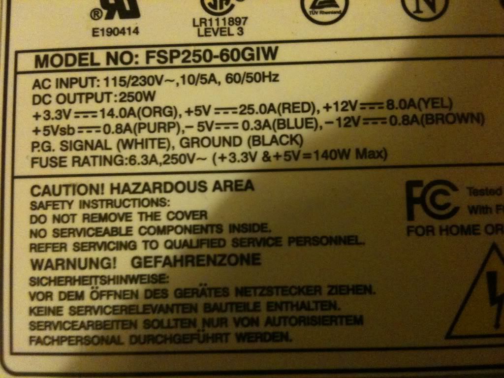
On the side of the case there was a table that telling me what colour wire carries what voltage, and what the limits of the current capabilities are for each voltage. this made it a whole load easier that searching for a pin out on-line for the ATX plug to know what pin was what.


Converting a power supply

Parts and tools required
>an old computer power supply
>a screw driver
>some terminal posts
>Wire cutters
>A switch (push to make locking switch)
>A LED
>A 10mm drill bit
>A drill
>A 6mmDrill bit
>Insulated screw terminals -these are not important, you may chose to leave these out
>A 470Ohm resistor
>A soldering Iron
>Solder (flux core)

Taking it all apart

The first thing that I did was take off the lid of the box, The fan is connected directly to the board with no plug to remove it, so I removed the fan from the case lid.
Modifying the part
Lets deal with the lid first,
I knew that in the lid i'd need to put a switch (basically in place of the wire that I had before),
You might want (I did) a nice LED to tell you that the supply is on.
I also wanted to put plugs that to connect the wires to in the lid.

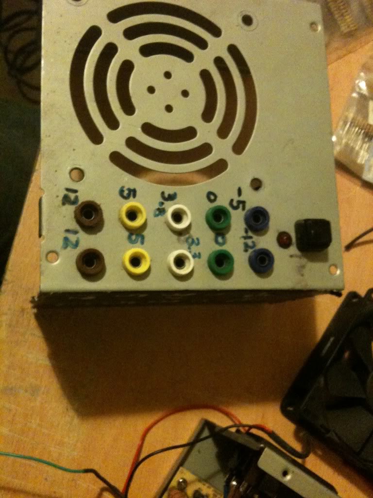
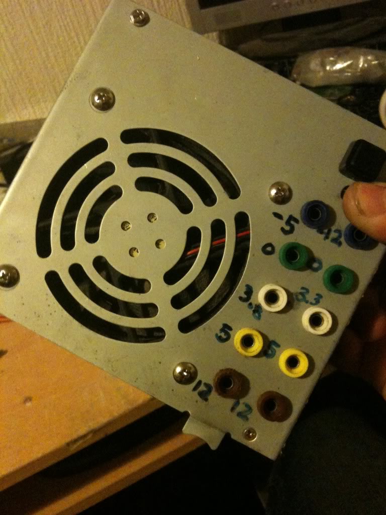
I chose to mount my plugs in two columns, (2 x 12v, 2x 5v, 2x3.3v and 2x0v) as these are the voltages that I'll use the most often, then I have one plug for -5 and -12, as I'll use these less often.
As it happens, banana plugs are usually stackable, so you won't really loose an functionality just using a single row of connectors.

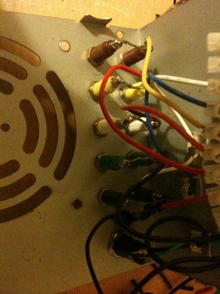
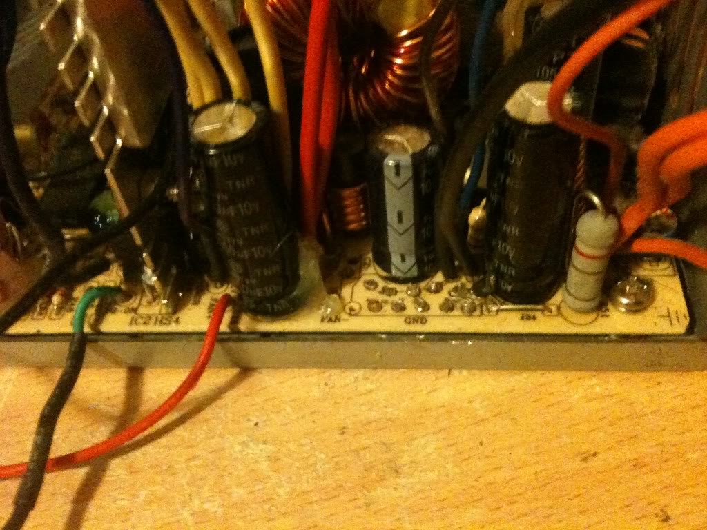
When I looked on the inside, of the power supply, I saw that there were basically two sides, one side has big heat sinks in it, and the mains plugs next to it, the other side is fairly low profile leaving the top of the case empty. I decided that I'd like to keep my plugs away from the side with exposed mains connectors that the bottom of the terminals might hit, and away from the heat sinks for the same reason

I marked out the lid and drill the holes for all the part to go into.
Then installed the plugs, LED and switch (I used a simple black collar for the LED it's called a panel mount and costs about a penny. -you could leave the LED out completely).


I just used a marker pen to write the voltages on the top of my supply, you might use nothing relying on the colour of the plugs to tell you the supply voltage, perhaps you might like to try etching or engraving, or using a label printer, I don't really care, pen works for me, and that's good enough.

Next as I have two plugs for one voltage, I connected these plugs, using a piece of wire running between them.

I also want to add a 470Ohm resistor to one leg of the LED (this is to limit the current that goes into the resistor).

(That'll connect to the 5v rail 5/470 = 0.01A or 10mA, enough to make the LED glow, you might like a bigger or smaller resistor depending on the needs of your LED, it's also 1/20th of a watt, so a simple small 1/8th watt resistor will be fine.)

I soldered leads to everything ready to connect to the terminal block connector.


Finally I was able to stop working on the lid and move onto modifying the actual PSU.

One thing that you'll notice is that the wires are colour coded depending on their job. And there are a LOT of wires that are the same colour, in the supply I used there were about 10 black wires, all 0v, all from the same pad on the PCB!
I needed 3 black wires, could have got away with 1, but three was good (one for the power button, 1 for the LED and 1 for the output plug).
I really only needed 1 -12 wire, only 1 -5 wire, only 1 +12 wire. and two +5v wires (one for the plug, and one for the LED.

You do only need 1 3.3v wires, but in addition to the thicker wires you must keep the very thin orange wire, this is the sense wire that determines what voltage is being generated, and regulates the supply, without this wire your supply can float.

Anyway, I cut away the wires that I didn't need (that I could get to)


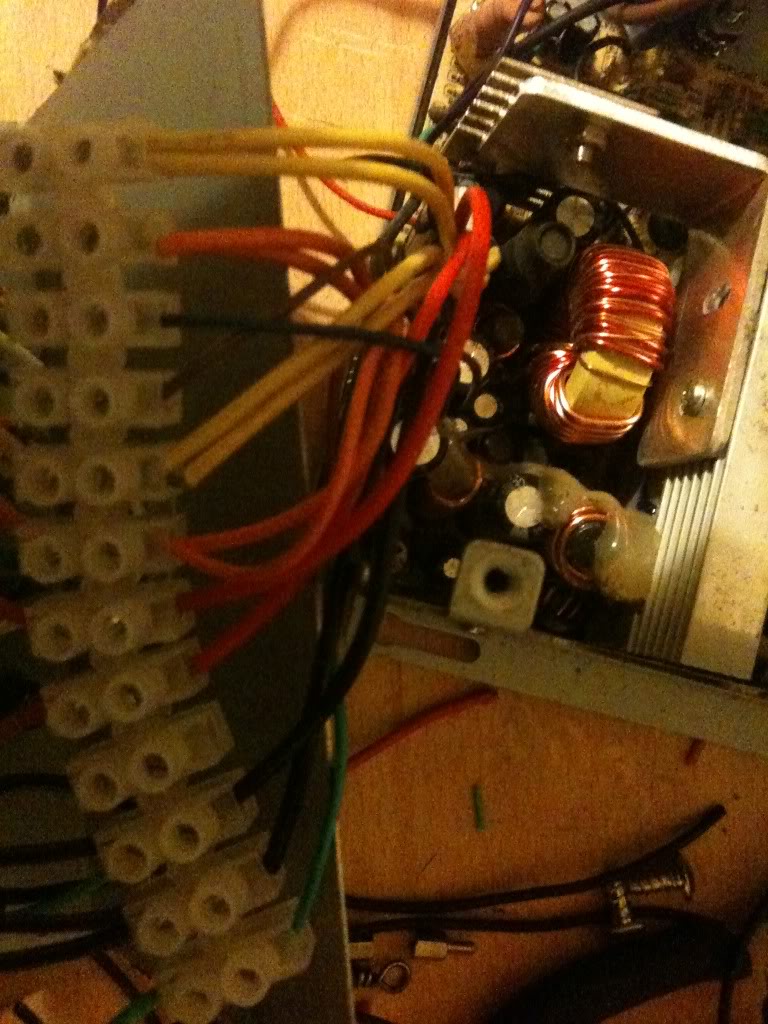
I couldn't get to cut the red or yellow wires, so I'm going to tie these off later in some spare terminals on the connector.

Putting is all together
So I'm now in a position where I've thinned out all the wires that I don't need, and I've trimmed all the wires that I do need to about four or five inches long so that I have plenty to work with.

Now I striped back the wires, and attached them to the terminal block.

It doesn't matter what order you make the connections in, just that black wires connect to ground, terminals, and the negative side of your LED, also that there is a black wire attached to one terminal of your switch.

You want the green wire to attach to the other leg of your switch, and a red wire to attach to the LED for your "on indicator".
Yellow wires are alwyas 12v, Orange is always 3.3v, Red is always 5v, minus five and minus 12 however do not appear to have a set colour scheme, and as such may vary.

The colours were written on the outside of the supply I used, you may have to poke around with a multimeter. or look for an ATX pinout and just select the correct wire from the plug.


Once all the wires were connected I attached the fan to the top of the case again, and put the top of the case onto the bottom. as I said earlier, make sure that the bottom of your sockets do not touch the metal bits inside. Also make sure that no wires are touching the heat sink where the insulation could melt, and that no wires or the large terminal block is getting in the way of the fan.


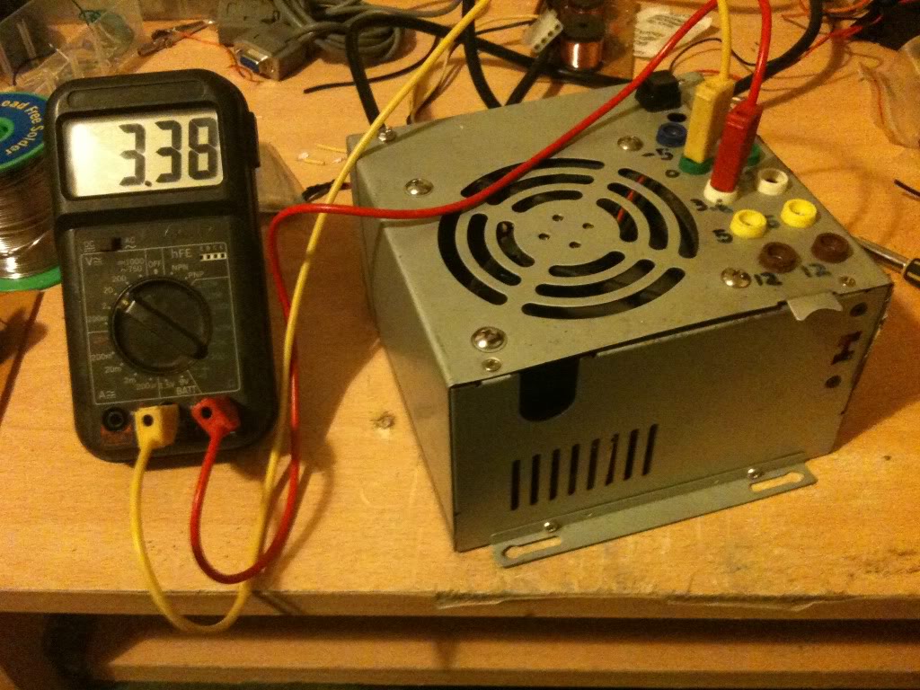
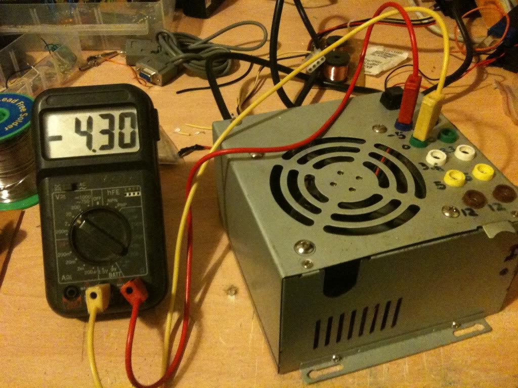
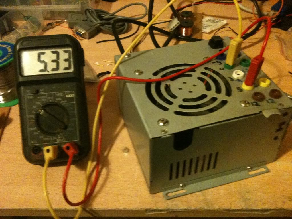
Now I measured The output voltages using a multimeter.


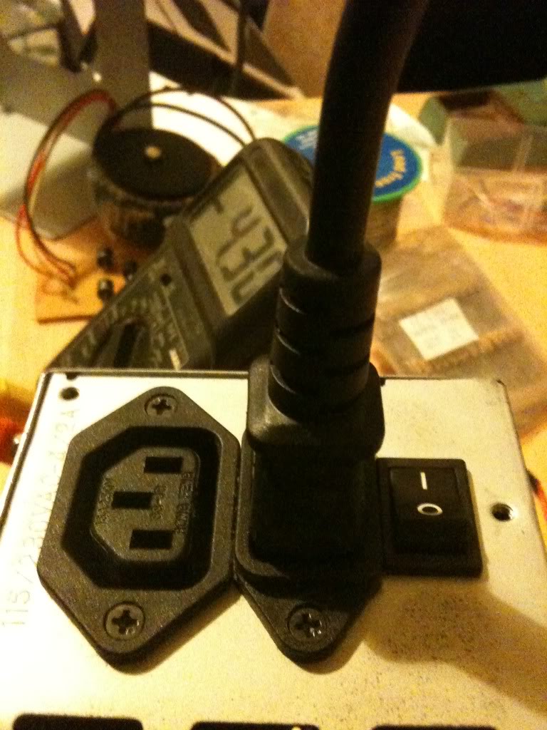
Since I'm always seeming to run out of power outlets, I chose a power supply that lets me get mains power out as well so I can daisy chain equipment together.


Costs
This is not the cheapest project in the world, but it is cheaper than buying a power supply with the same amount of usable outputs, regardless of whether those outputs are of a fixed voltage, or five variable voltages. I had everything either in my parts box/junk bin so this really cost me nothing.

There are 10 4mm sockets, these are 20 pence each from Rapid Electronics
http://www.rapidonline.com/Cables-Connectors/Connectors-Single-Pole/4mm-Connectors/4mm-Sockets/63893
(total cost £2)
The Square Single pole single throw switch cost 36 pence.
http://www.rapidonline.com/Electronic-Components/Switches/Push-Button-Switches/Square-push-switches-1A/30275
(toal cost £2.36)
LEDs cost around 9 pence (or less) (when you buy them in bulk).
here's one for 6 pence http://www.rapidonline.com/Electronic-Components/Optoelectronics/5mm-LEDs/Low-current-5mm-LEDs/29336
(total cost £2.45)
Resistors cost even less than this when bought in quantity.
http://www.rapidonline.com/Electronic-Components/Resistors-Potentiometer/Carbon-Film-Resistors/CR12-0.125W-Carbon-film-resistors/65192

65 pence for 100, seriesly people stop shopping at Maplin/Radioshack

Rapid cost 65 pence for 100, (or ~ half a penny per resistor).
Maplin cost 25pence per single resistor. (50 times more expensive).
http://www.maplin.co.uk/components/resistors/metal-film
If your project requires 3 resistors, it's cheaper to order on-line and have 97 spare/left over!

(total cost £3.10)

Now comes the expensive part, if you don't have a spare power supply laying about, (and don't have the resourcefulness to find one for free), then you'll have to buy one. for the princely sum of £7.86!
http://www.ebuyer.com/product/20083

Total cost £10.96! Much cheaper than any other power supply that I know of. in fact we're really knocking on the cost of a single voltage wallwart cost here, which has a lower power capacity and only 1 voltage output (which may or may not be adjustable!)

Alternatives, -and Why I didn't use them
This is something I started when I wrote up the red light torch, there are so many ways to crack an egg. So my way is not the only way, just the way that I chose on that day.

Spring terminals:
Spring terminals are useful if you're doing a lot of breadboard work, without a breadboard that has power terminals, but practically everything I've got is set-up for 4mm banana plugs, my multimeter, the power terminals on my breadboards, crocodile clips connect to 4mm plugs. Spring terminals may well have been cheaper, and indeed wouldn't require me to buy 4mm plugs to go with them, but since I'm set-up for using 4mm plugs it makes sense to use them

Binding posts:
Yes, these are just like 4mm sockets, except that you can also attach bare wires and screw them down, making them a whole heap more versatile. The only reason that I didn't use these is that I didn't have any in my parts box, and I did this project one evening after the shops were closed.

Directly soldering the leads:
I could have missed out the terminal block connector, and indeed the first time I made this supply I did. without that chunky connector however there are two things.

The wires that you can't cut off at the board end up loose in the case, you can wrap them in tape, but it's a bit messier than being able to put them in a spare space on the terminal block.

The first time I built this supply I soldered straight to the plugs, I broke that supply, and it was quite a PITA to remove all the old connections to put new connections on it. if I ever need to change the actual board again I can just take the case lid as I did this time and bolt it to a new supply just cutting and stripping the few wires that I need to use.

Sandbar resistor
Instead of just a locking switch on the green "power on" line, you should use a resistor on the 5v line to apply a load to the circuit that'd sense that it's on. That's the "proper" way of doing it.
I didn't do it like this because...
1> The sandbar resistor has to be a high power resistor, tied to the case for cooling, this seemed like it's take a lot of space inside the already cramped case, and is a part that's going to increase the idle power consumption of the power supply.
2> My supply works without it, so I'm not too worried really.

External plug-set with ATX/Molex connections
In the theory section you saw that it's possible to turn the supply on with nothing more than a piece of wire, I could have kept the supply as is, put molex connections on my projects, of I could have just made a board with my 4mm sockets arranged just as they are where the power supply just plugged straight into it.

The good side of this is that I wouldn't have had to open the case at all. So if you have a skittish partner or parents then you may wish to go this route. (If they aren't happy for you to plug things in after you're taken them apart and soldered bits to them!)

On the other hand, I think that you'll end up with something a lot messier.

Friday, July 15, 2011

Electronics Lessons: The Diode

Diodes come in a lot of different formats, not only high or low voltage, but for specific purposes, I would try and make a list here of all the different types, but I know that I'd miss at least one!

What I want to concentrate on here is a small silicon diode, A say small, as diodes can be bigger and perhaps have different electrical characteristics. diodes can also be made of different things, which again gives them different characteristics.

What is a diode
In the simplest sense a diode is a one way valve for electricity. It'll let voltage flow one way. but not the other way.

So diodes are quite useful things to put into circuits as a reverse polarity protection. protecting sensative components where they can't handle negative voltages, or being connected backwards.

Symbol
The symbol for a diode looks like an arrow, the arrow shows the way that the electricity flows, at the head of the arrow is a bar, this shows where the electricity is blocked.

So approach from the left you see an arrow sort of saying this way through, approach from the right you see a big bar saying no entry.

The left side is the positive leg, the right side is the negative leg.


Diode use
The easiest way to show what a diode is would be to look at a very simple circuit.

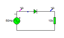
At the left hand side of the circuit there is a sine wave generator, this generates positive and negative signals in a sine wave.

At the right hand side of the circuit is a resistive load, in the middle there is a diode.

There are two probes connectted to the circuit that show you what the wave on that circuit looks like.

Here is the circuit.


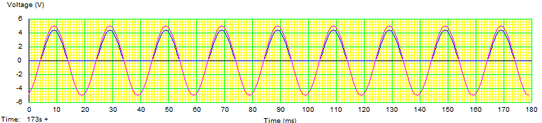
the graph below shows the voltage that you'd see if you'd hooked up an oscilloscope to that circuit at the places shown.


you can see that the original waveform is the pink line, it goes both up and down in a sine wave formation.
The blue line is after the diode, you can see that it's letting through the positive half of the sine wave, but the negative half is being blocked.

This circuit is called a half wave rectifier.

Another thing that you might notice is that the blue line isn't quite as big as the pink line. some voltage appears to have disappeared.

Forward bias voltage drop
That's a bit of a mouthful. so lets break it down.

Forward bias simply means it's connected so that electricity flows through it forward.

The voltage drop of a small silicon diode is usually around 0.6 - 0.8V (say 0.7) but the larger the diode the larger the voltage drop. So a large Silicone diode like you might find in a power supply rated for a thousand million volts might have a voltage drop of 1 - 1.5V

Take a look here http://en.wikipedia.org/wiki/Line_level#Nominal_levels

If you're dealing with line level audio signals a 1.5v drop passing through a diode is going to eat up much of the signal!

The blue line is a little lower than the pink line because some voltage is lost/used up inside the diode.

You may also hear the forward voltage drop referred to as forward bias breakdown voltage, as it's the voltage required in the forward bias to start breaking the bonds inside the silicone to allow electrons to flow.

Reverse breakdown voltage
To be honest, I hadn't planned to include this, however, I've got a bit of a point to including it...
Diodes don't conduct when connected backwards right? Well... that's nearly right, at a certain point when there is a large amount of voltage, the internal structure of the diode will breakdown, and it will start conducting both ways. and the component is dead (I'm not talking about Zener diodes, I'll cover those later).

The point to including it was to say that it's important to chose the correct component for the job that you're doing.

Components can be selected on cost and function, sometimes you have to compromise the function to keep inside the cost, sometimes you have to compromise the cost (spend more) so that you can get the correct function. There is no one component fits all approach to electronics.

If you have 1 diode that you always use, then the chances are that it's not the right diode.
as I said earlier, 1000v diodes just aren't going to work as signal diodes in sensitive equipment, but at the same time small signal diodes aren't going to be any good for creating power supplies.

Selecting Diodes
Selecting resistors was a bit obvious, you picked the right resistivity, and the right power handling then you were more or less done. (it can be more complicated than that, but at the basic level that's all there is to it).

With a diode, it's just as simple, but you don't get it divided into nice easy to spot sizes, or colour codes written on the casing.

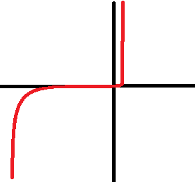
What you do get is a data sheet, and somewhere in that data sheet is a chart that looks a bit like this:

Now I've deliberately left off the values, look at the chart,
In the middle is a standard set of axis, X and Y at right angles to each other.

The middle where the lines meet is 0,
The X axis represents voltage;
From the middle to the right it's positive.
From the middle to the left it's negative.

The Y axis represents the current flowing through the diode.

lets go from the middle towards the right first, you'll see that its only a short distance (0.6 - 0.8 volts in the case of a small signal diode) until the diode "turns on" and allows the current to flow, increasing the voltage past this point doesn't really make a different. (until you exceed another value that you'll find in the data sheet call maximum voltage, or Vmax -at which pooint the component fails).

Going from the middle reading towards the left, you'll see it's quite a big distance that the voltage has to travel before reverse breakdown voltage is reached, when the component fails and conducts both ways.

Now, for a big 1000v rated diode, (that's 1000v Vmax) it'll be 1 - 2 volts forward voltage to turn on, and perhaps -800v to fail when connected backwards.

So can you use this diode to build a power supply (-240 - 0 - +240)? yes
should you use this to construct a circuit where voltages as low as 1.5v are used? no, because it won't conduct at that lower voltage.

For a small signal diode, that turn on voltage might be 0.5v (with a Vmax or 50v), and a reverse breakdown voltage of 30v.
can you use this voltage inside a tiny small signal circuit? yes, it's perfect!

Can you use it in a power supply? definitely not! it can't handle the reverse bias (so won't even act like a diode), it can't handle the forward bias either. as soon as you flip the switch you'd toast this little diode...

The moral of the story is read the data sheets and select your components according to what you want to do with them.

Monday, July 04, 2011

The Workbench/shop stock lists. Electronics (Beginners list)

I'm going to make a list of what I think the best starter work bench for electronics should contain. This list will be costed, -there's nothing worse than seeing a list of really useful tools then realising that you need to be a millionaire, (or be ninety and have been collecting tools your whole life) to have these things.

My "ethos" when making stuff is to make good stuff made well made cheaply.
by cheaply I don't necessarily mean that everything will cost pennies to make, indeed some things are very expensive to make -yet still cheaper than buying off the shelf. this applies to products and tools/equipment.

However, if I can buy off the shelf, and get a cheaper and better product than what I can make, then I'll probably buy off the shelf.


I'll be producing a few of these lists, because I don't think woodworking tools fit into the electronics tools list, nor do metal working tools, but if you are interested in making finished products, not just testing stuff out on a dev board, then you're going to need some tools and some skills to make a final project.

In accordance with an old hack a day post http://hackaday.com/2008/01/20/hackit-your-ultimate-hacking-workbench/ asking people to build up a work bench for $600 or less...

Well being as I'm from the UK, and that was from 2008. I'm going to say £600, (that allows me to not have to convert all the values, and allows for inflation). but I won't be spending all of that in this post. that's the complete bench costs, my bench needs tools for creating finished products. so I'll going to try and build the whole workshop for that price.

I'm also going to try to order the list in a getting your feet wet type arrangement, -so this will be the stuff that you might want to just pick up to be able to see if you even like making stuff for yourself.
so.... Here goes.

Electronics (Beginners list)
Multi-meter, -I don't recommend getting the cheapest, on the other hand I don't recommend getting the most expensive. (in the same way as my view on power tools went, professionals buy De Walt drills because the absolutely need them day in, day out), professionals by Fluke because they need them, day in, day out they are built to work in the shittiest of shit conditions, day in day out, they are drop proof, shock proof waterproof, dust proof and humidity proof.... my opinion is: "if you're a hobbyist, buy hobbyist tools".

For an absolute beginner, look for one that measures voltage, current and resistance. lots of meters will also have a transistor tester, and a continuity meter. More modern meters I've noticed recently, are including inductance, capacitance, temperature and even humidity and light meters as well as the standard volts/amps/resistance meters.

For the absolute beginner, ignore the fancy toys. buy basic, spend £10 - £20. if you need more functionality later then buy a bigger fancier meter later, you can keep your beginner meter laying around for emergencies, or when you want to work on the car and don't want your £200 meter getting dirty.

We'll call the price £20. (total so far £20).

Soldering Iron
I have a huge problem with people telling newcomers that they must get the latest greatest soldering station, with solder pots, and temperature control, and hot air reworking and all the other fancy gadgets. soldering stations of that calibre fall well into the professional end of the spectrum, and cost like they do as well.
http://www.rapidonline.com/Tools-Fasteners-Production-Equipment/Soldering-Equipment/Soldering-Stations/Weller-WSD81-80W-digital-temperature-controlled-soldering-station/300591 isn't that a lovely little soldering station? it's also £239.

Now how about this one? http://www.rapidonline.com/Tools-Fasteners-Production-Equipment/Soldering-Equipment/Soldering-Irons/Soldering-Iron-40W-230V/303066
40W iron, it's powerful enough to do pretty much all the work you'll want to do, and a mere £8.55
As a beginner, you need a around a 30w iron, (if you get a smaller one you spend too long trying to heat up the parts and just damage them, or don't get enough heat into them and end up with dry joints).
So 25w iron minimum, the rough price of this is £10 (total spend so far £30).
The 15W irons that get sold in some places are useless. In fact they are worse than useless.
The final thing to say it that as you;re doing electronics, not plumbing, get one with a fine tip.

Iron Stand
If you can, get a stand too, that stops you dropping your soldering iron on the kitchen counter.
http://www.rapidonline.com/Tools-Fasteners-Production-Equipment/Soldering-Equipment/Soldering-Irons/Draper-Soldering-Iron-Stand/311816

That stand holds the iron when you're not using it, and has a sponge for cleaning the tip of the iron, (a nice shiny tip to your soldering iron helps it transfer heat efficiently, and means that you don't have to hold the iron on the work longer than is necessary.
Cost £5 (total spend £35)

Bread board
Now, anyone familiar with electronics at all is probably thinking of the little boards with holes in, copper below that used for prototyping, but no, I'm still thinking about the solder stand and protecting tables, get a wooden breadboard. (your parents/significant other/house mates will thank you for the consideration). Any size will do, really, but somewhere between the paper sizes of A4 and A3 is probably ideal. and it doesn't have to be a breadboard, it could just be a bit of old counter top, or a piece of plywood bought new.

Cost £5 - 10 (total spend £45)


Solder sucker
http://www.rapidonline.com/Tools-Fasteners-Production-Equipment/Soldering-Equipment/Soldering-Irons/Draper-Solder-Sucker/311815

I prefer this to solder braid, but each to their own, the principal is simple, you're soldered something in the wrong place, so heat the solder so that it goes runny, then suck it up out the way.

Cost £5 (total spend £50).

That is, in theory enough to get you started.
You should be able to follow some simple schematics and make simple circuits.

though if you've just gotten £50 for your birthday, you may want to not spend all of that on equipment, as you'll want some money for components to get you started!

Though there are a few more things that you'll want to consider getting.

Breadboard

Breadboards are prototyping tools, they have standard spaced holes that are connected inside the board by wires that you can't see, they enable you to build simple circuits by poking the legs of components into holes on a board. these have a range of prices. starting at around £2 rising to around £10
http://www.rapidonline.com/Tools-Fasteners-Production-Equipment/PCB-Equipment/Prototyping-Boards/Protobloc-2-protyping-breadboard/29459/kw/breadboard
that one is a good beginner board (and when you buy multiple boards then can be joined).
it costs £5 (total cost £55).

Power supply
Aside from some little hand tools like screw drivers and a few components to get started, that is about it.
there is one very big thing missing however, a power supply.

Now I have to admit that I've gone a little all out on a power supply in the past and have one of these:
http://www.rapidonline.com/Electrical-Power/Power-Supplies/Bench-PSUs/Single-and-dual-power-supplies/65051
(the single supply one). 0-32v 2amp supply, digital readouts, super accurate, professional quality, but again a £250 professional price.

What's worse is that I hardly use the thing at all. Instead using my ATX conversion supply. A supply I converted myself from an ATX computer power supply. It has less range, but more usability due to it having split rails at common voltages.
Perhaps I should have gone for the bigger brother of the supply I did get and spent £320? but then I'd still only have two voltage rails.
Perhaps I should have just used my "free" (salvaged from an old PC) power supply, and not bought the supply I did at all.
Perhaps I should have just gone with a "wall wart" type supply. 3v - 15v, enough current for small circuits, cheap and available everywhere.

You decide what power supply you want. The general idea is...
digital circuits will tolerate some noise, as there are thresholds on the signals used. analogue circuits are more susceptible to noise. (hence you sometimes hear a hum on audio equipment) -that's mains hum, it's an AC waveform that's introduced on either the power signal or ground planes, and the fact that you can hear it means that it matters.

I'll post up some instructions on converting an ATX supply in the near future.

I'm therefore going to take an average power supply (wall wart) say that you'd cut the plug off and have a variable power supply for building/testing circuits.

If you look at this supply http://www.rapidonline.com/Electrical-Power/Power-Supplies/Bench-PSUs/3A-Switched-output-switch-mode-power-supply/65050 it's basically just a wall wart in a prettier case anyway.

cost £5 - 10 (depending on the current capabilities). (total cost £65)

So you've spent a little over half a ton so far, and you haven't really got a whole hill of beans to show for it (yet). -though you could get away with not having the iron stand, bread board (either the wooden type or the prototyping type). You may not need the power supply (use batteries? though these can be just as expensive). If you're building really really simple circuits you may not need the multimeter. In fact you can start making stuff with electronics without any of this stuff (I did when I was a child).

What you buy depends on what you need to do, if you only ever want to build test circuits, then the need for a soldering iron is small.
If you want to permanently keep everything that you make, you'll definitely need to solder it (else it'll fall apart).

In addition to this you're going to want some components. stuff like wire
http://www.rapidonline.com/Cables-Connectors/Equipment-Wire/Equipment-Wire/1-0.6mm-Single-core-equipment-wire-on-100m-reels/62317

LEDs, resistors, capacitors, transistors, op-amps... lots of components.

I'm not going to specify what you need, your projects will specify that for you.

Just know that you can start out with almost nothing, (a bit of wood, drawing pins, a paper clip, batteries and a light bulb) and still make something.

If you're just wondering about getting your feet wet or you've so far managed to make a torch, but really want to make just a little bit more, then I'd really recommend one of the 200-in-1 kits. these are a little pricey, (~£60). but as a thing for getting people into electronics they are really good, the projects in the book include making radio receivers, radio transmitters, lie detectors, amplifiers, light switches, light level meters, sound level meters.

Strangely, I don't think that I would recommend the 500-in-a kit. it's much more expensive (£150). the only additional benefit that it offers is a microprocessor (but a very odd one that I can't say I've seen used in many places, that's programmed in a peculiar way). For the same money you could get the 200 in one kit, and breadboards and such and get a more current microprocessor such as the Arduino, or a PIC set-up, with a programmer.

Monday, February 05, 2007

Fag Pack amp


well I made the fag pack amp...

not that it worked... Damn Maplin... looked up all the parts online, went to the shop expecting to be able to just grab the things off the shelf only to be told... "I'm sorry they are web only orders"...

not to be put off, I had a quick flick through the catalogue in store... decided that my design would have to be abandonned, and went about getting parts for a stock amp using the simple suggested design in the catalogue... (the reference circuits).

it's only one fucking IC and a handful of resistors and caps... how could it possibly fail...

I don't know but it did!

ahh well I'll have another go sometime in the near future when I get a bit more spare time.

Why is this tagged scavenging? well the speakers for the amp were from a laptop they fitted nicely into the cigarette packet leaving plenty of space for the battery.