Showing posts with label beginner. Show all posts

Monday, May 27, 2013

Making an extension lead, (plug end)

I made a post last week about adding an extension lead socket to a length of wire.

Now I'm going to detail the plug end.


So start by looking at the pins, here you'll find two screw holes that secure the male plug pin part to the back cover that you hold whilst plugging or unplugging.

undo these screws and remove the back cover, then put the back cover onto the wire that you're using to make the extension lead, (or the flex for the equipment that you're attaching the plug to) so that you;ll be able to close the plug later once the wires are connectted.

Again, start by stripping your wire.
then cutting the phase wires slightly shorter than your earth wire, (so that if the cable is strained, your equipment would go dead before it became unearthed)


Now loosen the cable clamp and attach the wires to the plug terminals.

Finally clamp the cable in the cable clamp, push the back cover on, and screw it back into place with the screws that are next to the plugs inside the plug shroud.


Your extension lead is now complete.


Monday, May 20, 2013

Making an extension lead, (socket end)

So I dealt with mains electricity a couple of weeks ago.

Now this is a quick post on how to put together an extension lead.

At the end of the post on mains power I was pretty keen to stress that there were colour codes associated with mains power, well, as it happens the cable that I was able to buy for my 3phase extension lead does not conform to that colour scheme.

The cable has conductors that are Brown Blue and black with a green and yellow earth conductor.

So to start,
The cable I'm making will be a 16amp three phase 240 Volt cable.

 That means a 4 pin blue "commando" socket is needed. There are fairly uncommon in the UK (as our 3phase tends to have 415 volts. quite uncommon in the US (where the three phases are 120volts) but apparently is quite common in Sweeden. so you can get the plugs you want.

I found these plugs (and sockets) by searching Ebay for IP44, and IEC 60309.

You can find these at screw fix, (where they are £11 for each plug -I paid £1 each for five on eBay) sockets are also available at screw fix, but again I found them cheaper on line.
(screw fix is a nationwide UK distributor of all sorts of trade type building materials, it's open to the public, so if you can't wait for an item to ship they may be the best bet!

So I'm going to start with he socket end.

Take the socket apart such that the back cover is away from the connectors,slide the back cover over the wire (with the open side facing the bare end) so that you'll be ready to seal up your connector later!
To remove the back of the socket use the two cross head screws that are located inside the grip portions.

Now take your 4 core wire and removing some of the outer insulation.
Then cut the phase leads to be shorter than the earth lead -the reason for doing this is that if the cable were ever put under strain and connections were to come out of the plug then the equipment you;re using would stay earthed, the worst scenario for electricity would be using a piece of equipment that was unearthed, that malfunctioned and became live, then you're the path to earth! By leaving the earth lead with some slack in to you're able to know that safety can be maintained, even if the cable has been put under such strain that conductors have started being pulled from connecting plug pins!


Now open up the cable clamp on the blue half of the connector and attach the wires into the holes indicated, with the brown black and blue wires being the phase wires and the green and yellow being the earth wires.


Then close up the cable clamp.


Now slide the back of the lead into place.


you can see a large black rubber washer, (it's about a half inch thick).

This is what seals the unit from weather (that and the little black o-ring on the other end)

Once you've gotten the back in place and screwed down, slide the final part of the back into place.

 this screws down squashing the rubber washer forcing it to grip the cable and provide a waterproof seal.

Finally, you have a lead with a socket on the end.


Monday, May 13, 2013

Mass production, tooling, strategies and budgeting.

This blog could be titled, How to get it wrong.

I'll start with the story, then I'll point out the failings.

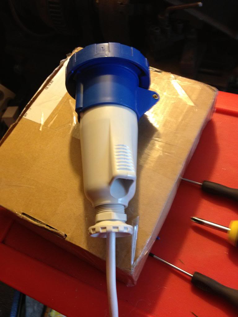
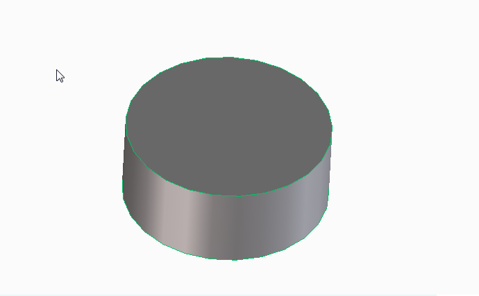
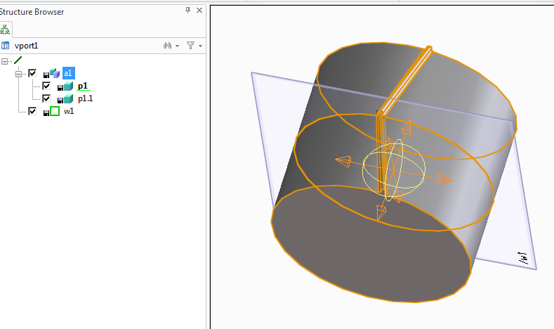
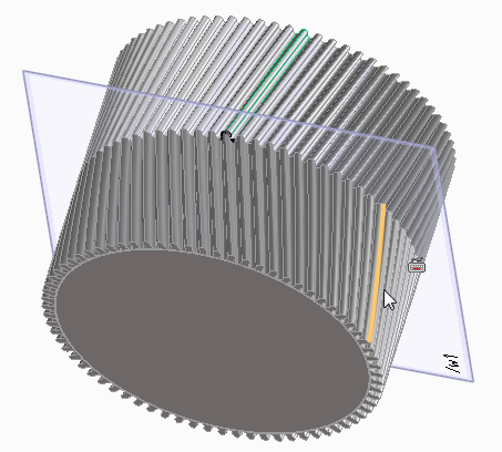
A few weeks ago I made a new heater for my solidoodle 3d printer, I was quite happy with the results, despite having broken a drill bit in my heater block, I got around that, and I decided that was my fault, I clearly wasn't drilling the hole straight, it was a small drill bit, and they often break anyway...

When I bought the aluminium bar to make the hot end I had decided that I would probably want to make something else anyway, so I got a 2 meter length.

After making that first hot end I decided that I was going to make and sell a whole load.
I had enough aluminium bar, I had bought a hundred heaters at the start of the project, (knowing that I could sell the heater elements on their own!)

So I started cutting up that long bar of aluminium into 100 small pieces.
by about the 3rd piece I gave up and went to ebay and bought a small hobby band saw. -this worked great for cutting the aluminium, right up until the blade broke -though this had come with the saw, (which only cost £30), and had made 99 cuts, -failing on the last)

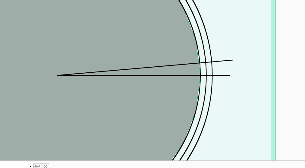
After this I got my set square and scribe and marked out where I needed to drill holes on all 100 blocks that I had cut. then I centre punched them. -this is time consuming, that was 600 holes that I marked!

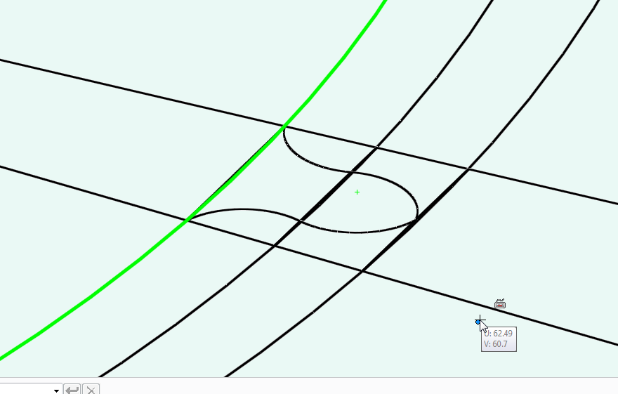
After this was done I decided that I'd start drilling, rather than drilling by hand I decided that I'd use my fathers pillar drill, a Draper tool, I dutifully loaded the drill bit into the chuck, and set about drilling holes, I started by drilling 2.5mm hole through all of the holes I'd marked, a lot of the holes needed to be 2.5mm, others would benefit from a pilot hole being drilled anyway.

However I found that on the point where the hole for holing the thermistor met the hole for the screw securing the thermistor, the drill bit would catch and break. this was the same problem I'd had with the hand drill, but now I was getting this with a machine drill, one that was square, level and had no lateral forces, clearly there was a problem with the way that the cut was being made, swarf from the hole was catching and causing the bits to break at an alarming rate.

Eventually I managed to get a few holes drilled carefully that did meet, (afterwards I bought some 2.5mm end mills that I would use in the drill to make these holes meet more successfully!

At the end of the time I had set aside that day I had 11 pieces half made, I had the holes for the thermistor set-up drilled successfully, and the long hole through the block pilot drilled. at this point I'd been at it around two hours, and decided that was enough... -and besides the drill had gotten quite warm and I thought it could use a rest!

One morning the following week I decided that I'd continue my project. however within ten minutes of starting the drill the motor had caught fire.

In the end I took the pieces home and finished the first batch with a hand drill.

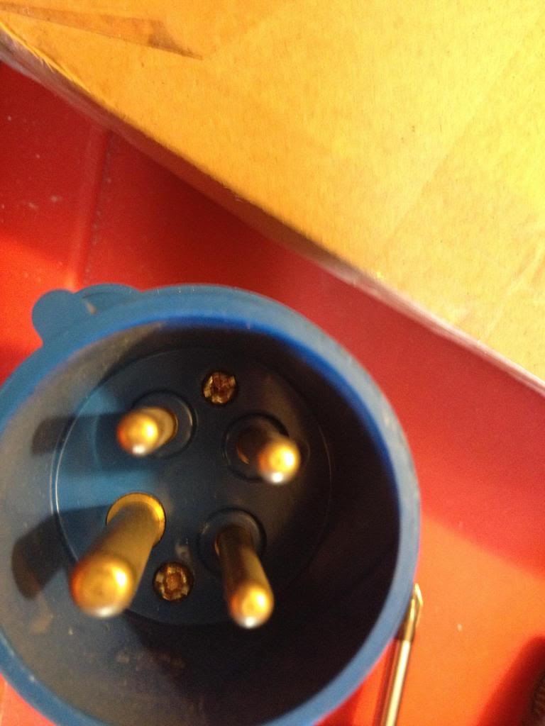
I tapped them and installed the heater elements.

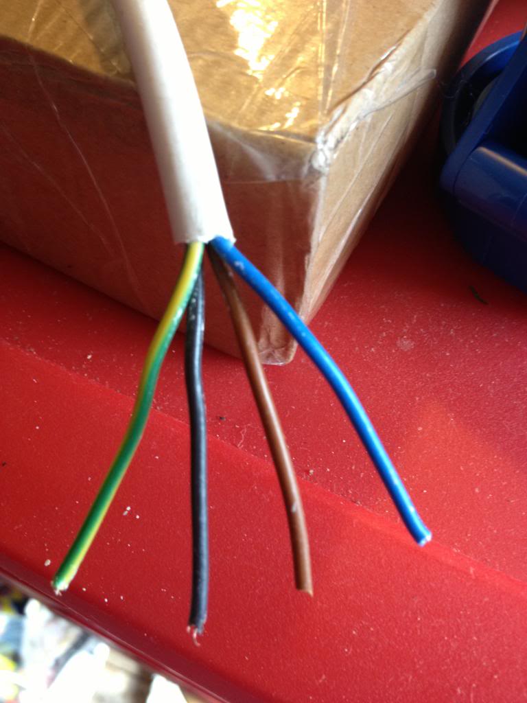
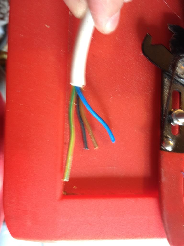
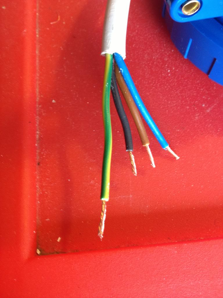
As it's a new month I've been paid and gotten some more money to spend on this project I've now ordered the thermistors, wire and heat shrink to finish these heaters up.


So... let's look at where I went wrong.
First, I'm hoping to sell these for around £12 - £14, this is in line with what others have sold for on Ebay.

the heaters were £130 + £15 import VAT for 100
Aluminium bar was £10
Thermistors are£70 for 100
heat shrink is £5 for the 6m of 1mm heat shrink I need
and £3 for the 5m of 3mm heat shrink I need.
wire is around £2 for 10 meters, (and I need 200meters) so £40
the grub screws cost around £15

So a quick sum up looks like I'm nearly £250 in the hole with materials.

Postage on each item is expected to be around £1. (so that's another £100)
Ebay will take ~£2 per item, (£200)
and pay pal will also want their 10% (£1.40 per item, times 100 = £140)

so that'll be around £700 of costs.
I'm hoping to sell these for a total of £1400

but here's where the problem starts....

now take roughly 25% of that away in taxation and national insurance that I'll need to declare. that's £175, leaving £525

Trying to do this cheaply has meant that I broke around £5 of drill bits whilst trying to make the blocks, and that £10 saw blade for the band saw.
(leaving £510)
I'd busted my dads pillar drill, because it's a hobby tool, not an industrial tool, it's meant to spend about 30 seconds being on, then have ten minutes to cool down, now spend nearly three hours in constant use, so that it over heats, and breaks down the insulation, (and then catches fire)
a complete replacement is around £300, second hand maybe £150, or a new motor will be around £100
My "profit" is now a pretty shabby £400...
then I spend a couple of hours cutting up the aluminium bar, a few more hours in front of the drill, a couple of hours sourcing materials, I'll conservatively spend probably 15 minutes per item with listing on ebay, talking to buyers, packaging and going to the post office to actually post the things.
(that's 1500 minutes, or about 30 more hours). I spend around an hour designing the thing in the first place.

Based on the initial ten I have that's 6 hours of machining and making,
So that 100 will be about 60 hours of machining, plus 30 hours of listing and posting.

So that £400 I've got remaining will need to pay for about 100 hours work. about 2/3rds minimum wage.

in other words.
I started out thinking, cool, the parts for this will make me loads of money, I'll spend about £2.50 on an item that I can sell for £14.

But,
using hobby tools has increased costs due to breakages.
Using hobby tools has meant that I can't work for more than an hour at a time without significant machine downtime to cool off, increasing the amount of time take to produce parts.
Funding this venture myself has meant that I've had to wait until pay day to get more funding. - I could have taken this to a kikstart project, but them I'd have 100 angry customers breathing down my neck saying that my lack of planning or prep wasn't their fault, and where is their money etc.


The long and the short of it is:
before you decide that you want to give up your day job and live the dream of running a tech startup. do your sums first. be realistic.
I was wishfully thinking that I might get around £700 for what would be an easy day stood at a band saw and a drill. -actually I was thinking I could use an ordinary hack saw to do this work!

What I though would be around £100 per hour I'll retired a millionaire next week, has actually resulted in being a drain on time and resources. Maybe with a few thousand pounds of investment for industrial tooling I'd do better -but I doubt that also!

Monday, April 15, 2013

Making a Lego Table

So this is a nice short post that details the Lego table that was made for my Daughters birthday.


It's a pretty simple idea, rather than having lego all over the floor, (not that this will stop that happening) a special lego table is created, where models can be created and worked on, perhaps over a number of days.

The basis for this table is a cupboard from Ikea that is a bit like those old school cupboards, there are some plastic trays that will be used to store the lego in.

On the top of the table base boards are glued to the top.

This table uses 32 x 32 piece boards, (three of them) and 16 x 32 stud boards, (4 of them) and a single 16 x 16 stud board

The total areas therefore is 48 studs wide (32 + 16) and 112 studs long (32 + 32 + 32 + 16)
there is an equal border, (about a 3 stud lego brick size) around the whole top

The boards were glue using solvent free evo stick (contact adhesive) glue. obviously a solvent based glue would melt the ABS plastic that is used to make Lego!

When the table is all put together it looks like this:


You can just about see the way that the boards are offset to try to minimise the lines.


Monday, April 08, 2013

Creo Elements - More gears (yes more) spur gears, helical gears and herringbone gears

So I've done a couple of blog posts now on making gears, first by creating just a section of the gear. then replicating it around an axis
And by creating a big gear with a single tooth. then replicating it around an axis


Now I'll look at a third and final way of creating a spur gear, and show how this is also the way you need to make a helical gear, (with diagonal teeth) and a herringbone gear, (with herringbone -like little arrows teeth)

Even though this tutorial will show now to create all the gear types it's worth looking at the others, mostly because I'm only introducing the tools used once. so the lessons do build on top of each other, also, it's good to know more than one way of getting a part made.


We'll imagine the same scenario as the last post, that we have two axles 50mm apart and want two gears to link them.

The gears mesh together, so again we'll have the raise teeth of the gear protruding the 26mm radius, and the reciprocating grove in the gear at 24mm.

This time draw a circle that's 24mm.
pull the circle into a cylinder 20mm tall.

(you can pull to any height, but with the maths used later I'm using 20mm)

Now create a new work plane on that cylinder, draw guide lines for your tooth profile to be created, again at an angle of 5 degrees.

Once again draw a tooth profile onto the edge of the cylinder, your tooth crown should be 26mm from the centre.
Delete your guidelines that you've drawn and you're left with a single tooth on a cylinder again.

now clearly you can once again pull that tooth to 20mm height and replicate with rotational symetry, (like we did in the last two posts) to make another spur gear.

But this time I'm going to make a helical gear.

Select the helix add tool

Select the axis as the centre of the cylinder part.

Now the pitch and turns are related.

Our part is 20mm high, therefore if we select 20 for the pitch and 1 for the turn, we'll get a single complete turn of the tooth profile all the way around the part.

But we want a tooth that progresses about 5 degrees around the part.

To progress 5 degrees around the part we need 5/360 turns (roughly 0.01)
and to keep the same pitch to turn ration (to make the tooth reach the top of the gear) we need the pitch to change to 20/0.01 = 2000

Now we need to mirror the part to create all the teeth.

since each tooth takes up 5 degrees we'll mirror 72 times, at an angle of 5 degrees.
Giving us a helical gear.

Now imagine that we want a steeper angle on those teeth.
go back to the part where there is just the outline of a single tooth ready to be added as a helix.

now imaging that we want the tooth to extend 20 degrees around the gear.
we need figure our the turns first.

360/20 =~0.04

then we need to figure out the pitch,
20 (gear height) / 0.04 (turns) = 500


Once again, use the rotational mirror tool to make 72 teeth with an angle of 5 degrees about an axis that is the centre of the gear.

HerringBone
Alternatively.
Before mirroring the tooth rotationally, to create a herringbone gear mirror the tooth along the face first.


now you'll have noticed that mirroring creates a lot of individual parts. We're going to apply the rotational symmetry to the herringbone gear that we are creating, so we want to group the parts into a single assembally so that we only need to perform the mirror opperation once.

fter creating the new assembaly (a1) drag the two parts (p1 and p1.1) into the assembly.


Now double click a1 you'll see the edge lines of the whole assembly are highlighted.

And apply the radial mirror tool to extend the gear teeth over the whole gear.

Monday, April 01, 2013

Creo-Elements Tutorial - More gear making

Proof as ever that there is more than one way to skin a cat!

So last week I looked at a way to create a gear on Creo Elements, the approach was to create a segment of gear, that made up a specific fraction of the total gear, then design the teeth profile for a single tooth and then mirror that around a circle to create a whole gear.

Of course you could start with a circle and draw out the gear as a 2d shape and then extrude it all as one part, or you could make a cylinder and then use the pull tool to extrude the teeth in the cylinder.

The method that I looked at last week is good for designing gears, and other parts that have circular symmetry.

But as ever, there is more than one way to skin a cat.

So now I'm going to cover a new way to create spur gears.

This time the scenario that the part will be designed for is as follows.
I have two axles that are 50mm apart.
I need to link these with two gears, the gears should be the same size such that there is no change in speed of torque in the transmission.

Now the first thing to consider is that if these were rollers they'd both be 50mm diameter, touch and transmit force by friction alone, but as these are spur gears they need to have teeth that mesh into each other.


So we start by drawing a circle that's 50mm in diameter. (25mm radius)
then we'll draw another circle inside that with a 24mm radius and finally a circle around the outside with a 26mm radius.


These circles will form and guidelines for the gear teeth, (which will extend out some 1mm over the 25mm radius and nest into pockets 1mm inside of that 25mm radius on it's mating gear.

Now we'll add some guide lines for the amount of space our gear teeth will take.
so drawn a line from the centre of the circle along the 0 degrees line, then another on the 5 degrees line.

Now zoom in on where you will be making that tooth.

draw appropriate guide lines so that you'll have some points that will snap.
(join the points where you lines on 0 and 5 degrees cross the circle, then halve those lines again. this will form five points 0, 25% 50% 75% 100%, at each circle guideline.

Now use either the line tool, or the radius tool to create a tooth profile.


Now delete all your guidelines inside the outer circle, (leave the circle so that you can find the centre for the arc you'll create next.


Now using the three point arc tool, draw an arc from the base point of the gear tooth, in a wide arc.

Now delete your remaining construction lines so you have a 1 tooth gear.

Pull this single tooth gear to a cylinder.

Now use the rotational mirror tool to create a rotational symmetry to fill on the remaining teeth.

Now you have another gear.


Monday, March 25, 2013

Creo-Elements tutorial -Making gears

So I thought it might be time for another kind of lets teach something blog post.

So,

Making gears with Creo Elements

So I'm going to design an actual part (that I will be using in the creation of my own variant of 3d printer, (I have an idea in my head for this at the moment).

The pulley that I'm going to print now will need to accept T2.5 belt, (5mm thick) and will need to fit over a standard skate bearing (608Z)

So lets have a look at what that actually means.
First we'll have a look at the skate bearing.

These have an outer diameter of 22mm

This means that my pulley wheel must have a hole in it that is 11mm radius.

Next we look at the specification of t2.5 belt.


Basically, any point in the belt to the same point on it's adjacent tooth is 2.5mm.
Each peak is 1mm, each trough is 1mm, there is a slope to the teeth that accounts for the remaining 0.5mm, (a 0.25mm slope)

However, on the pulley I won't put the slope in, I'll leave a sharp angle to allow the belt to bend.

To we're looking at a 1mm crown, and a 1.5mm grove on the t2.5 pulley.
Now we need to figure out the outside diameter of the pulley.

Start by deciding at least how big it must be.

The hole in the middle is 11mm.
We want at least 1mm over the width of this bearing. so we say that the pulley must have a radius of at least a few mm more than this.

Now lets work out the circumference.

14*2 = 32 * pi =88.116
so the outside circumference would be 88.116mm.

I'll round that up to 90mm circumference.
that give me

90/2.5 teeth = 36
each tooth has an angle of 360/36 = 10 degrees

If my circumference is 90, then my radius must be
90/pi / 2 = 14.29mm

I'm going to create a 14.3mm Radius T2.5 pulley wheel, with an 11mm hole in the centre.


So start by drawing a single line that's 14.3mm long on zero degrees.
then a second line 14.3mm long on ten degrees.


Now draw a line 1mm coming into the part, toward the other line.

Then a line that goes towards the centre of the part at a perpendicular angle, that's 0.7mm long (the height of a T2.5 tooth.

finally draw a line directly to the opposite line.


This won't be exactly 1.5mm in length as it's shortened by being closer to the centre of the pulley

now delete the line on zero and redraw to the correct size.


Now you have one thirty sixth of your pulley wheel.

Use the pull tool to make the gear segment 5.5mm tall, (the intended belt width is 5mm, so this adds some space for fit.


You now have a slice of gear.


Next you need to select the structure tab,
pull down the copy part options and select radial copy.

You'll need to copy, 36 times, (there are 36 teeth)
with the axis set at the centre of the pulley
and the angle of each segment is 10 degrees

Press ok and a new gear is produced.

Now delete the work plane.
Now select the circle tool and click on the gear to create a new work plane,

Drag the circle from the centre of the gear to a 15mm radius.

Use the pull tool to make the top of the gear 0.75mm high

repeat on the other side.

Now use the chamfer tool set to 0.5mm to add a slight grove to the pulley wheel edges, this will held reseat the belt if the alignment is slightly out.

now use the circle tool to create a circle with an 11mm radius, and use the pull tool to pull to a depth of -7mm to remove the centre of the pulley wheel.

Now we have a pulley wheel.
It fits over a standard skate bearing.
It has 36 teeth at a T2.5 pitch.

(this will be an idler pulley in the drive system)


This can of course be used to create spur gears as well as pulley wheels, sprockets for use with chain drives, all you need to do is work out the appropriate angle and make your tooth profile fit the job then replicate it.

You can also use this method for making other repeating shapes, for example, spoked wheels, clutch plates, fan assemblies. etc