Showing posts with label amplifier. Show all posts

Monday, July 02, 2012

Fixing an Amplifier 3

Fixing an Amplifier: 3

So that Fender Blues junior amplifier has come back under my nose, and it has a very weird problem.

Altering the volume knob makes it sound like it's tuning a long wave radio.

it whistles and hums, you can modulate the whistling sound bu altering the volume and tone.
something is definitely not right.


Trouble shooting.
So the first thing to do it try to figure out what's wrong.
Clearly there is something unstable and oscillating inside the amplifier, and this is causing random and weird noises to be picked up and generated.


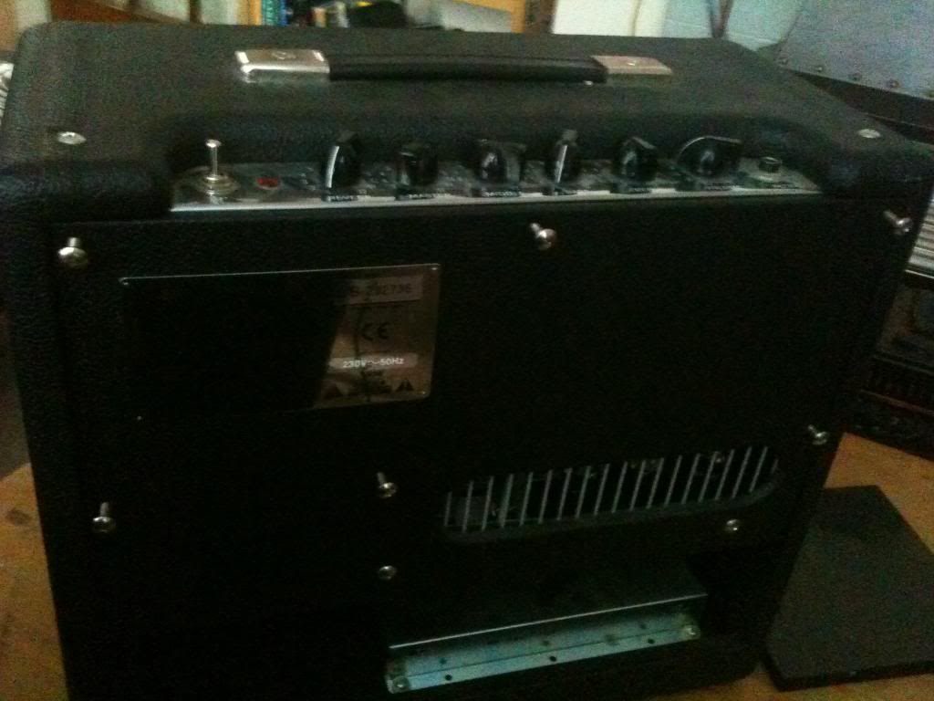
So first, I take the back off.
have a cursory glance for anything loose or disconnected.
I can't find anything.

I plug the amplifier in and see if anything looks a little out of place, or weird.
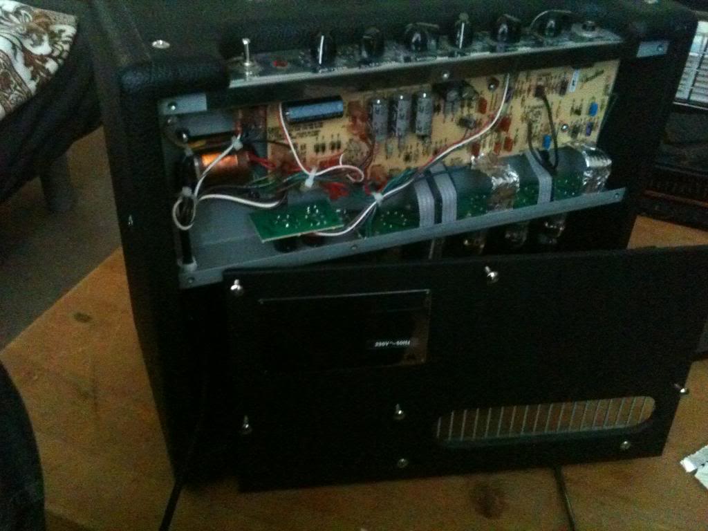
the humming starts again, (notice the humming is worse because the main board is no longer completely shielded.)

Lightly touching the ribbon cables that connect the main board to the valve board produces interference, it seems that the low voltage signal going into these boards is particularly susceptible to interference.

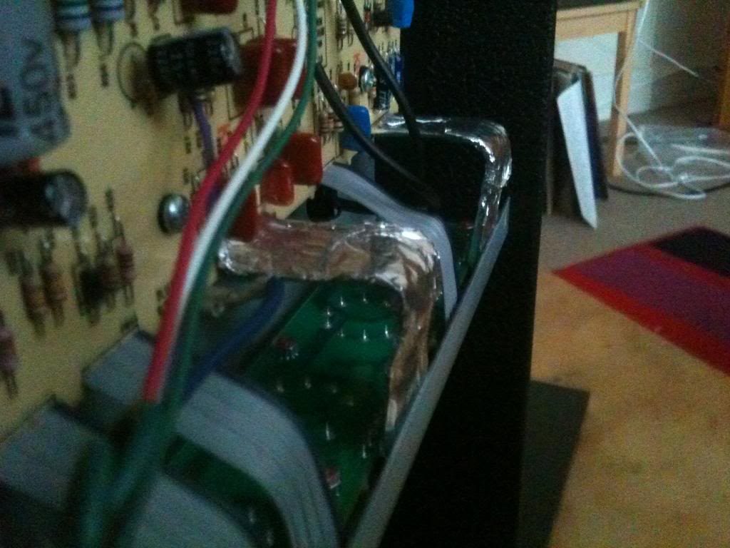
In order to reduce this problem the ribbon that carries the instrument signal to the pre-amp valve, and the ribon cable to the valve used after the reverb recovery amplifier are shielded in aluminium foil.


The amplifier now has slightly less interference, but when adjusting the volume the weird noise (though not as pronounced) is still there.


Now I begin inspecting the circuit diagram in detail.
It seems that there is not really a lot to go wrong in these amplifiers, in fact the only thing that can go wrong is, Valves break, reverb recovery amp any break (but very unlikely without excessive abuse) and electrolytic capacitors leak.

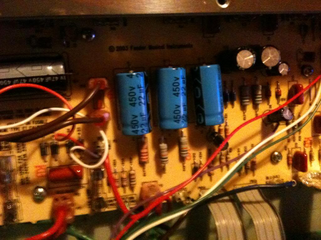
I looked long and hard at every electrolytic capacity on the board, and found that one of the four large grey filtering capacitors was slightly deformed.

Searching on-line led me to find that what appears to have happened is, in some inane bid to save money, Fender bought the cheapest sub par quality components that they could find. there are loads of stories of these leaking, and bulging and stopping amplifiers working.

So I ordered some more capacitors and changed these for new (and better quality) ones.


the amplifier is now working perfectly again.

I have left the foil shielding on the ribbon cables, this adds a slight capacitance to the circuit and rolls off the brightness of the amplifier slightly.


Monday, June 11, 2012

Electronics lessons: Music effects: The distortion pedal

This is the first guitar pedal that I eve made...

What is distortion.
Distortion is the changing of a wave form from one form to another so as to distort it.

Technically speaking, a tone control distorts the signal, a envelop filter distorts the signal, anything that "colours" the signal also distorts it.

but if I stop being a smart ass for a second.

distortion to most people means fuzz.

History of overdrive.
It seems to make sense to me to start at the very beginning, and lets take a look at the physics of what's happening.

Many people try to make a distinction of what type of distortion they are listening to, if it's a hard clipping, or soft clipping, some people thing that an over drive and a distortion are different, they kind of are, but fundamentally it's all the same.

OK, distortion was around long before this, but lets set the scene...
To understand this analogy you;re going to need to know what a green back is.
A green back is a speaker made by the British speaker manufacturing company Celestion in the 60's or 70's.
It was a basic run of the mill speaker, which has gained cult status (and price) with it's inability to handle the power of the signals that people were trying to drive thought it.

Now you might think that from the description above of a basic speaker that's gained notoriety for sounding bad might make you think that I dislike it.
nothing could be further from the truth. the point I'm getting at here is that the magic sound of 60/70 British rock, (think Rolling stones/Yard birds/Led Zepplin) lays a lot in the mechanical and electrical limitations of the time.

Consider how a speaker works,
a coil of wire is suspended in a permanent magnet,
the coil of wire is subject to an electrical current, this makes the coil magnetic, where it will be either attracted to, or repelled from the permanent basket on the back of the cone.
the coil has a paper cone attached to it.
as the coil moves the paper cone moves, this moves air particles, which vibrate through the air and then the air vibrates against our ear drums and happy days we hear sound.

So we get that the coil is moving, and we get that we can turn the volume up and make it move more, but, the coil is attached (with what's called suspension) to the metal frame (spider) in the speaker construction. The size and stiffness of the suspension limits how far that speaker cone can move.
that means that for very large wave forms the speaker will not replicate exactly what is being asked of it.
it tries to reach the point where the signal applied it telling it to go, but excersion limits are met and the speaker cannot move any more.
additionally the suspension on the speaker slows down the cone as it reaches the excursion limit

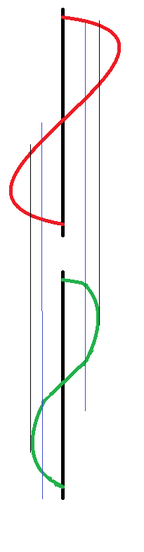
So the following picture hopes to show you what I mean, I've drawn it on it's side so you can visualise a speaker cone going in and out.

The thick black line is zero, this is where the speaker normally rests.
the red line is the input to the speaker.
you see it rising, the green line (speaker position) moves with it, then we reach the blue line, this is nearing the excursion limits for the speaker, so whilst the red line continues to move, the green line is being slowed by the suspension of the speaker.

The red line continues to rise where it meets the black line, this is the excursion limit the speaker can no longer move at all past this point whilst the red line continues to be at this point the speaker sits as it's maximum excursion position waiting for the red line to fall.

This is, in the most traditional sense an over drive distortion.
the wave is quite smooth, (as the suspension prevents square edges to the sound wave) and as such will sound like a warm fuzz.

It is also possible to get over drive distortion from an amplifier.
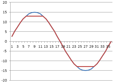
Consider the following chart.
the blue wave is what we want. the red wave is what we get

lets say we have an amplifier with supply rails of +15 and -15 volts, you we give the amplifier a 1v / -1v signal and say, amplify that, and set the gain to 15.

What should come out of the amplifier is a smooth wave (the same as went in) with peak values of + and - 15 volts.
but we can't actually drive the amplifier to the supply rail voltages, the most that we could get out is +13 and -13 volts, so the top and the bottom of the votlage is cut off.

This is a much harder clipping sound.

Now that we've listened to loads of music and realised that the classic hot sound of the 60/70s is so desirable what can we do to emulate that?
(clearly we don't want to run our amplifier at that level forever, and the amount of power that you need to put into a speaker cone to reach cone excursion limits makes your show loud, (and perhaps not suited to the venue size you have!)

So you want to fake it.


Well, now that we know what we're trying to fake, it's a very simple matter of finding a way to cut a little from the top and a little from the bottom of an audio wave.


So what we want to do is take a small wave form say 1 or 2 volts then shave a small amount of voltage off of it.

So what we want is a component that can give a low resistivity for small signals, and gradually that resistivity will increase until it hits a limit then it will only allow that amount of signal to pass.
kind of like some kind of flow control.


well, we don't exactly want flow control, but if we look at the diode we have the component that we need.

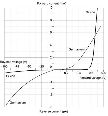
the following graph shows the voltage and current flow of a regular silicone an germanium diodes as they approach their forward conduction zones:

You see that (especially with the silicone diode) there is a gently slope on the voltage vs current graph, this is that component gradually decreasing it's resistance to a signal, until it reaches ~0.65 volts where it begins to conduct, at 0.7 volts the junction inside the diode is saturated and it's in full conduction mode.


So what does this mean for our distortion effect.

Well, quite simply, we wanted a component that we could use to clamp our voltage inside an artificial set of parameters that would mimic the gentle slowing due to suspension and then flat constraint of an over driven speaker. and with a diode we actually have that.


There are two ways of using diodes in a distortion circuit, these are often called hard and soft distortions.
what makes a distortion hard is very angular edges on the wave form when it flattens off, (see the picture of the amplifier distortion above, and soft distortion is more controlled, the distortion still exists, but it's smoother.

not only does the wave look smoother, but it sounds smoother too!.

There are two ways to use diodes to produce this distortion.

First we need to understand the building block that we're using.

two diodes are placed back to back, (and front to front)
this looks like a crazy way to put a diode,-surely they'll just conduct to ground regardless of the signal applied and there will be no output?

Well, no they won't just conduct to ground because as explained above, as the diode is switching on it has a resistance, and even when it's on there is a voltage drop.

So what actually happens is we clamp the signal line to only permit signals within a certain threshold, and limit any larger signals to that threshold.

So now we have a simple model.

for signals under 0.5 volts a diode acts much like an open circuit,
for (silicone) 0.5 - 0.7 volts a diode acts like a resistor with progressively less resistance being applied as the signal rises
for germanium diodes 0.2-0.3 volts acts like a resistor with progressively less resistance being applied as the signal rises
for signal over 0.7 volts the diode acts like a short circuit grounding the circuits and therefore clamping the signal to the activation energy threshold.


now that we have this component block figured out we can look at how to apply to to a circuit.

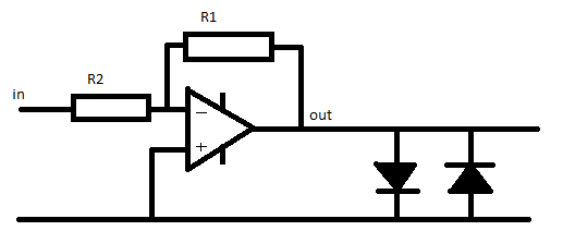
The first method of connection is to follow the amplifier that is used in the circuit with the component block.

This literally clamps the output to 0.7v, this type of circuit arrangement is suited to either Light emitting diodes or germanium diodes.
the use of silicone diodes produces a quiet hard clipping in this position, mixing a silicone diode and a germanium diode in series for the block can have a positive effect in making this clipping less harsh.


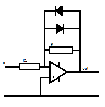
The second way to use this component block is in the feed back network of the inverting amplifier.

we put the network in parallel with the feedback resistor.

At low signals the diodes act like an infinitely large resistor.

so the value of 1/Rfn = 1/Rf + 1/diodeR(infinity) therefore the total value for the resistor network (Rfn) equals Rf

so if R1 = 100 Ohm, and Rf = 200 Ohms,
Gain = -Rf / R1 so the gain = 2

now as the signal gets larger the amplifier will put out a larger signal, when the output of the amplifier reached 0.55v the diodes are behaving like a resistor.
we'll (for the sake of simplicity) say that the value of this acting resistor is 200 Ohms.

now the feedback network has a resistivity if found by the equation
1/Rfn =  (1/200) + (1/200)
so Rfn = 100 Ohms

now the gain of the amplifier is
Gain =-rf/R1
gain = -100 / 100 = -1

so the gain has gone down.

Now the voltage continues to rise to above 0.7 volts, the diodes now act like short circuits.

the resistance of the feed back network a 1/Rfn = 1/200 + 1/0  so Rfn 0

and the gain is
-0/100 which also equals zero.

Remember a gain of 1 is unity.
the output = input x gain.

so a gain of zero actually turns the output off completely.
(but if that were to actually happen the there would be no voltage so the diodes would have infinite resistance again.

thus the voltage is again clamped in the region of the diode conduction threshold.


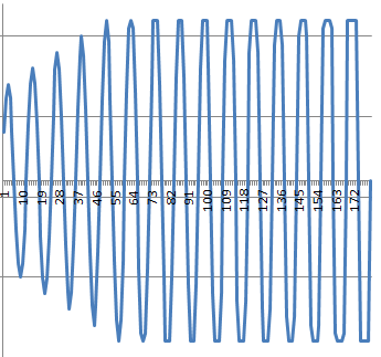
You can see in the graph below what a gradually increasing waveform looks like as it approaches the clipping region.
at the start there is no distortion, as teh wave gets gradually larger the clamping effect of the distortion begins to take effect, you see by the end of the graph the distortion is no longer smooth, the input signal is massive and the clipping is more and more choppy (and will sound worse)


Monday, May 14, 2012

Simple Circuits: signal mixers

A couple of weeks ago I introduced a new component in an "electronics lessons" post, that component was the op-amp, since then I introduced the idea of using it as a level meter.

I've kind of stayed away from saying here's an amplifier, because, simply, I already gave the circuits, inverting/non-inverting, there you go, pick resistors to set the gain and build voila a simple amplifier.

What I'm going to look at in this lesson is an amplifier that's a little more complicated.


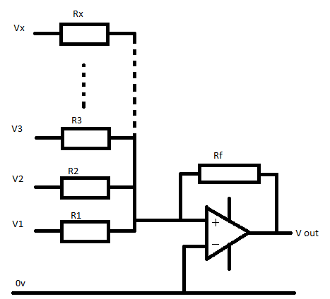
Summing amplifiers

Summing amplifiers are essentially amplifiers that take a signal and produce it's sum.
they are inverting amplifiers so bear in mind that the sum is negative, and would need to be flipped by a final amplifier.

If you take an example amplifier with two inputs:
The voltage on input 1 = 1, and the input on input 2 = 5, we'd expect the output of the amplifier (assuming gain=1) to be -6, 1+5 = -6 (minus 6 because it's inverted)

Resistor networks
As you may have guessed the output voltage of the summing amplifier is dependant on a network of resistors, and (yay) more maths...

the voltage at the out put is

Vout = -Rf ((v1/v1) + (v2/r2) (and so on))

so in the above example of a summing amplifier with two inputs.
if we make all the resistors 10Ohms we have

v out = -10 x ((1/10) + (5/10))

vOut = -10 x (0.1 + 0.5)
vOut = -10 x 0.6 = -6 (just like in the above example)

if we have three resistors the equations will be

vout = -Rfeedback x ((v1/r1) + (v2/r2) + (v3/r3))

The summing amplifier is infinity expandable, and is a critical component of a mixing desk.
an 8 channel mixing desk is simply an 8 channel summing amplifier.

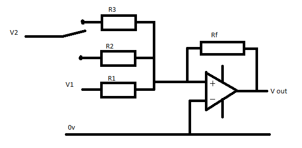
Loud switch

Lets assume that we have a two channel amplifier.
the voltages at input 1 are both 1volt signals.

R1 = 10Ohms
R2 = 10Ohms
R3 = 5Ohms
RF = 10 Ohms

There is a switch that will select wither the 5 or 10 Ohm resistor for V2

the output looks like this

Vout = -10 (1/10 + 1/10) = -2

and when the "loud" switch is pressed on channel 2 it looks like this

Vout = -10 ( 1/10 + 1/5) = -3

that 3 volt output is made of 1 x v1 and 2 x v2 so we see the signal on channel 2 (that is V2) now appears twice as loud as the source attached to V1

Monday, April 16, 2012

Electronics lessons: Operational amplifiers

The last electronics lessons covered long tailed pairs, I talked about the best operation being gained when they were subject to the exact same environmental conditions, and to do this the transistors could be built on the same substrate of silicon.

Well enter Operational amplifiers, Op amps, comparators, op amp comparators.

they little guys seems to have many names, but they are the same thing, often the same part.
The reason that they have different names is the way in which they are used.

when investigating the long tailed pair we established that the output was (v1 - v2) x gain

The same is true for the operational amplifier.

Most operational amplifiers are extraordinarily high gain amplifiers, however we can use feedback to reign in that large gain.


So, to start with, let's look at the use for infinite gain differential amplifiers.

we talked about the long tailed pair and how the difference between v1 and v2 was amplifiers.

for example,
if v1 = 5 and v2 = 3, and the gain = 4
(5 - 3) * 4 = 8
The output would be 8.

the same is true of comparator amplifiers. except the gain is very very large
(5 - 3) * 1,000,000 = 2,000,000
except the output is not two million volts, because the supply to the circuit is only 12 volts, so the output will be 10 volts.

Yes, ten volts, the maximum output is supply rail voltage - 2 in most chips, (for example the LM741 chip)

This means that we can use the op-amp as a switch, comparing the voltage applied to v1 and v2, (positive and negative,/non-inverting and inverting, or pin 2 and pin3 in the case of the LM741)
where the switch will come on if the signal voltage applied to the non-inverting input goes above the reference voltage applied to the inverting input.

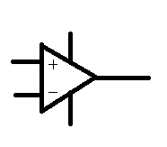
The circuit symbol is a triangle, this is (in black box block diagrams) the symbol for an amplifier, given that the op-amp is a hugely complex circuit packaged nicely in a black box, it seems fitting to use this symbol.


The pin outs are as follows, there are two inputs non-inverting (+) and inverting (-), the the output comes out of the point of the triangle, the two lines going into the top and the bottom are power lines, if there is only one power rail (no split rails) in the circuit then these may be omitted from a circuit design.

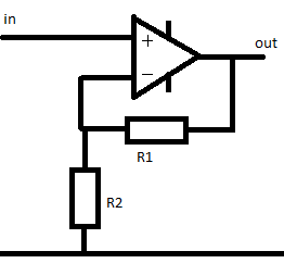
Non-inverting amplifier


We can reduce the gain of the amplifier using a network of resistors. when we made the common collector amplifier we made an inverting amplifier, that was when the signal to the base of the transistor was high, the transistor was in a state of conduction and the signal at the collector was low, (the same as the emitter)
When the signal at the base for the transistor fell the signal at the collector rose as the transistor stopped conducting allowing the supply voltage to exist at the output path.
that was an inverting amplifier.
input signal rise and output signal falling is inverted.

the non-inverting amplifier works in a way where when the input signal is rising the output signal is also rising.

the gain of this amplifier is
Av = 1 + R1/R2

if R1 = R2 then the gain is 2

1 + (50/50) = 2

if R1 = 10k and R2 = 5k

1 + 10k / 5k = 3

so for each 1 volt seen at the input, three volts will be seen at the output


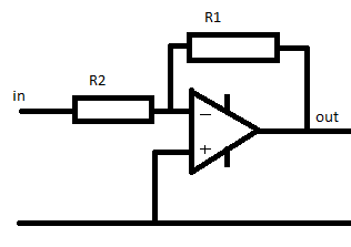
Inverting amplifier

The inverting amplifier is a little different.
(notice that the amplifier has been flipped upside down, and that the negative connection is at the top now.

the gain of this amplifier is
-R1/R2

So in this case if R1 = 10k and R2 = 5k the gain is
-10k/5k = -2

that doesn't mean that the signal is twice as small, it means that it's twice as big, but inverted.

for each 2volts seen at the input there will be 2 x -2 = -4 volts seen at the output

to reduce the signal you'd make R2 smaller than R1
e.g.
-5k / 10k  = -0.5
now for each 1 volt seen at the input there is -0.5 volts seen at the input.


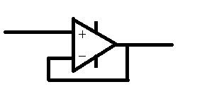
Unity gain amplifier

The unity gain amplifier does exactly what it says on the tin the output is at unity with the input, there is no gain.

So you might wonder what's the point.

Well. consider loading.

We know that power is equal to voltage times current, and that voltage is equal to current multiplied by resistance.

Realistically a microphone can supply fractions of volts, with fractions of watts of power.

We're talking in the realms of 0.1 volts (100 millivolts) and a power capability of something like 0.000001Watts


but to make the maths nice and easy, lets say that we have a 10 volt signal, that's capable of supplying 10 Watts

the maximum current available is 1 amp, (w/p = 10/10 = 1)

but what if we're trying to put this into a load of say 5 Ohms,

10 volts and 5 ohms, = 10/5 = 2amps drawn, but we aren't able to supply 2 amps, so the signal is going to be reduced, (the voltages will sag)
we're more likely to see around 7 volts, through that 5 ohm load which will draw out 1.4 amps ,(and 1.4 * 7 = 9.8watts roughly equal to our maximum power.

well a unity gain amplifier has an incredibly high input impedance.
now our 10 volt signal is looking at a 1million ohm load
10/1000000 = 0.00001amps, a tiny amount of power, which means that the signal is not loaded and does not sag.

in addition to this the unity gain amplifier as an incredibly low output impedance, meaning that you can drive very low ohm loads without the voltage getting loaded and sagging.

Monday, January 23, 2012

Fixing an amplifier 2

Though the article is called fixing an amplifier 2, that's because this is the second time that I've been asked to fix an amplifier by a friend, note it's a different amplifier, the first amplifier fix was good and it's still working.

So, what's actually wrong with this amplifier.

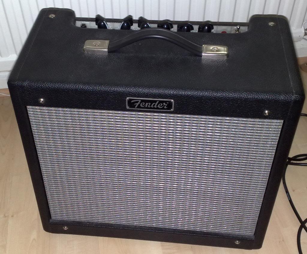
Well, the amplifier is a fender blues junior. these are some (in my opinion) very neat little amps, they have a kind of classic warm blues sound to them, they sound great when they are played at a medium level with a lovely clear signal thought them. They don't do that rocking blues, but they do clean blues sounds really well.

It's come into my hands because the reverb circuit appears to have stopped working.

One of the very cool things about this amplifier from a yes you can fix it point of view is that the circuit diagram actually comes with the amplifier, a quick look at the circuit shows that it's a fairly straight forward reverb circuit.

The signal splits after the pre-amp, and there is a clean channel and a reverb channel, the reverb channel goes to the reverb tank, then after the reverb tank comes back to a recovery amp, then into a mixer circuit where the time delayed signal is mixed to the clean signal to create reverb.

So the first place to look logically is the first component in the circuit.

The reverb tank.
in a guitar amplifier is is most usual to find spring reverb units. the unit works like this.

at the start of the reverb there is an electromagnet, the audio signal goes through the coil of the electromagnet.

that creates a magnetic field that varies in strength according to the music.

the electromagnet acts to move a spring.
the movement at one end of the spring travels through the spring to the other end, where the the springs are contained in wraps of wire.
the spring induces a current in these wraps of wire, (moving magnetic material in a fixed coil induces electricity).

that very small induced electronic signal is then amplifier and mixed back into the original circuit.

the springs work because they are metal and thus conduct the magnetism applied to them as well as the vibration incurred as the coil is energised with the musical signal, in a straight wire this may introduce delay, but the springs, (being as they are springy) bounce around, even after the original signal is recovered the springs will still be bouncing, eventually (as the springs are under tension) the transmission springs movements dampen down until they stop.

It's this dampening that causes the multiple echo sounds that we call reverb.

Back to the amp
In order to test the reverb tank you will need a multimeter.

First unplug the round connector that is at the input side of the tank, and measure the resistivity of the reverb tank, (connect one probe to the centre of the connection, the other probe to the outside.

Make a note of the resistance.

Next unplug the connector on the output side of the reverb tank and measure this.

These reading should be reasonably low. I can't remember off the top of my head what they should be, but one side was reading quite low, not so low that it seemed like it might be shorting out.
The output side was reading very very high, so high that it was likely that there was a break in the coil.

I ordered a reverb tank on-line and replaced the tank. and this amplifier started working again.

30 minutes, and taking out four screws was all it took to fix this amplifier.

Monday, October 17, 2011

Fixing an amplifier 1

The problem with this amplifier is that the input jack is a little hit and miss.

When you plug the input in, there is a 50:50 chance if the amp will make a noise, wiggling or holding the jack seems to make the circuit complete, so it seems that the amplifier is working, but the jack is not.

However, along the way, I managed to break this amplifier more than it already was, and had to replace part that were non-standard with standard parts that I had to customise.


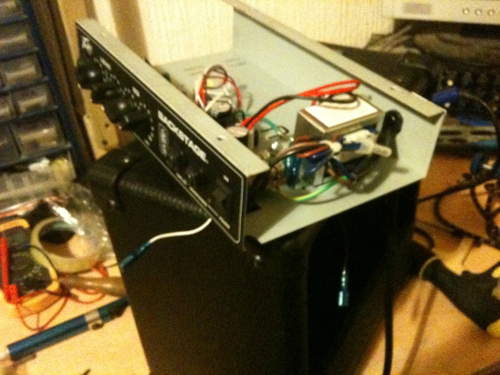
The amplifier in question is a Peavey Backstage amp, a tiny little guitar practice amp thing.
The basic problem is that sometimes you plug the guitar in and it works, sometimes you plug the guitar is and it doesn't work.
sometimes you plug the guitar in and it works, but only if you wiggle the jack lead around in the socket.

Basically, the input jack has for one reason or another seen better days, and could do with repairing.

Start by disconnecting the speaker wires, to ensure that you re-attach them with the correct polarity, (and thus correct phase) write down which terminal the white wire comes from and which wire the blue one comes from.
Next, remove the four screws on the top of the amplifier, and sliding out the tray that holds the electronics, push from the front, to the back.

next remove the wiring for the transformer, and output power transistors as these are mounted on the chassis case, and remove the circuit board from the case.

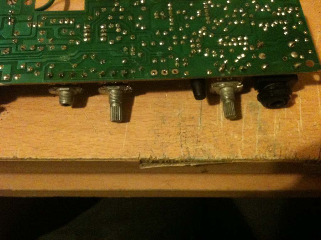
In order to remove the circuit board from the case, you'll have to remove the plastic knobs from the front panel, these just pull off, or at least should just pull off.

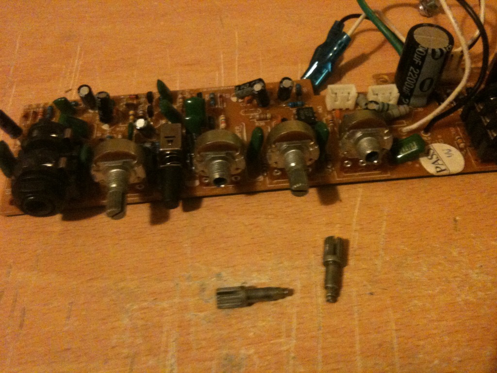
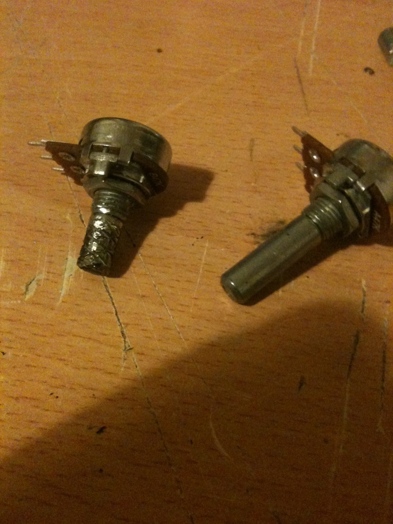
This is where the first "challenge" of the build started, when removing the knobs the potentiometer came apart on two of the controls!

This is no trouble, all I needed to do was replace the potentiometers. I could see that they were the small type, (mini pot) as the body was about the size of a 1penny piece, (instead of the regular size of just smaller than a 2penny piece).
looking at the body of the pot I was able to determine that I needed a B47K (linear 47k pot) and an A10K (I think) (Analogue 10k pot)
So I nipped to the shops and bought 2 mini pots of the correct size.

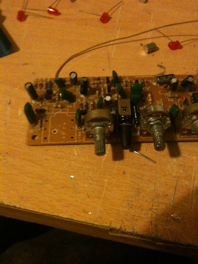
the only trouble is, rather than receive pots with a stubby shaft with straight splines attached, I received a pot with a long smooth shaft. Alas, I found that I could buy small splined pots, if I were willing to wait a few weeks and pay twice as much, or I could use the pots that I could get and make them fit.


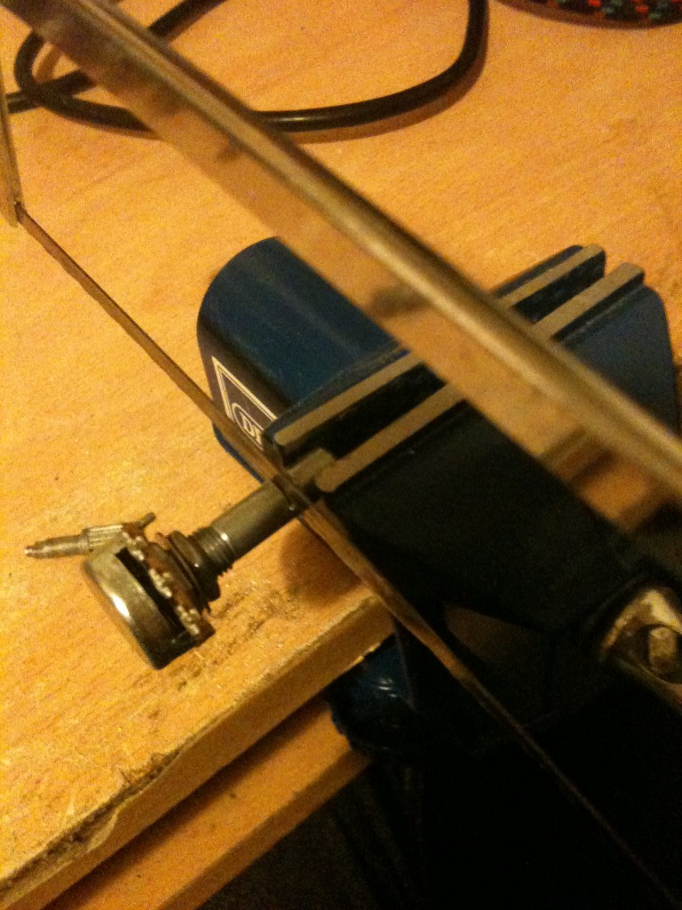
to make them fit, I need to shorten the shaft, and then put a texture into the shaft such that the plastic knob will have something to grip.

so, step 1,
Put the pot next to one of the existing ones on the board, use a marker to mark the length that the shaft needs to be.

step 2, cut the shaft.

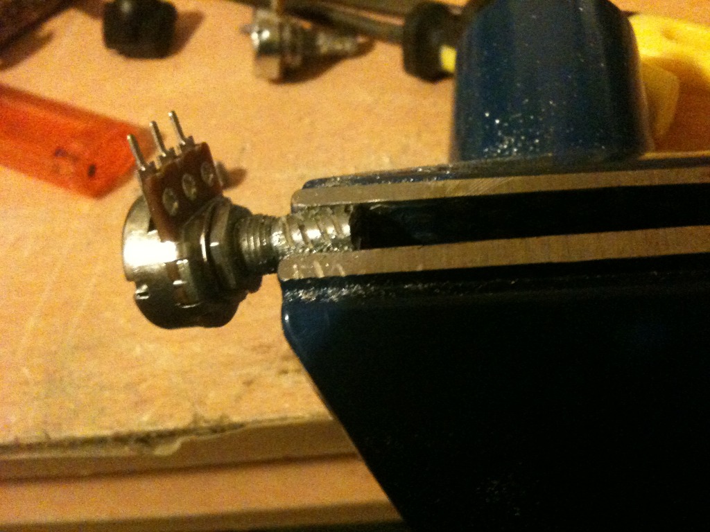
step 3, hold the newly shortened shaft in a vice, and using a needle file score a spiral pattern into the shaft.

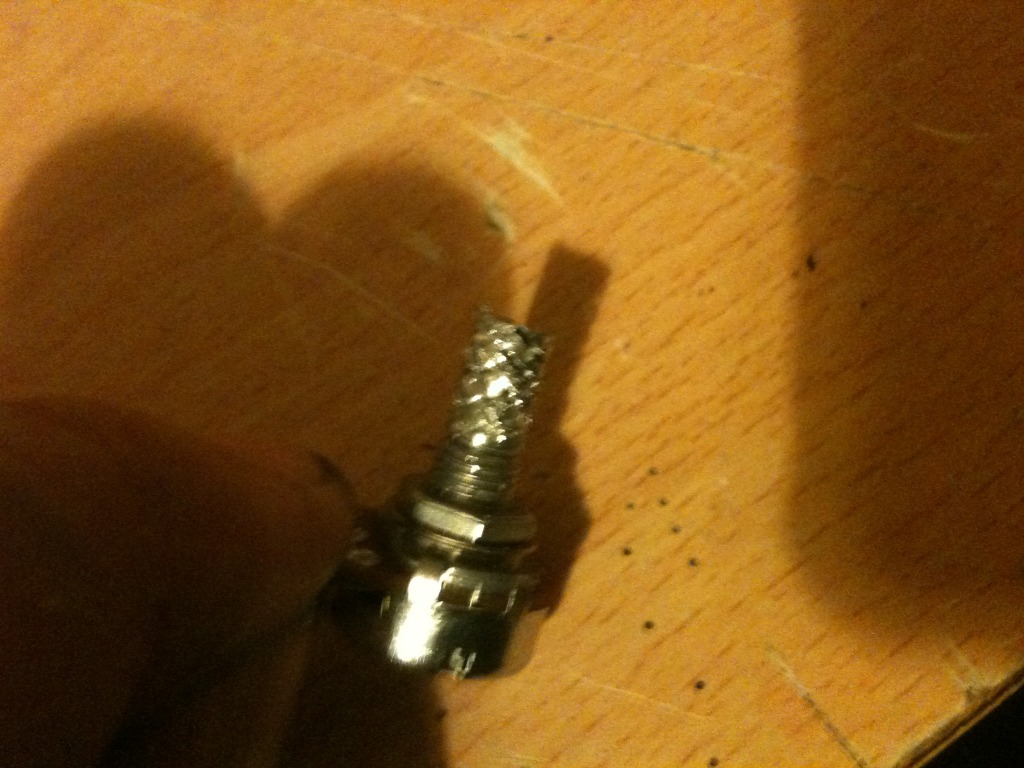
step 4, reverse the spiral pattern to give a knurled looking finish.

Here's a picture showing an unaltered pot next to my newly customised one.

Now remove the old broken pots from the amplifiers circuit board, (Don't do this at the start, else you may forget which is meant to be the analogue one and which is the linear one!)

now solder in your new pots.

Now it's time to replace that jack socket.
simply remove the jack socket by de-soldering it's 4 legs,  pull out the part and solder a new one in!

screw the circuit board, back to the chassis.
plug in the transistors and transformer again.

slide the amplifier tray into the back of the amplifier.
insert the four screws into the top that hold the tray to the amplifier body.
re-attach the speaker.
now test the amplifier.

Sunday, October 09, 2011

Electronics Lessons: The Amplifier

OK, we looked at a transistor amplifier, and will go on to look at operational amplifier circuits.

One thing that I didn't do was measure how "good" these amplifiers were. I think that everyone has had a bad experience with an amplifier at one time of another, something that just sounded weird, and not quite right. but perhaps you didn't even notice until you heard something better, then went back and listened to the same amplifier again.

So lets look at amplifiers on some more detail, explaining some of the words used.
-this is just a quick guide to some terms that you will find in amplifiers, their use and design.

Distortion (clipping)
The easiest way to explain clipping distortion is to look at what causes it.

Imagine that you have an amplifier that have a positive supply voltage of +5V, and a negative supply voltage of -5V.
The amplifier has an input signal applied to it of +/- 1V peak to peak and a gain of 2.

The input is a lovely sine wave, rising an falling between 1 and -1 volts,
The output wave is a similarly lovely since wave between 2 and -2 volts.

Now if you increase the gain to six.
you would expect the output wave to now rise and fall between +6 and -6 volts in the same perfect sine wave, except, it can't the supply voltage to the amplifier circuit is only 5v so instead the wave goes up to 5v, then there is a plateau where the top of the sine wave should be, before it levels out and falls to -5v and plateaus again where is should be falling below this.

You are effectively over driving the amplifier, trying to force it to amplify beyond it's means. the top and bottom of the signal gets clipped off.

Headroom
headroom is a weird one, it's not something that you're ever going to see on a data sheet, because it's just a made up figure, it's something that you either have, or don't have, but I include it because I feel that it's important.

Headroom is a measure of how much power you have left in the amplifier. For example: say you need at least 100W of sound to fill a particular room with sound, that would suggest that you need to buy a 100W amplifier right?

Well sort of yes, and sort of no, if you need the full 100W of the amplifier, then you'll be turning the amplifier up full driving it to it's limits (and possibly beyond and possibly clipping the signal) then you've not specified a big enough amplifier. Sure you fill the room with sound, but what about the quality of that sound?

If you need a 100W amplifier to fill a room with sound, you're better suited to buying a 200W amplifier, in that way you only need to turn it up half way to get your 100W of power, the amplifier is operating well within it's limits, you won't be driving components or circuits to their limits and thus will get a cleaner sound.

Frequency Response.
The frequency response of an amplifier shows how well it responds to particular frequencies, If you look back to the floor standing speaker project the frequency response of speakers was discussed in reasonable detail, with amplifiers frequency response tends to be less determined by mechanical considerations, (as with speakers, and how much mass/air/distance can be travelled, and more by electrical characteristics of the components used, for example a capacitor has reactance, (right now you can think of that as resistance that varies with frequency. inductors also have a resistance that varies with frequency. This means that certain ranges signals will pass through the components easier than other signals, (with a different frequency range), and the amplifier may have superior gain at a given frequency range, or indeed an entirely reject other frequency ranges.

This differing frequency range in amplifiers is why, (for example) guitar amplifiers, (higher frequencies) are different to bass guitar amplifiers, (lower frequencies), which are again different from keyboard amplifiers, (which need a much broader frequency response.

Bandwidth
The bandwith of am amplifier describes a frequency range at which a given amount of gain can be produced, outside of the bandwidth of an amplifier gain drops off, (both above and below the frequency range). Bandwidth and frequency response, whilst different, may be used interchangeably in marketing literature

Total Harmonic Distortion (THD)
Total harmonic distortion, the absolute bane of anybody shopping for an amplifiers life.
kind of important, kind of a rubbish figure, it says so much and yet not nearly enough.

The basic premise is:
when you alter a signal, (say in an amplifier), each component may distort the signal slightly, and those distortions are usually in the form of adding harmonic compnents to the wave.

What this means is that for a signal, Ahz, there may be distortions at Bhz, Chz and Dhz, (where BCand D frequencies are harmonics of A).

It's possibly worth knowing that a pure sign wave plus decaying harmonics of it's fundamentals eventually sums to a square wave - but I'll explain that one another time) -just trust me, a sine wave is like a pure sweet whistle, a square wave is like a buzzer. -so you can see how adding harmonics to a signal, (and distorting that signal) can make it sound bad?

Anyway... the Total harmonic distortion is described as:
the power of all the added harmonic wave forms, divided by the power of the original source wave form (after amplification).

so if we have a output, amplified wave form A at 90W
and the harmonics at B - 5W, C = 3W, D = 2W

we have 5+3+2 =10 / 90
Therefore THD = 0.111
As you can see, what we're saying here is that you put a signal into your 100W amplifier, of the signal that comes out 10watts of it is just distortion. (whether that distortion sounds good or not is anyone's guess).

Further compounding the problem of THD figures is what type of distortion is added?
Crossover distortion adds harmonics in the levels that are audiable, (and don't sound "good").
whilst clipping distortion, produces more of a square wave, (like an overdrive guitar pedal), yes adding distortion, but adding it in such a way that some may actually find it pleasing to listen to, - and most of the distortion may even be very high order harmonics that are not even audible!

(in short, THD is useful when combined with lots of other information, but at the same time totally useless on it's own!)
Thursday, August 18, 2011

Electronics Lessons: The Transistor Simple Circuits 2 (Lab 3)

Now that we've looked at resistors, transistors, and capacitors. Lets see if we can put them to some use to build another really simple circuit, this will be a bit more complicated than using the transistor as a switch.

Lets start by build an amplifier;

I don't expect that you know how to design the amplifier yourself (that's why you're here?), so I'll hold your hand all the way through the design process, we'll be using at least one of the components in a way that I haven't described that it could be used like that yet, so there will be a little deviation to describe that, but hey, this is only lab3 and you're already building something pretty cool... you know the components from the past 5 lessons, and you're aware of one of the building blocks that we'll be using from a past lab lesson (lab 1).

Perhaps the holly grail of all analogue circuits is the amplifier, I don't know why if I'm honest, but just about everyone seems to want to know how to make amplifiers, and those that do know how to make amplifiers, well, in spite of the maths involved seem to get a kick out of making them, and even those that shy away from the maths have a really good go following reference circuits.

This is the first amplifier circuit I was ever introduced to:

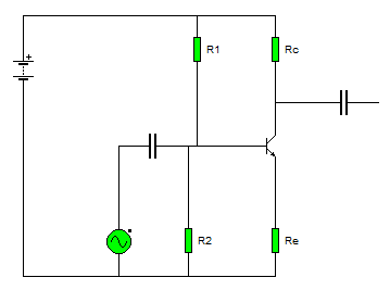
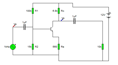
Common Emitter Amplifier
The last amplifier that we looked at was an emitter follower or common collector amplifier, that's a device that amplifies current, whilst leaving voltage unchanged, we used that to boost the amount of current available from a low power source so that we could turn on a light.

The amplifier that we'll be looking at now doesn't amplify current, it amplifies voltage.
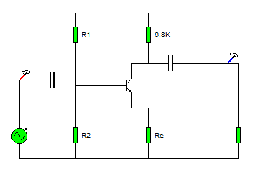
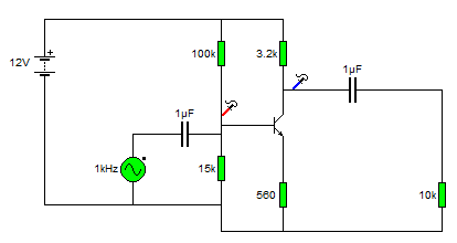
The first thing to do is introduce you to the circuit.

Firstly, lets break the circuit down,
The little round thing with the waveform shape in it is a signal source,

For this demonstration we'll set the output of the generator to a sine wave, with a frequency of 1KHz and we'll set the amplitude (size of the signal) to 1v.

This means that the waveform outputted by this generator is:
A nice curvy wave form, that is modelled by the math function sin(x).
It goes between +1v and -1v.
And it does this one thousand times a second (a complete cycle take 1millisecond -1ms.)

The next component we see is a capacitor, in the lesson on capacitors I talked about the capacitor acting like a storage tank for electricity, saying that you could charge a capacitor and discharge a capacitor, here we are using a different property of the capacitor, it's ability to block DC (direct current) signals, and allow AC (alternating current) to pass.

The reason that we want to use this is because we need to set a bias on the transistor so that it's working in a linear region, -don't worry about that for now, I'll explain more later, right now we'll look at the DC blocking capabilities of the capacitor.

When we use a capacitor like this it's called a coupling capacitor.

Coupling capacitors
The problem with the signal source that we have is that it's waveform is centred around 0volts.
fair enough the transistor will turn on then the voltage rises above zero volts, but when it's in it's negative half of the cycle (or anywhere in the cut-off region), the transistor won't be conducting at all. So we need to move the centreline of the wave form up so that it's centred around a positive voltage, that'll let our transistor work in a region where it's on a little right up to on a lot, (remember how we talked about the transistor as a variable switch? now we're going to use it as a variable switch.)

Before we introduce the transistor into the mix we'll look at how we get that wave form to climb up to a more positive voltage using coupling capacitors.

The diagram below shows some things that should be familiar to you from lab 1.

Ignore the capacitors and signal generator for now.
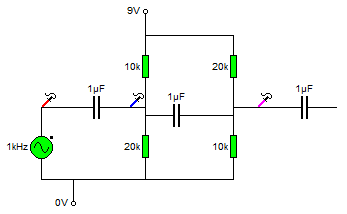
There is a positive voltage source (+9v) and a zero voltage source (0v) (just like the battery terminals.) And there are two resistors set up as a potential divider, followed by two more resistors set up as potential dividers.

Using the maths learned in Lab 1 we can see that the voltage at the blue probe is 6v, and the voltage at the pink probe will be 3v. -remember Vout = (Z2/(Z1+Z2)) * Vin)?

So we know that there is a DC voltage of 6v at the blue probe, and a DC voltage of 3v at the pink probe.

(now we'll include the capacitors and signal source again).

The resistors used are significantly high enough to not interfere with the source when the AC signal is introduced.

Reading from left to right.
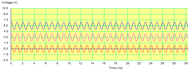
The first red probe, measures voltage a +/-1v centred around 0v.

The capacitor then blocks any DC voltage going to, or from that point in the circuit moving onto the next point, (blue probe).

If there were no DC component here we'd measure +/- 1v centred around 0v, however, the potential divider here means that there is a 6v DC voltage at this point, so that +/-1v is superimposed on this 6v source. meaning that the wave form is now alternating between +7v and +5v (+/-1v centred around 6v).

Moving a little further on there is another capacitor that stops this +6v DC component from moving to or from any other part of the circuit. Here we reach the pink probe.

Now the wave form has had all it's DC component removed and is once again 0v +/-1v.
but our potential divider has set a DC voltage of 3v onto this part of the circuit. So once again the AC voltage is superimposed on the DC voltage giving a wave form that's +/- 1v centred around 3v (+4v to +2v).

Here is what the wave forms are looking like at each part of the circuit.


Biasing
I suppose that the first question that needs to be answered is Why do we bias amplifiers. I gave a pretty poor description above about the fact that it doesn't turn on on the negative half cycle of the input wave, (and that is true).
but to answer the question properly again we're going to need to look at the data sheets for the component again.

Lets take a really simple (and now really rather old transistor, the BC108).

http://www.datasheetcatalog.org/datasheet/MicroElectronics/mXuvuyv.pdf

As before there are a couple of important things to look at in the data sheet.

The first is Base - Emitter voltage (Vbe) you can see that this is 0.6v

Next look at the gain value of the transistor, (this is called hfe) this is (for group A components typically 170).
this large hfe value means that we know that the collector current is much much larger than the base current.

so Vbe = 0.6
Gain = large
Ic >> Ib
Ie = Ic + Ib

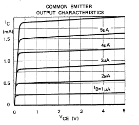
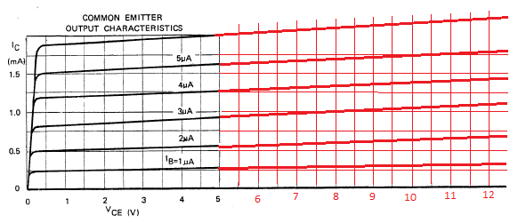
You'll find a graph in that data sheet called "output characteristics",
The output characteristics these define the voltages that you need across the device to make it work in a region called the linear region, this is the region where the device is going to amplify small and large signals equally without distorting either.
There are several lines on the device, all are in a shape that goes up at the start, and has a sharp knee, then settle into a straight line, the different line correspond to different base currents.

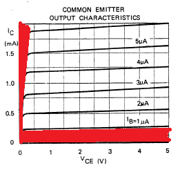
On the graph below I've marked two areas in red, you want to stay out of these regions because either the transistor is off or behaving in a non linear way (very on), (the one closest to the X axis is the cut off region) and the one closest to the Y axis is the saturation region.

The first thing that you're going to need to determine is the Resistor RL, this is the load resistor for the amplifier,

First, you're going to need to extend the graph so that we can see it working inside the voltages that you're working with, (the x axis only goes up to 5v, and we're going to use a 12volt supply).
(I'll assume by now that you've murdered an ATX power supply and therefore have a 12v supply (and are no longer relying on 9v batteries).

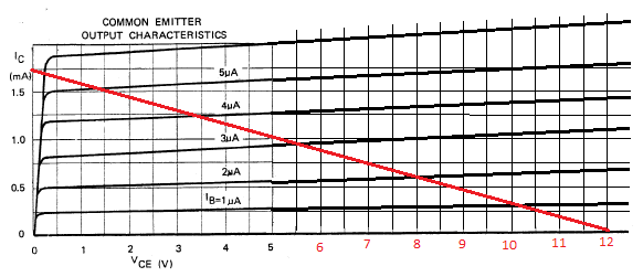
Now you need to draw line on the graph between the point the you want to set as ICmax, (on the Y axis, and your supply voltage (Vcc) on the X axis.

Set your ICmax somewhere below the highest marking on the chart, I've chosen 1.75mA

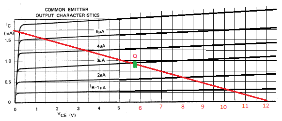
This new red line is called the DC load line, and in the middle of this line is a point that's at the middle of the linear operating region of the amplifier, this is the quiescent point, or Q point.

You can see the green dot in the middle, set at around 5.8v (you might also be realising that this is not an exact science!)
Right... so what we know now is:

Ic(max) = 1.75mA
and Vcc = 12
Vce(q) = 5.8
Ic(q) = 0.9mA

We need to make a decision now as to what we want the voltage of our emitter to sit at, some guides suggest splitting the voltage equally between the Rc, Rb and the transistor itself, however, I think that setting Vre as 1v doesn't seem like a terribly bad thing to do! -you could chose a different value.

To find a value for Rc
We use the forumla

Ic(max) = (Vcc - Vre)/Rl

0.00175 = (12 - 1)/Rl

Which works through to give us the equation
Rl = 11/0.00175 = 6285
The closest standard value is 5.6K or 6.8K

It'll be perfectly fine to use a 5.6K this will increase your IC(max) value, but you're still far below the absolute maximum rating given on the first page of the data sheet. the higher the voltage here the more restrictive you're being on the input signal voltages that could be used before the amplifier clips the signal.

The current gain of the transistor we know from the data sheet is 170

the gain is the value of the collector current, over the base current

hfe = Ic /Ib

hfe = 170 and Ic = 1.75mA
Therefore Ib = 1.75ma / 170 = 10uA


Given that we now know the values of Vre, Vbe and Ib we can start to set the bias of the base leg of the transistor.

To find the value of R2 we use the following formula.

R2 = (Vre + Vbe)/(10 * Ib)

R2 = (1 + 0.6)/10 * 0.00001)
R2 = 1.6/100 * 100^-6 = 16000 -15k is the closest standard value

and we can also figure out the value for R1

R1 = (Vcc -(Vre + Vbe))/(11*Ib)
R1 = (12 - 1.7)/(11*0.00001)
R1 = 10.3/0.00011 = 93636 - 100k is the closest value


Now we need to go about setting that emitter resistor Re.
We calculate this using Ohms law
We know that the emitter current is the sum of the base and collector current
Ie = Ic + Ib
Ie = 1.75ma + 10uA
Ie = 1.76mA

We know that Ohms law says V/I = R

Vre / Ie = Re
1 / 1.76mA
1/0.00176 = 568 Ohms (and the closest standard value is 560Ohms)

Earlier we talked about coupling capacitors,
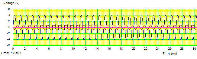
on that last amp circuit you'll see red and blue probes, this is what the signal looks like at those points.


Input vs. Output
Finally, let's move our probes to measure the input and output signals.


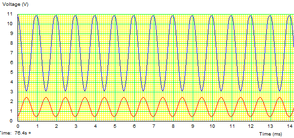
Look closely at that chart.

The red line is the input signal, and the blue line is the output. We see that the blue line is much bigger than the red line, but also notice that as the red line is going up, the blue line is going down.
This amplifier has switched this signal upside down.

This type of amplifier is called an inverting amplifier.

Gain
The gain of am amplifier is its output divided by its input.

remember the current gain of the transistor was the collector current, over the base current.
(actually it's emitter current over the base current, but since the gain factor is so large we assume that Ie is just about equal to Ic)

The voltage gain works the same.
The input voltage is +/-1v, (e.g 2v).
and the output voltage swing is +/- 4v (eg 8v)

So the gain of this amplifier is 8/2 = 4

The signal coming in is made 4 times larger.

Thursday, August 11, 2011

Electronics Lessons: The Transistor Simple Circuits (Lab 2)

So in the last lesson I talked about the transistor, I talked about how you could turn the transistor on to a fully conducting state.

I also mentioned that transistors could be used as current amplifiers.

You'll use a current amplifier when you need a little more power to switch on an output than that output can supply.

We discussed before how the transistor was off, and how it could be turned on.

So, lets make a device that puts a light on with the presence of a voltage, even if that voltage source doesn't have the power (current sourcing capability) to light up the light itself.

In this tutorial we're interested in two areas of the transistors output, because we're going to use the transistor as a switch we'll either have the transistor in the cut-off region (off), or the saturation region (on) of it's output characteristics. (There are the areas marked in red in the chart below).


The Circuit
What we do is connect the input to the base of the transistor, we use a resistor to ensure that not too much current is pulled from the voltage source that we're detecting.

We'll also put a resistor between the circuit voltage source, and the transistor to limit the current being drawn from the source.

Our light will be an LED, we're expecting that the voltage going to the LED will be 5V at most, but as little as 3v so we look at some data sheets for LEDs and we find that the there are a couple that we can't use, (some have Vmax as 4v), and others will tolerate a higher voltage, but won't light with only 3v.

Eventually we come across the L-53GD-5V made by Kingbright

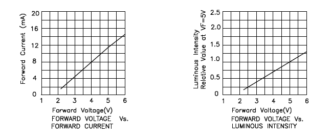
It has the following characteristics.


So we can see that it'll be on, and bright at 5v, and it will turn on, (though only be half as bright) at 3volts, (we're interested in sensing 5v Logic levels and 3.3v Logic levels right?)

Elsewhere in the data sheet it tells us that the maximum current is 17mA
We know that our greatest voltage going through the LED will be 5v
So we use ohms law to determine the resistor needed.

5/0.017 = 294

So we really want to make the total resistance between the supply voltage and the indicator LED around 300Ohms
In case you're interested

3.3/300 = 0.011 or 11mA available for the 3.3v logic level to light the LED.

I say the 3.3v, remember this is a current amplifier, not a voltage amplifier. The voltage is going to remain the same as what's going into the transistor base.
Anyway, at 3.3v the LED only draws some 6mA, so there is plenty of current available. (and that 11mA is below the devices max draw of 17mA

Schematic
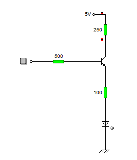
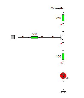
Here is the schematic of the circuit.


And here's what happens when a logic level of 1 (+5v) is applied to the base resistor


When the circuit is on it pulls around 6ma from the logic source, and the current going through the LED is about 14mA.

Stay tuned to see this idea scaled up!

Monday, February 05, 2007

Fag Pack amp


well I made the fag pack amp...

not that it worked... Damn Maplin... looked up all the parts online, went to the shop expecting to be able to just grab the things off the shelf only to be told... "I'm sorry they are web only orders"...

not to be put off, I had a quick flick through the catalogue in store... decided that my design would have to be abandonned, and went about getting parts for a stock amp using the simple suggested design in the catalogue... (the reference circuits).

it's only one fucking IC and a handful of resistors and caps... how could it possibly fail...

I don't know but it did!

ahh well I'll have another go sometime in the near future when I get a bit more spare time.

Why is this tagged scavenging? well the speakers for the amp were from a laptop they fitted nicely into the cigarette packet leaving plenty of space for the battery.