Showing posts with label Solidoodle. Show all posts

Monday, April 22, 2013

Making a new hotend heater

Annoyingly my replacement hot end for my solidoodle has failed again. it did last a lot longer than the original hot end that came with the machine, but it was fairly obvious that it would fail again.

The mode of failure is that the nichrome wire is getting too hot and melting through the Kapton tape, this is turn is making short circuits, and reducing the heater resistance, this is making more current flow, and the power to the heater is increased, I'm seeing a lot of max temp reached where the hotend starts to peak well in excess of the max temp permissible, (the max temp is to protect the peek)

But also the sudden rushes of current cause cause the power supply to stall, I've had steps being skipped, sometimes I've had axis appear to just re-home themselves, so instead of a single layer skipping, the entire model will just move two inches to the left have way through a print.

So this time I'm going to go all out and create a new hot end.

I'm going to base my design on the Jhead style heaters, with a block close to the nozzle, but instead of using a resistor I've decided to use a small ceramic heater.

Instead of tying my heater and barrel to the nozzle (which I may want to change to have greater or smaller nozzle widths) I'm going to stick with the M6 barrel of the solidoode, I'll stick with the removable nozzle, and I'll make a heater that can be screwed on and off just like the heatcore design could.

To start with I've located a 40w ceramic heater online that comes in a 23mm long 6mm diameter tubular package.

This will be my heater.

My block that will be used to store heat will be aluminium, (it's easy to acquire, relatively cheap -at least cheaper than brass)

The block will need to be at least 20mm wide to accommodate the 23mm heater, (it will not matter if 1mm sticks out either side -and this will help keep the wires away from the hot metal.
the block will be 10mm thick, this should mean that there is 2mm either side of the heater,
this will also allow for a 3mm hole to be drilled to install a grub screw to hold the heater cartridge in place.

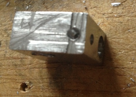
The heater will be 2mm from it's opposite side of the block, and 2mm from the barrel of the machine, the barrel is 6mm wide, here will need to be at least 2mm on the opposite side of the heat block, (therefore the heater block must be 20mm x 10mm x 18mm, the most convenient size is 20mm x 20mm x 10mm)

Lastly the thermistor must also be installed in the printer, and must be thermally bonded reasonably well, to achieve this I plan to use heatsink style thermal compound and a second grub screw to ensure good contact.


Materials needed,
1 Aluminium block, (20mm x 18mm x 10mm) -I cut my block from a length of bar that was 20x10 x 2000mm
1 heater core, I bought mine as a 40w heater, but the measured resistance is actually 4.2Ohms, so it's actually a 34W heater.
3 grub screws I'm using M3 x 3mm
Thermistor -I'm re-using my original.
electrical connector - I'm re-using my original

Tools needed (at a minimum)
hacksaw -I'm using a B&Q value junior hacksaw -that cost 99p!
Drill
5.5mm Drill bit
2.5mm drill bit
6mm drill bit
M3 Tap
M6 Tap
Ruler
scribe for marking

so, here's the process.
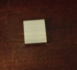
First mark 18mm from the end of the bar
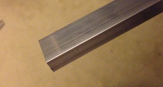
then cut off the aluminium block
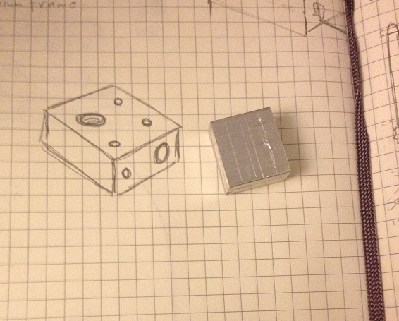
now you need to use a scribe to mark where you want to drill
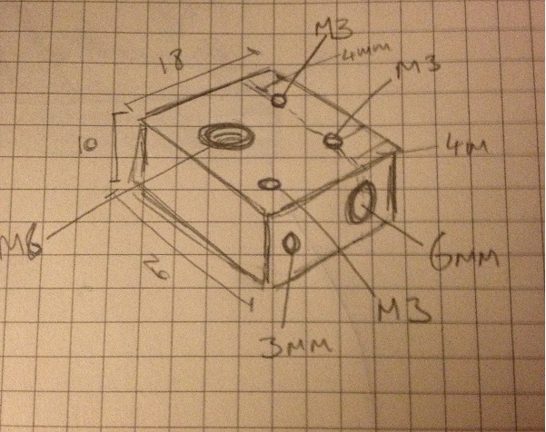
(the measurement that is missing here is that the M6 hole is centred 9mm from the far edge)
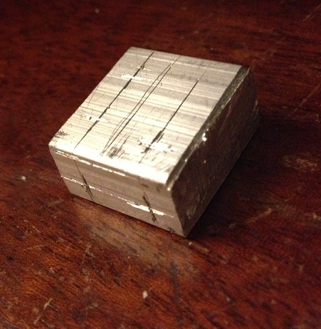
first drill the long hole through the block, start with a 3mm hole and then enlarge that to a 6mm hole
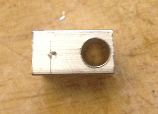
then drill a 2.5mm hole next to that, about 5mm into the block
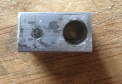
now drill a 3mm hole and enlarge that to a 5.5mm hole (ready to be tapped for M6) in the face of the block
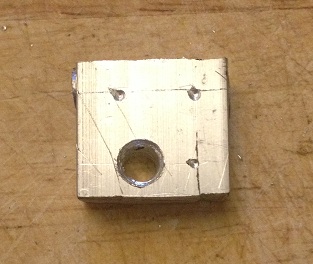
test fit the heater to make sure it fits
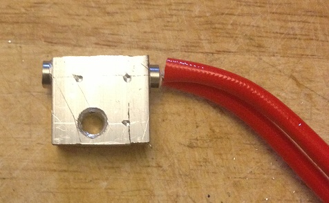
now using a 2.5mm drill bit drill three holes in the top face of the block.
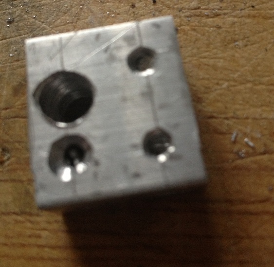
unfortunately my drill bit broke inside the last hole, so I put a different hole in the side instead -the drill bit is still stuck in the block sad

now you need to use the M3 tap to create a thread on the two 2.5mm holes that are drilled through to the 6mm hole, and also in the final 2.5mm hole, (this should be on the top, but mine is on the side thanks to the broken drill bit)
Then you need to use an M6 tap to create a thread on the 5.5mm hole that goes through the block.
now we come to assembly.
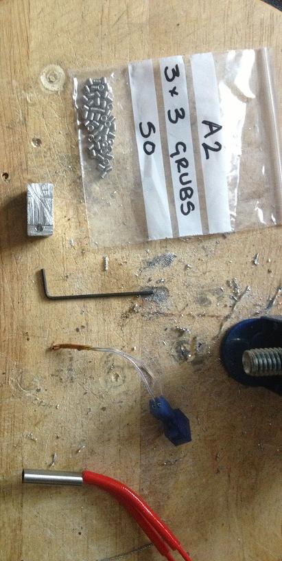
the heater slides into the 6mm hole.
the thermistor slides into the 2.5mm hole.
the thermistor is secured with an M3 grub screw.
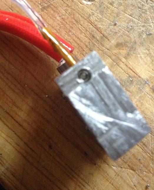
and the heater secured with two more grub screws
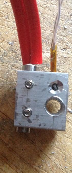
Now I've pulled the whole connector off the original green heat core wires, and attached it to the new red heater wires.
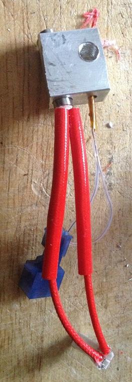
You need to remove the extruder from the machine, (the block catches on the carriage if you don't remove it to turn it)
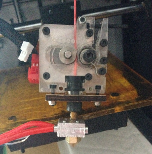
then you can screw the new heater onto the machine and replace the nozzle.
after that the only thing left to do is re-mount the extruder, re-connect the wires and start printing!
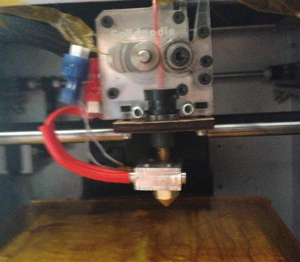
The heat-up time is more or less exactly the same, and the stability of the heater is actually probably a bit better than the original heatcore, (looking at the graphs in RH)

Monday, February 11, 2013

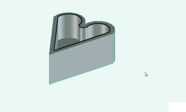
Craft: A heart shaped box for Valentines day

As I mentioned in the post when I http://ah-screwit.blogspot.co.uk/2012/11/the-solidoodle-has-landed.html got the solidoodle that I'd made a heart shaped box.

I thought that as valentines day is soon that I'd go through the design steps for the box in Creo Elements so that you can make your own.


The first, (and perhaps most important thing) is that there is no grid function in creo elements, there is a snap function, but there doesn't seem to be a way of showing a grid on the work plane that you're currently editing.

This means that I end up drawing construction lines all over the place.
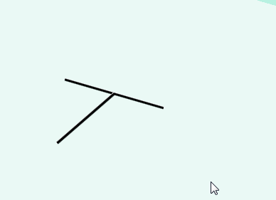
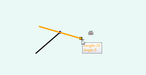
So, your box should start with a line.

20mm long,
Then in the line of this line, draw a line 20mm long perpendicular to this

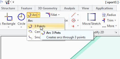
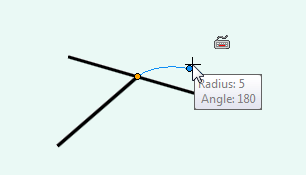
Next you need to select the 3 point Arc tool

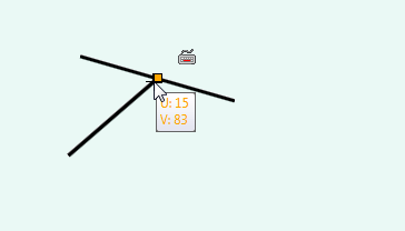
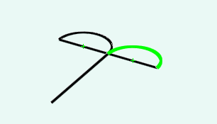
Click at the junction of the 2 construction lines, and then at the end of the first line, now move your mouse away from that line and see where the arc is, since the diameter of my "circle" would be 10mm, I need the radius of my arc to be 5mm


This is then repeated on the other side,


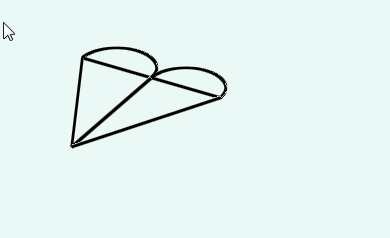
Finally the straight line tool is use to finish the rough heart shape connecting the arc to a point at the bottom.

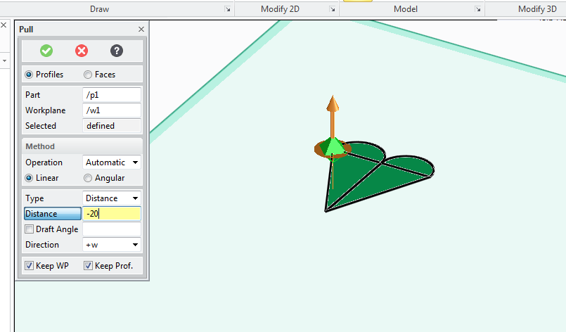
I then use the pull tool to make the box 10mm deep.

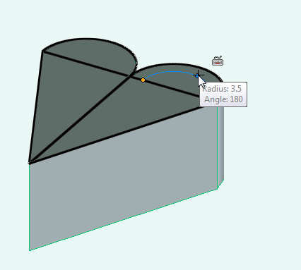
Then start again with the arc tool, this time make the arc start 1mm in from the egde and at leach side, and the arc 3mm in radius.

Then join the two arcs together at the point


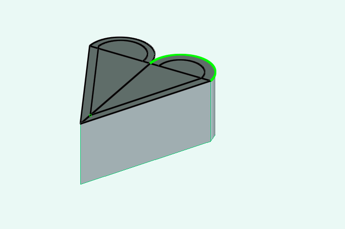
Then connect the the new arcs together with a new arc (where the round bit points downwards.

Finally remove the heart on the outside


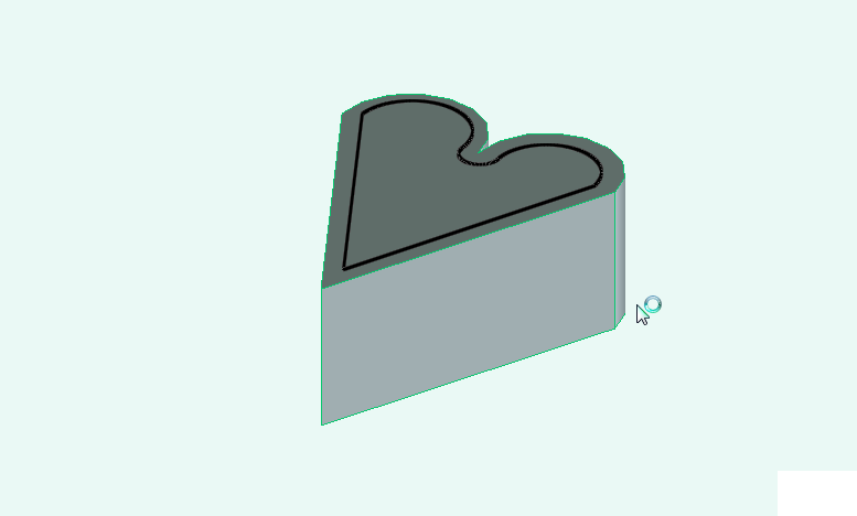
Now use the pull tool again to sink the top of the box 8 mm into the box.


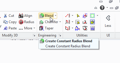
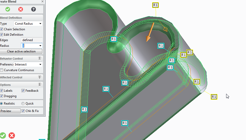
Finally use the blend tool,

Set the radius to 1mm, and click on every sharp corner to smooth out your model.

Export and print your model as appropriate

I also made a lid for my original box.


You can get the STL from the post I made in this thread of the solidoodle users support forum.

http://www.soliforum.com/topic/468/heart-shaped-box/

Monday, February 04, 2013

Experimenting with printing surfaces

So I decided that I'd experiment a bit with printing surfaces.

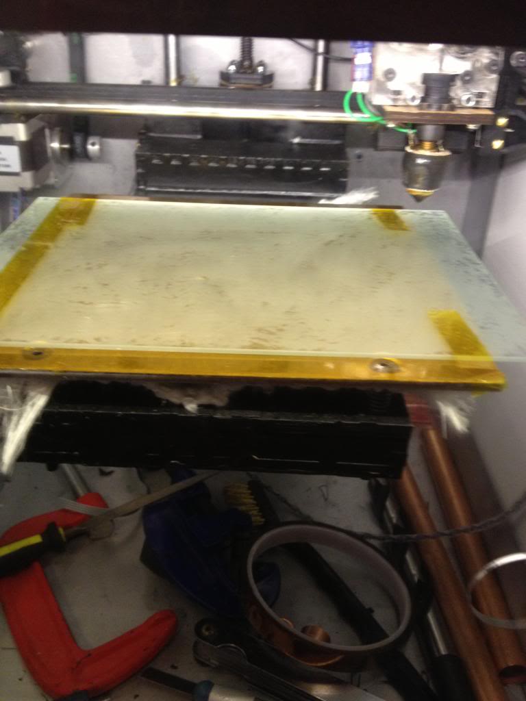
I've got my glass printing surface, and that's working great, but I'd still stretching Kapton over the top of it.
The Kapton tapes job is to provide a texture for the ABS plastic to stick to as it's extruded.

There have been many reports that people are not using Kapton, (which tends to get damaged over time) and are instead getting their textured surface from a film of hair spray that can be easily applied and easily cleaned off of the print bed.

Given that the point of both the Kapton and the hairspray is to provide texture I wondered if using a piece of frosted glass would allow me to have a durable print surface that I wouldn't need to keep applying, and that wouldn't wear out.


I used some glass etching cream, and painted it liberally over the surface of the glass, and left it for 15 minutes, the glass plate was then washed.


I secured the glass plate to the print bed with 6mm Kapton tape looped around the bed, and turned the bed on.

I realise that the glass is going to be at a cooler temperature than the aluminium bed that it sits on, so the print bed won't be the same temperature that the aluminium bed normally gets to.

To compensate for this I turned the temperature up in the pronterface print software and measured the glass surface temperature using a thermo couple.

When the glass was at temperature I attempted to print on it.
I found that the ABS did not stick at all.
despite what the common understanding or rumour says, it appears that Kapton tape provides a bit more than texture for the plastic to stick to.

Monday, December 31, 2012

Making door signs with a 3d printer.

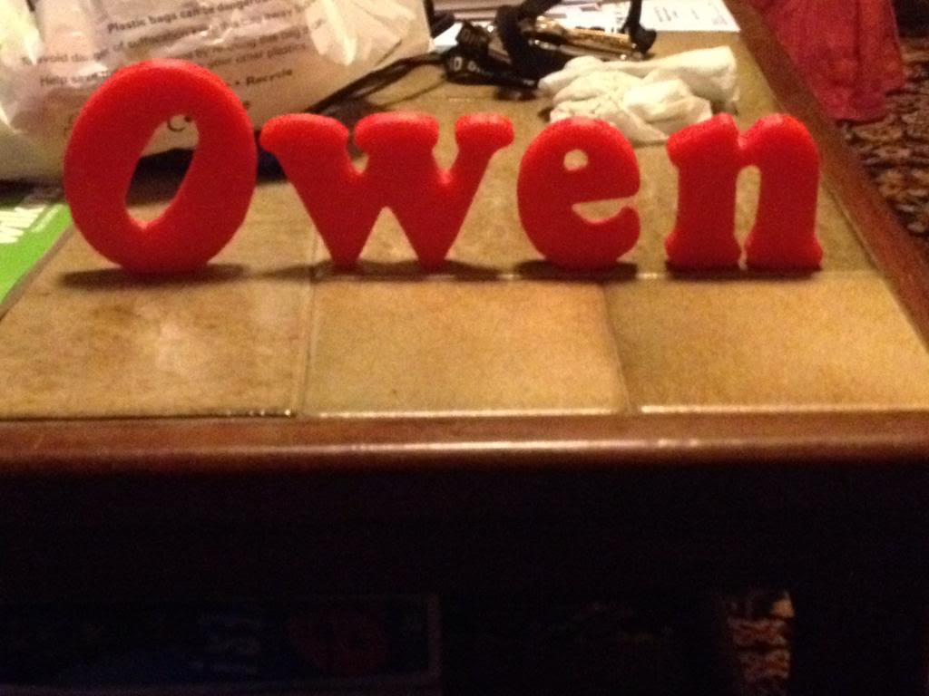
This was a little bit of fun to give my nephew something nice for Christmas. I thought that it might be nice if he got a nice sign for his bedroom door with his name on it.

Rather than go out to the garage and get busy with the jigsaw/sandpaper and paint like I once would have I decided that I'd have a go at printing some letters that could be stuck to a door.

So this is a step by step guide on how to create letters and a door sign, from design to creation.

Modeling
First you're going to need 3d modelling software, this blog post will explain how to use the Creo elements software since that's pretty good and free.

Open the package, as before you see your work plane and nothing else,
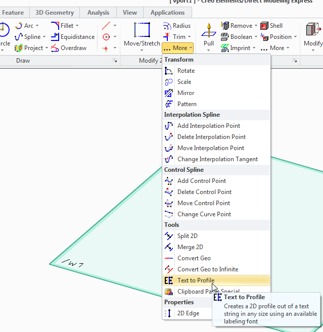
in the 2d toolbox click on the more button, and then select "text to profile" tool.

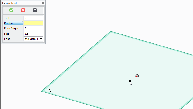
A box will now appear where you can enter the letters that you want to print.


As an example I've put the letter a
Now you press the position button and select where in the work plane you want the letters to appear.
(click somewhere in the middle)

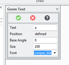
Now you need to define the angle that the letters will be at (zero is probably fine!) the size, -I want them large for sign so I choose 100, and the font.

I've chosen cooper black as the font. it's not the worlds fanciest font, but it is pretty good for printing, there are no weird angles etc no parts that will end up impossibly thin or unprintable.

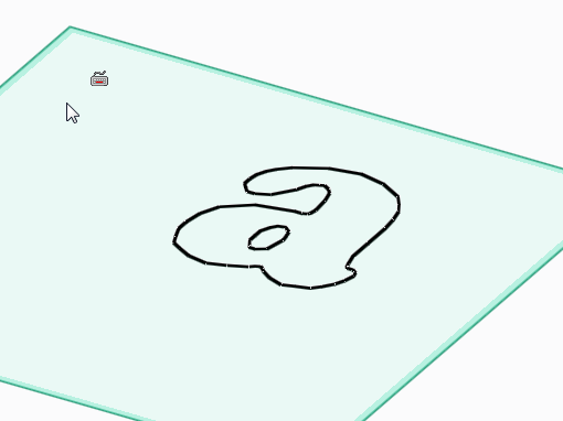
Once the letter is on the page we're going to need to give it some depth.

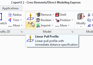
So use the pull tool:


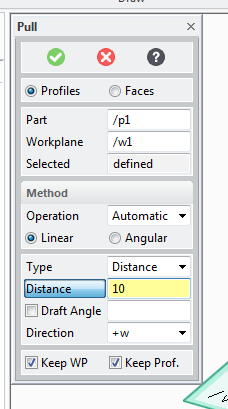
And select the pull width to decide how fat you want the letters to be:


Now delete the work plane ans select save.

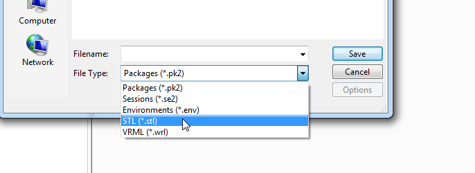
change the file type to STL


Now select to save All Objects using the button at the top, (that's only part 1)


type a file name and press save.

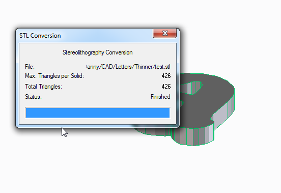
You can close the STL conversion box that appears.

Slicing
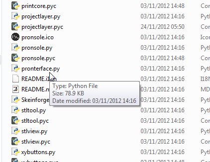
Now launch pronterface by running the pronterface.py file

you now need to access the model slicer.
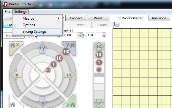
select settings, slicing settings

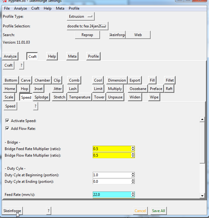
This opens a new window called skeinforge,
click on the skeinforge button at the bottom to open your model

Select your STL file and press open.

Now Wait...
...

...

Two new windows will appear, these describe in a colourful way how the models will be built. you can close these windows now.


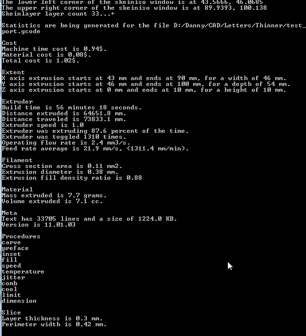
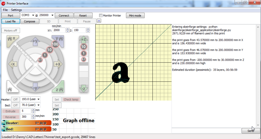
Now if you look at the python command line window that is open you can find some interesting things about your print that's going to happen, (like how much material will be used, how long it might take to print etc.

Printing

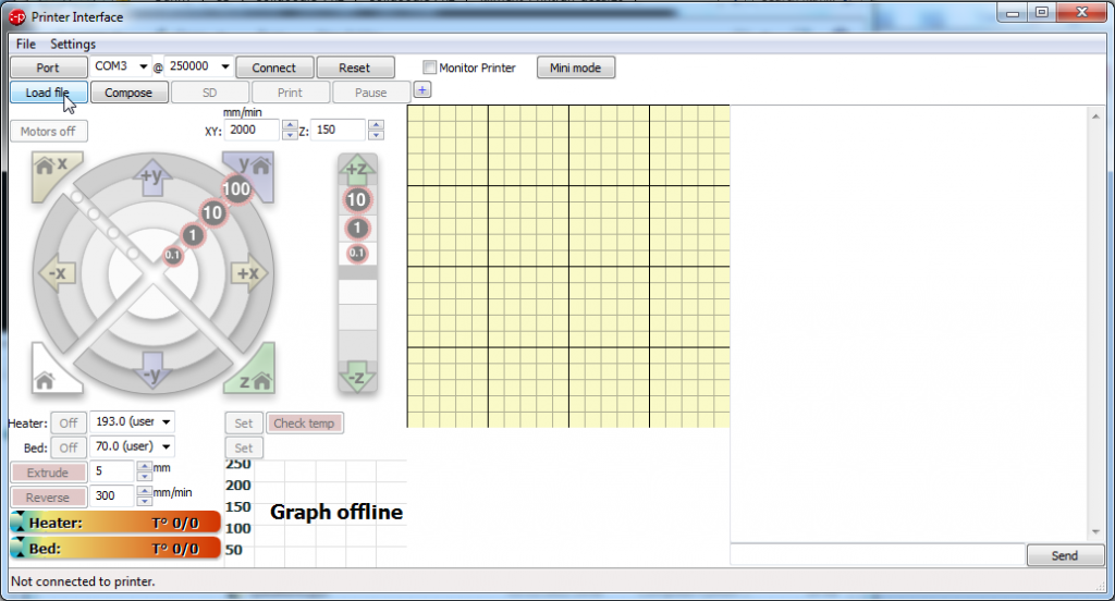
Now you should be looking at the pronterface screen again, select load file and open your file:

You now get a picture showing you how your file will look and where it will be printed on the bed.

Make sure that you have the correct com port set, and press connect.
Check the box that says monitor printer (in-between reset and mini mode)
now press set on the bed temperature.
watch as the actual temperature line ramps up to meet the target line.

When the bed has heated up, click set on the heater button, watch as the nozzle comes up to temperature.

When both the bed and the nozzle are at printing temperature then press the print button, then watch your printer make the letters for the door sign.