Showing posts with label bench. Show all posts

Monday, March 18, 2013

Breakout board for the Raspberry Pi


I've been talking a lot about my Raspberry Pi recently. That's because I've been playing with it a lot!

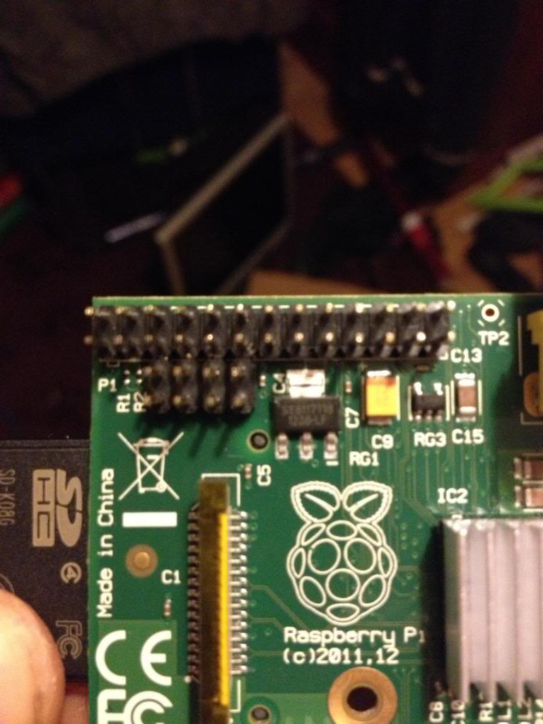
On the Raspberry Pi there is a row of pins called GPIO pins, the block of pins is called P1.
These are on most versions of the Raspberry pi the only  input/output pins available.

However on later versions there is a set of 8 pins next to P1 that have no pins soldered in.


So the first thing to do is remove the solder from this header (P5).

The plug for this header is supposed to be mounted with pins facing downwards. personally I don't understand why I'd want to have cables trailing from the top and the bottom of the boards, to me this seems like a crazy idea. I'd much rather have all my pins accessible from the top. especially when I use the mounting holes in this rev 2 board to screw the board down!

After removing the solder I've added 8 new pins to P5


Next there is a new pin header called P6 on the board, this is a set of pins that a reset switch can be attached to.


So now I need to get a plug to attach to these pins.

I started with a 44pin IDE cable.

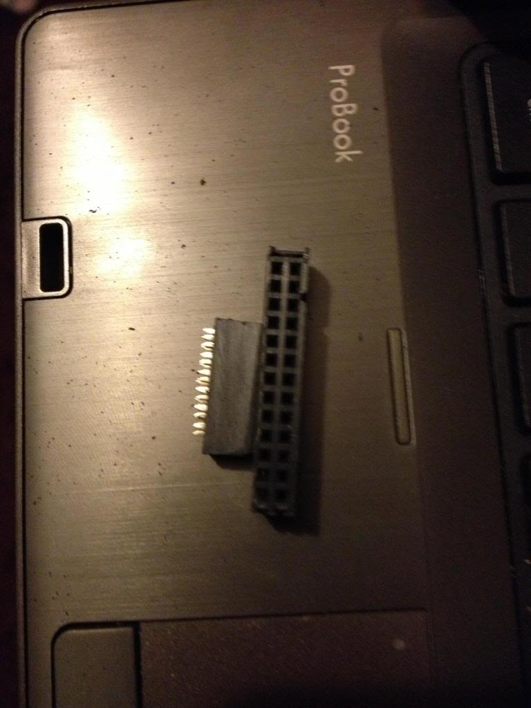
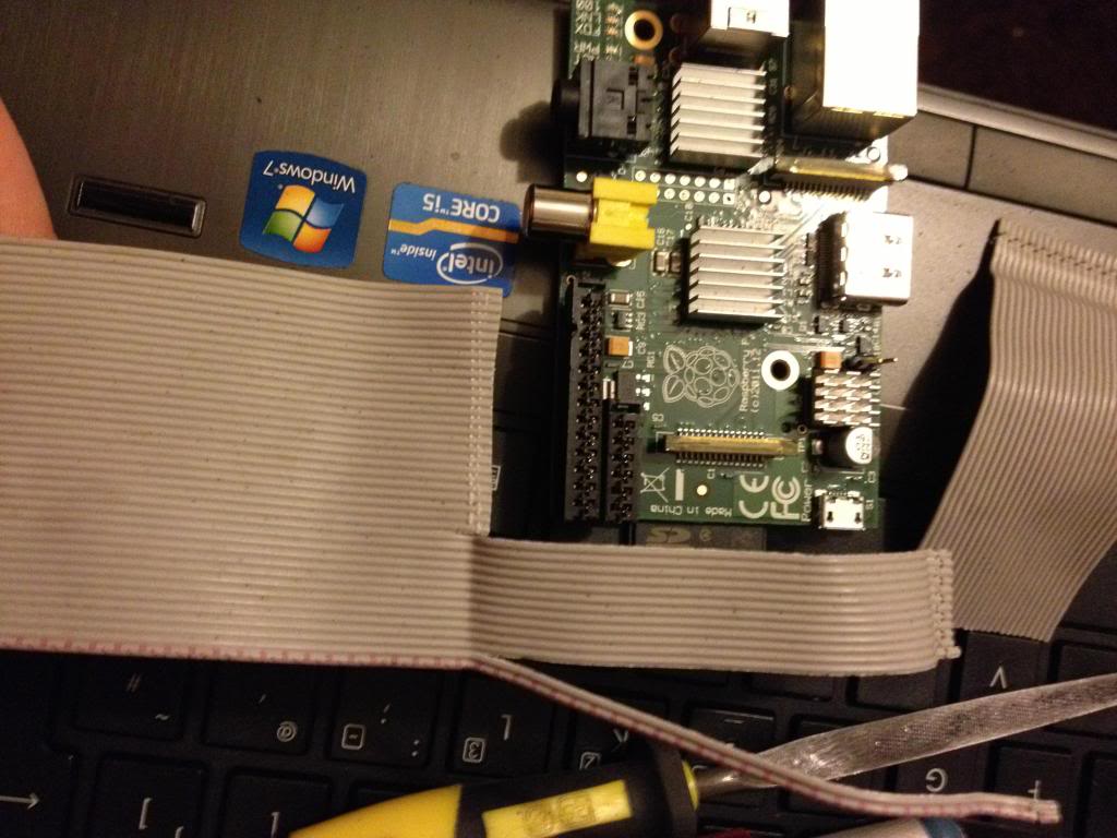
Start by removing the cable from the connector at one end, put that connector that you removed into connector P1. mark the first un-used set of holes, then using a utility knife cut through this set of holes.
This wastes 2 pins in the connector, but don't worry.


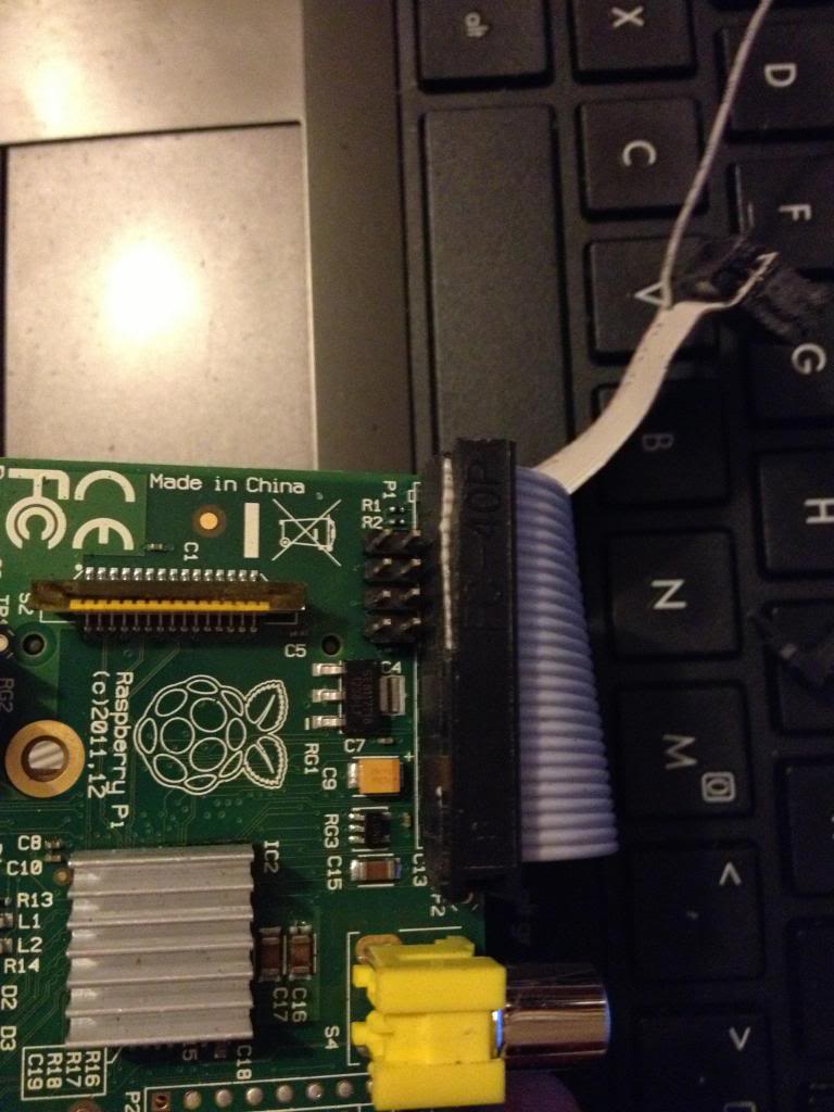
Now using a file or some sand paper you need to sand down the sides of the connector plug so that you can put these two plugs next to each other on the pins of P1 and P5 without them bending the pins.
This is halfway through,


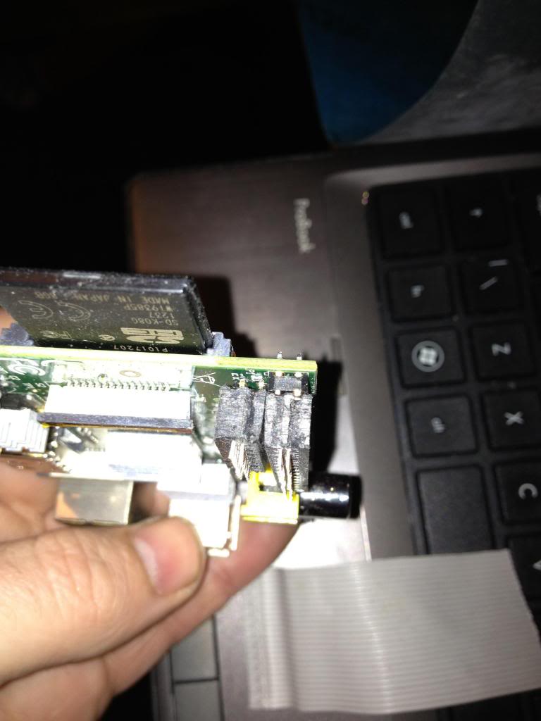
In the end the plugs should comfortably sit next to each other.

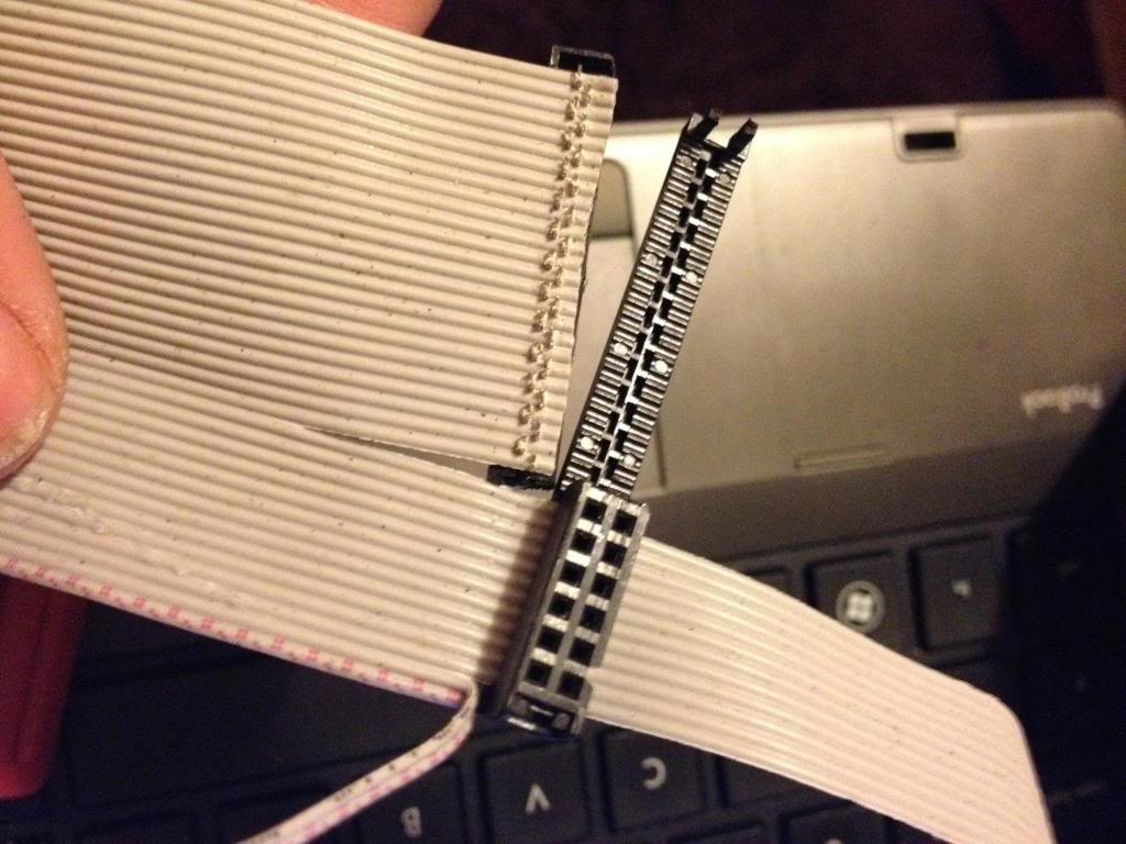
Next take the cable, and divide it to split the cable with 26 pins from end of the cable, lay this across the board and trim the first 26 conductors in the cable so that they are about 1 and a half to two board widths shorter than the rest of the cable, also split the first two conductors away from the bulk of the cable.


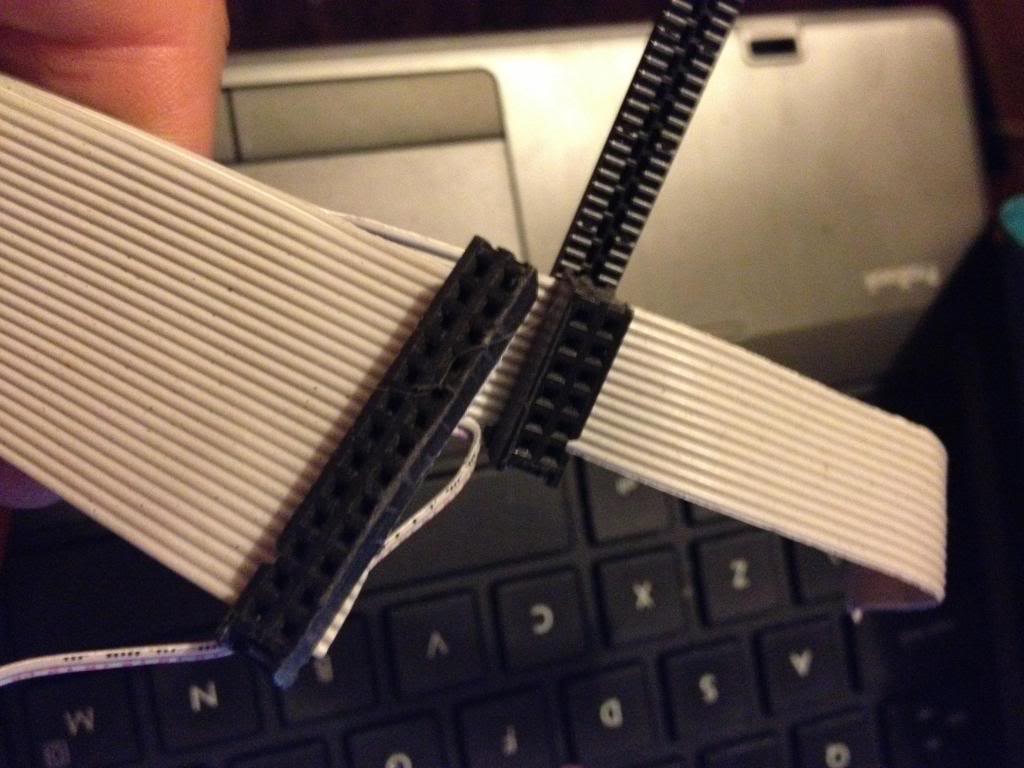
Now attach the larger half of the connector that was cut in two to the first 26 pins.


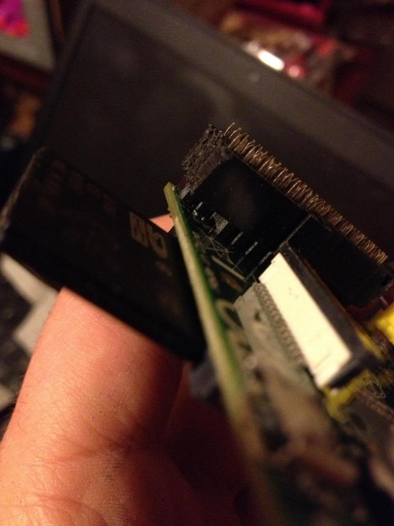
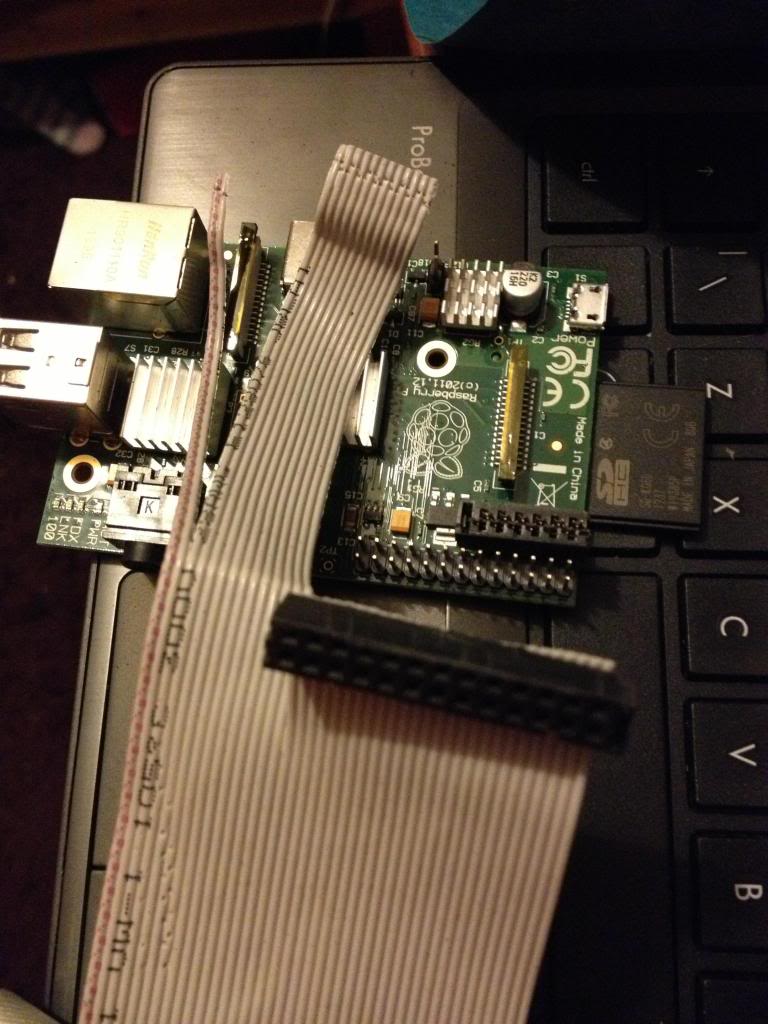
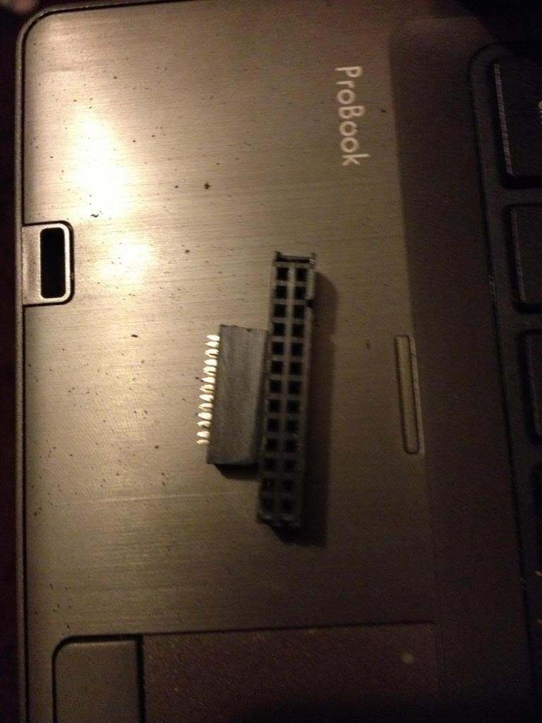
Next turn the cable over, and attach the smaller half of the connector to the remaining part of the ribbon cable, so that it sits diagonally next to the P1 connector.

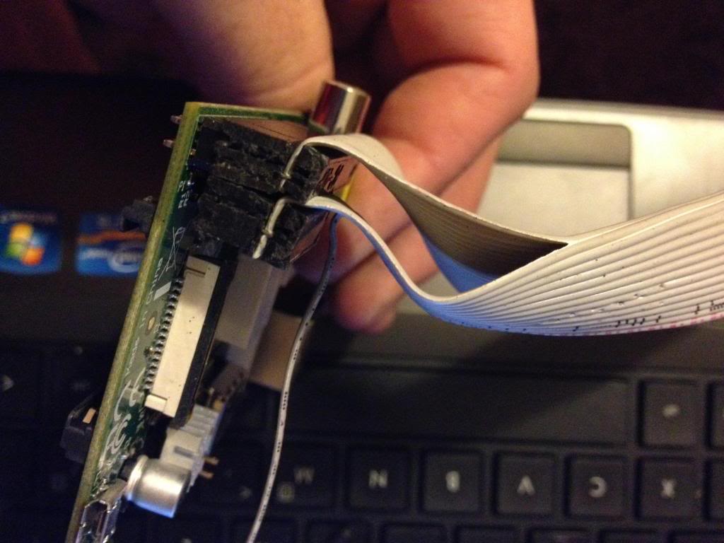
When you fold the cable over, the two plugs should sit next to each other in such a way that they will easily connect to the P1 and P5 headers, (obviously the sides of the connecttor previously sanded away to allow this fit must now face each other!)


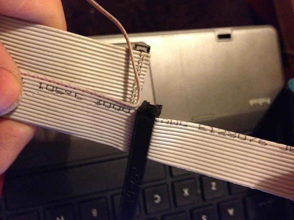
Next cut the cap for the plug and glue over the top of the cable to insulate the terminals that have cut through the insulation on the ribbon cable.

And ensure that both connectors can be attached at the same time.

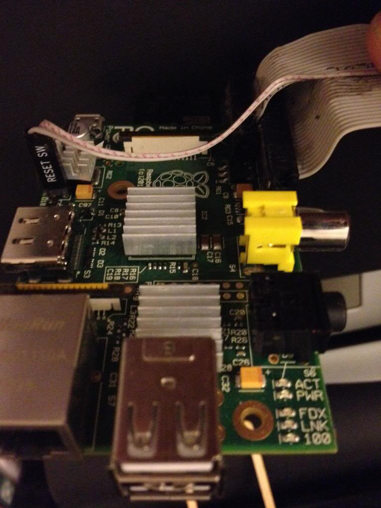
Finally attach a connector to the remaining two conductors in the cable and attach this to P6. I salvaged the connector from an old computer case to it says reset switch, shorting the pins of P6 resets the device so it is apt to use this connector.

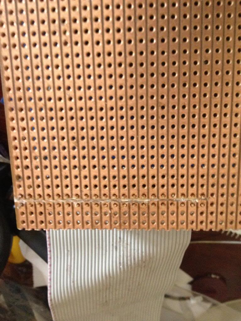
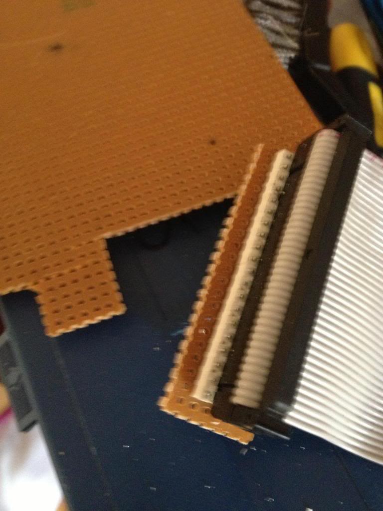
Next using some perf board cut the copper track on 22 rows ready to solder the 44 pin header.

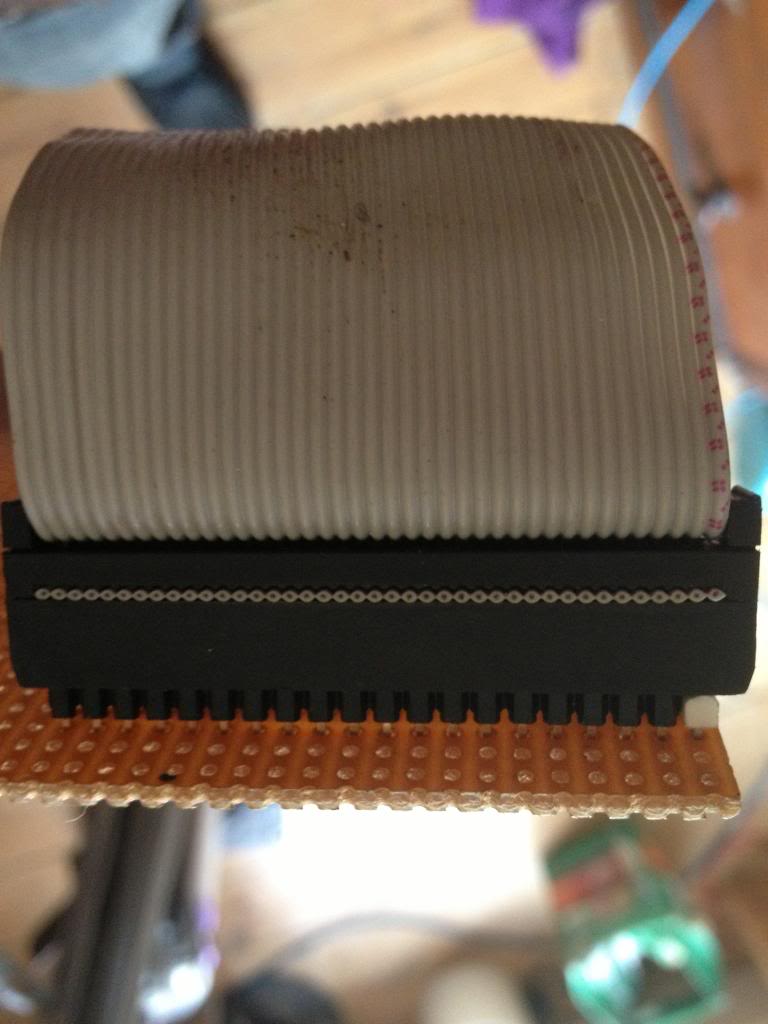
Now solder in the header pins to the perf board.
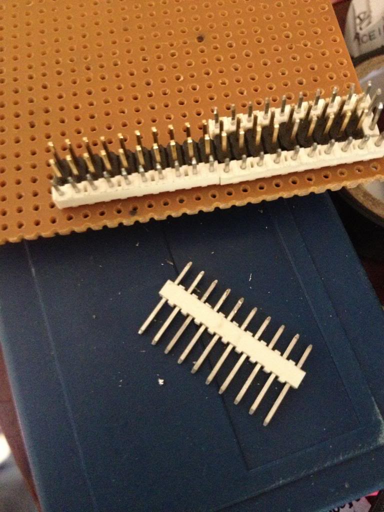
I've used a 42 pin connector which is black, and used a 2 pin white connector to mark pin 1.

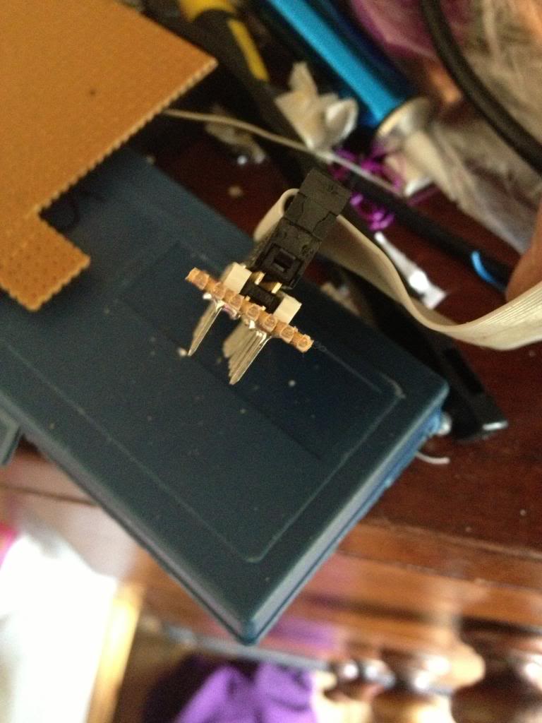
After soldering the cable header pins to the perf board you need to solder some pins that will go into the breadboard.

I used single rows of header pins next to the black connector header.


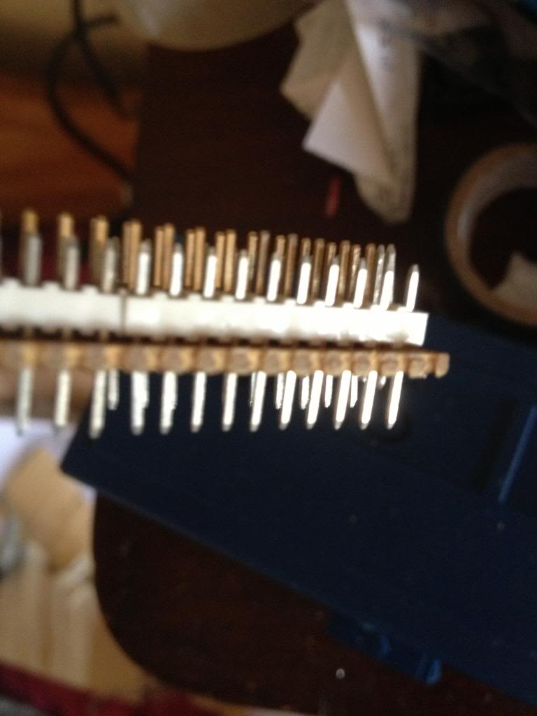
with the pins pushed down into the white block so that they protrude farther out the bottom of the perf board.


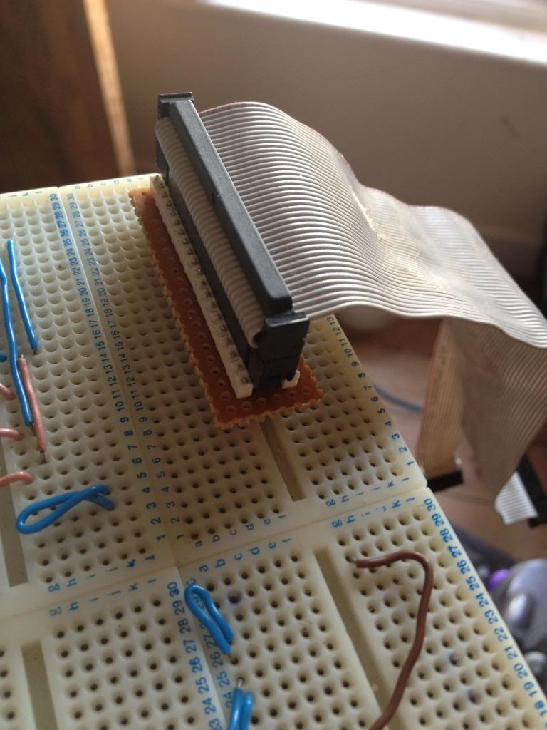
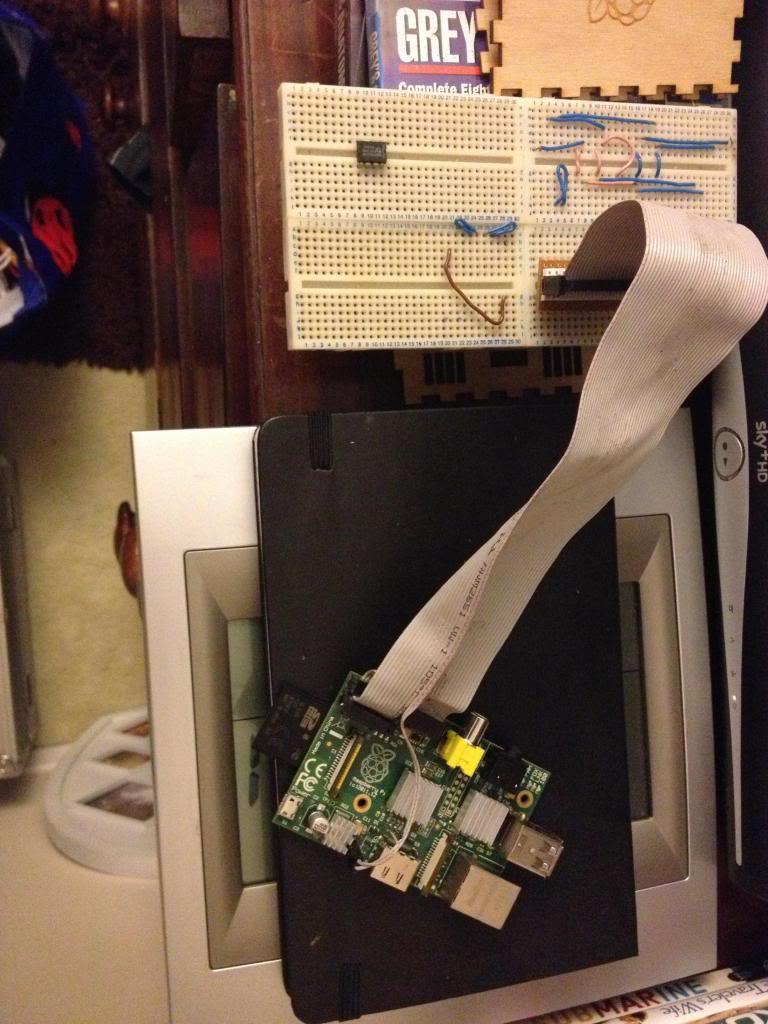
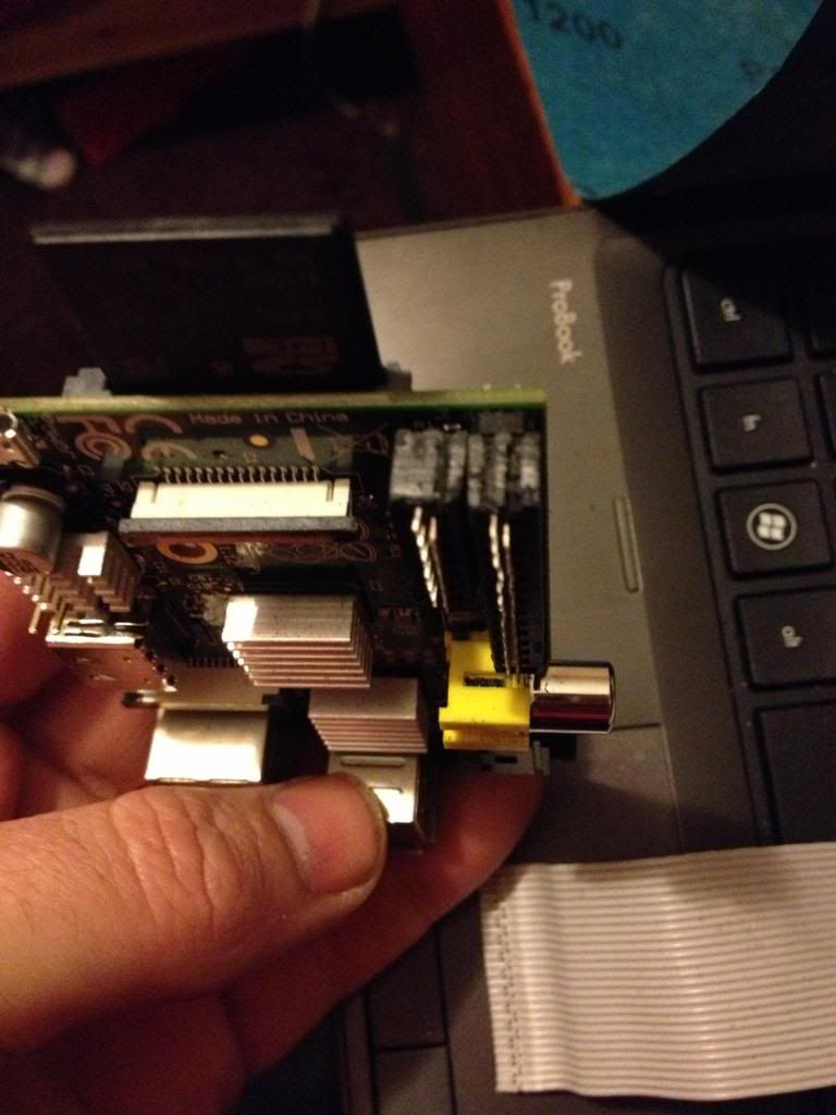
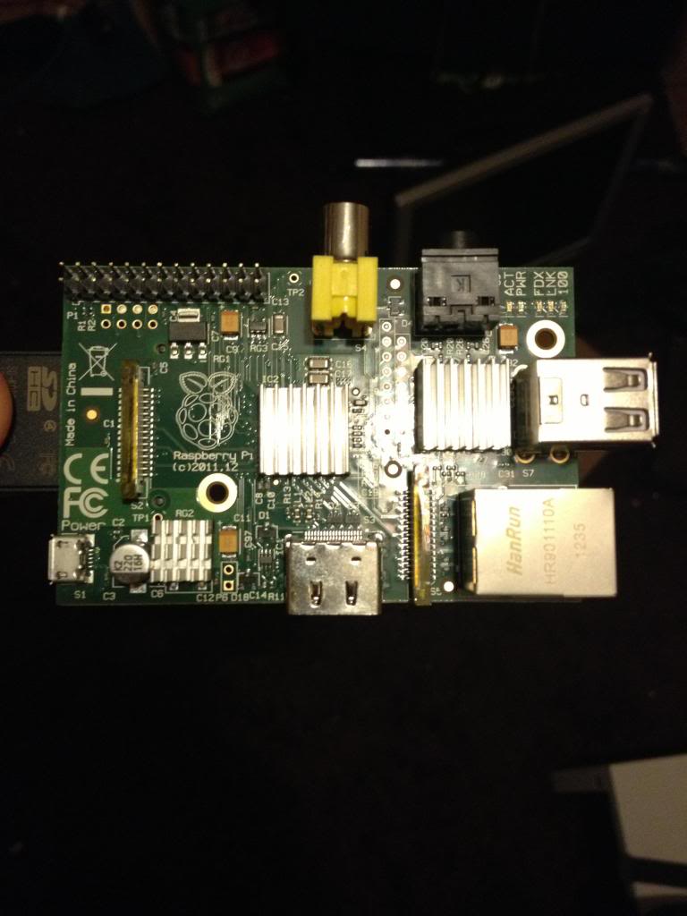
Finally the raspberry pi can be connected to my breadboard.


Monday, November 07, 2011

The Workbench/shop stock list

I've had enough of posting lessons for a little while so I'm going to post a little commentary.

back to a subject visited earlier in the year, the what tools should you buy list.

So far I looked at some very basic Electronics tools:
http://ah-screwit.blogspot.co.uk/2011/07/workbenchshop-stock-lists-electronics.html

As that post says, this was prompted by an article on Hack a day that was asking for comments on what are essential workshop stocks.

There was a £60 spend on the very basic electronics workbench and roughly £130 spent on woodworking tools (well you really should make nice cases for your projects!)

So of the original £600 budget I still have around £400 to spend.

During the course of introducing components I've suggested making a logic level indicator
http://ah-screwit.blogspot.com/2011/07/logic-level-indicator.html
This will save you a whole load of time making the circuit over and over and money, it's much cheaper to make this than to buy it.

So far on the list of stuff that you really should have in your workshop/workbench we have:
multimeter
soldering iron
Iron  stand
breadboard/choipping board/work surface protector
solder sucker/braid
breadboard
Clamps
Saw
Tape measure
Square
Marking Tools
Hammer
Punch
Chisel
Drill
Drill bits
Screw drivers
Safety Gloves

So lets start adding to that list.
By now you must have figured out that there are a few tools that are rather specialised, (solder suckers can only be used for sucking up molten solder) whilst other tools seems to be able to complete a variety of tasks with no ill effect. -as well as being able to solder a soldering iron is also a really good tool for burning wood, (that's if you're into creating wood burning drawings.

I've realised that there is a pretty essential item missing from the list.
Pliers
A decent set of pliers will include both needle nose and bull nose pliers.
If you're doing Electronics then you'll want a small variety, you'll also want a set of side cutters.
If you do bead craft then you'll mainly be interested in needle nose pliers, and side cutters.
Large work (and metal work) will likely require larger pliers.

A lot of needle nose pliers and have wire cutters built into them, and can also be used for holding nails as you begin to hammer them (saving your fingers!) three uses in a single tool. you should definitely get that!
A set of small pliers
http://www.maplin.co.uk/5-piece-miniature-plier-set-31557
this 5 piece set has bul nose, needle nose, end cutters, side cutter and curved needle nose.
£12.99 can't go wrong.

I think that takes care of all the change from the first £200 and gives you a pretty full tool box capable of working with both wood and electronics.

But lets look at expanding that...
As much as when you're starting out you clearly won't just spend £200 right off the bat on new stuff for a hobby. that list is very far from an exhaustive list of the kind of stuff you;re going to want to have around when you start to get seriously involved in the (very rewarding) world of DIY stuff, or hobby making and fixing.
now we'll start looking at some more specialist tools, these are the kind of non-essential stuffs, but also the high price items, this is where the money starts to disappear fast! so this is also where you may start to specialise. (As you may have gathered from the wide variety of lessons and projects in this blog I'm rubbish at specialising, for the tools I have, to buy new would be thousands, even buying some second hand at car boot sales etc I've probably spent thousands!

Wood Working
If you are into wood working, this is the time you need to start considering some real power tools.
if you cut a lot of boards then you will probably want to invest in a Circular saw (£50), a set of long straight edges to use as a fence when using the circular saw (this could just be a long length of wood) you'll probably want to finish the edges and corners of wooden box projects with rounded or moulded edges, or inlay router detail, so you'll want a router and a set of bits (£50) if you ever want to cut out objects that are not straight you'll want to consider getting a scroll saw/jigsaw (£50) finishing project sanding large table tops by hand isn't great, you want a power sander, maybe even more than one, a belt sander for really ripping into a course surface (£50) and a sheet sander for more detailed work (£50) if you ever plan on doing DIY that involves say hanging a door or making rough timber smooth then you'll likely want a power plane (£50)
now you have £100 of that £600 budget left. if you;re doing big wood working projects, you'll likely need to bolt something together one day, so you'll want a ratchet set (£30) and you're going to need somewhere to work, a couple of folding "workmate" benches, which are about £30 each.

that's £600 gone. (£200 in previous blogs and £400 on those last tools)

now you can comfortably make small electronics projects and do some very nice woodworking projects. even with £600 spent there is still no table saws pillar drills, the planner is hand held, not a table. the more "into" making things you get, and the more your skill develops, the more tools you will inevitably buy.

Electronics
Lets assume thatyou want to specialise in electronics. and want to cover a mix of analogue and digital projects.
First tool you're going to want is an oscilloscope, these can be had from eBay for as little as £20, for an old analogue scope. but can also go right up into hundreds or thousands for digital storage scopes. you can get scopes that attach to your PC. this isn't the place for talking about how to chose a scope. but right now we;ll budget about £100 for a scope. that will be a reasonable new scope, or a great second hand scope.
You'll also want a function generator for giving your circuits signals that you control. that again will cost you about £100.
You're also going to spend around £50 on good leads and probes to connect them all together.
You should consider getting a microcontroller development board. I mainly use PIC chips from Microchip a programmer for these costs around £20 for a generic one.
You may also chose AVR or similar programmers cost around the same, you could also just buy a single chip development board, the arduino costs about £20, but why buy just that board when you could get a programmer for the who AVR range from Atmel for a similar price?? my pickit2 programmer also programmes a variety of EEPROM chips.

you now have £130 change.
but you're now making some big circuits, one breadboard isn't cutting is, you need more.
you also want components, LEDs resistors, crystals resonators for the chips, capacitors, the chops that you are using. a set of draws to keep components sorted (£30). that £130 will disappear fast!

Metal Working
I haven't posted many metal working projects just yet, that's because they tend to be big, and bulky, taking lots of time and space. metal working is also a pretty specialised and expensive arena to be in.
that £400 change you have from the initial lessons.
welder £100 - £1000 (don't buy a sub £100 welder) and the only welder you'll get that is good for that money is a stick welder. (useless for sheet metal work) (I'll call this £200)
a big vice (£50)
a big blow torch (for brazing) (£50)
a set of hammers and dollies (£50)
a decent leather bag (£25)
brazing supplies (£25)

Fabric / Textiles
Textiles is an amazingly rewarding crafting experience. don't be suckered into thinking it's girl stuff and easy because it's just not!
You're going to want at a minimum some pinking shears, (they cut those non fraying jaggered edges)
needles, threads.
if you're doing big stuff a dewing machine is a must, (basic machine will set you back £100, avoid any one called mini or travel sold for around £30, they are rubbish.
however, most of the expense of your textiles crafting supplies is going to be materials cost. fabric is just not cheap!


Auto Mechanics
Gone are the days of having just a single set of cresent spanners and a flat head screw driver.
today if you want to work on a car you need some serious equipment.
the old stock tools are still needed.
Feeler guages for checking plug gaps and valve clearance (£10) 
Spring Compressors (£50) 
Circlip Pliers (£10)
Pressure gauge (£30) 
Rachet and spanner set (£100) - yes seriously a hundred beer tokens. go to Halfords, get their 200 piece professional set, it's expensive, but it's got pretty much every socket you;ll ever need  and is guaranteed for life, if you ever break a socket you go to a store with the broken socket, (that are all embossed Halfords professional) show them the socket and they replace it. you don't even need a receipt, all their professional stuff is guaranteed for life. tell them you lost the recipt but still want then to honour the promise, (clearly that's a UK only thing) if you're not in the UK then consider your nearest large tool supplier who are happy to put crazy guarentees on quality
A set of torque wrenches, (small medium and large) (£100)
a drain pan, (for catching oil) (£10)
a good trolley jack (£50 - £100)
Ramps (£50)
axle stands (£30) - seriously get Axle stands, I was working on my car the other day I heard a creak, I rolled out from under it to check out the noise, five seconds later the car fell of the scissor jack, the brake disc/rotor that was ten seconds before right above my chest was now on the floor.
well that's actually £500 spent, (though you may find what's called a lifting kit including ramps and jacks together for a good price, but I've still not included any diagnostic gear fault code readers. (the code reader I have for my car is a specialist Peugeot one that I need to have a dedicated laptop for as well!)

It's when you get seriously into the hobby that the serious money starts to be spent!

Tuesday, August 16, 2011

Logic Level Indicator

To breakup the lessons a little bit more I'm going to publish a write up of a tool that I made whilst I was at university.

When I was at university we used to program Motorola 68HC11s in either Assembly or C. The development boards that we used in class had 4mm connectors on them allowing us to connect boxes containing switches, or lights, or DACs to the chips using simple instrument leads with 4mm plugs on them.

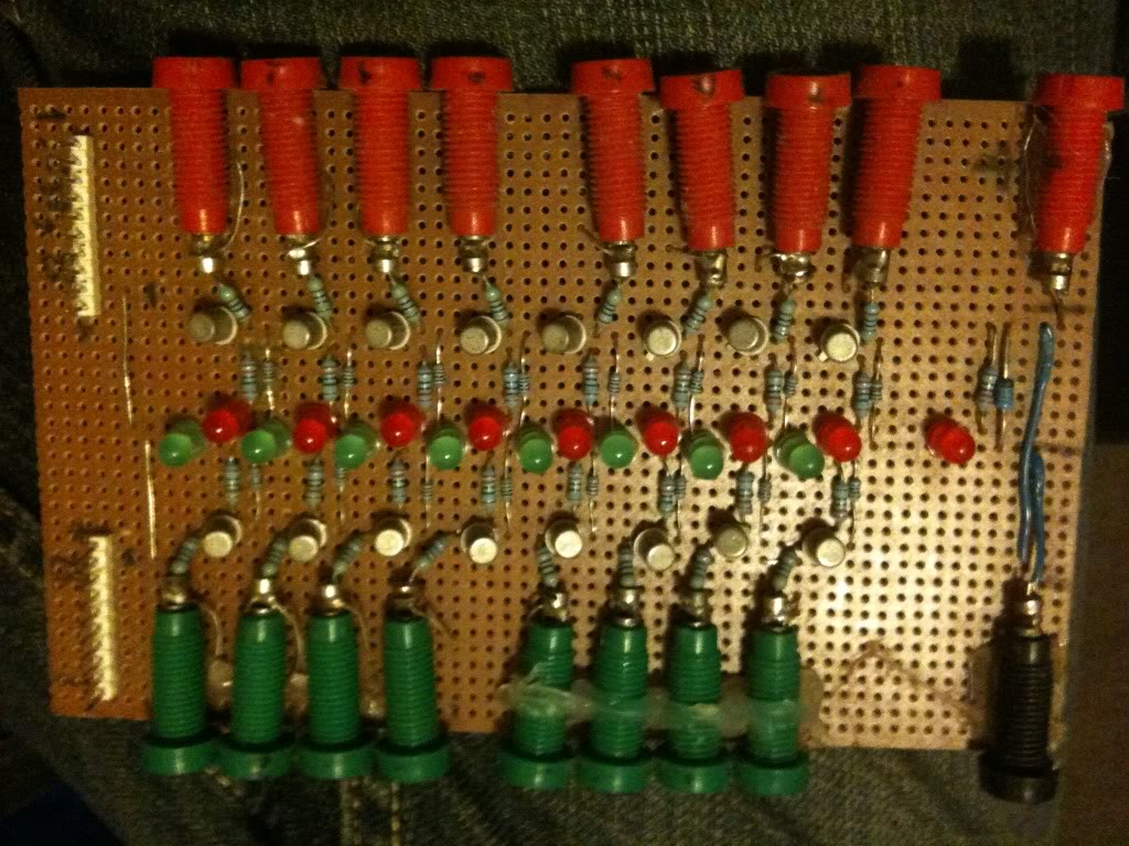
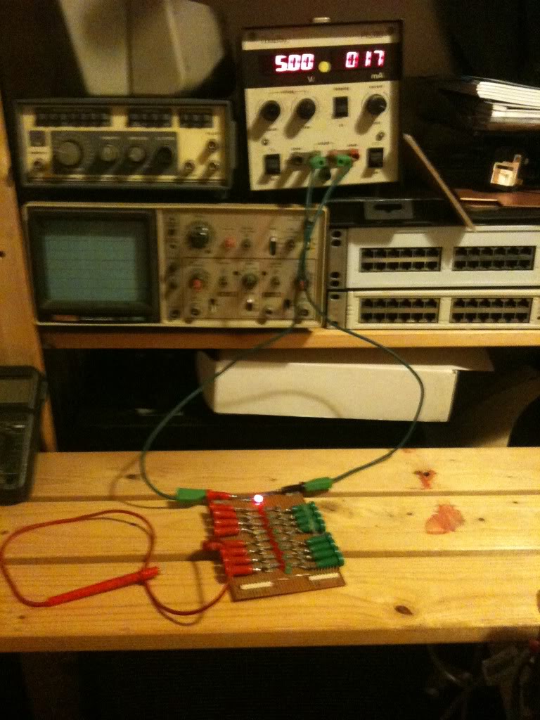
So I made my own logic output board,
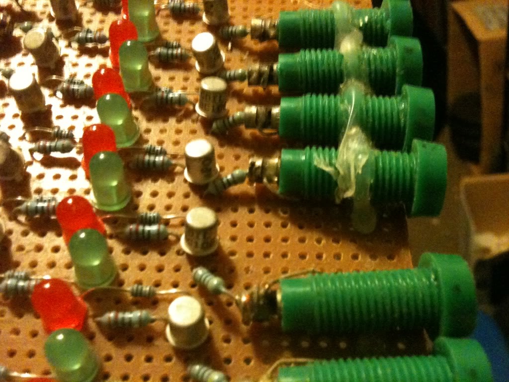
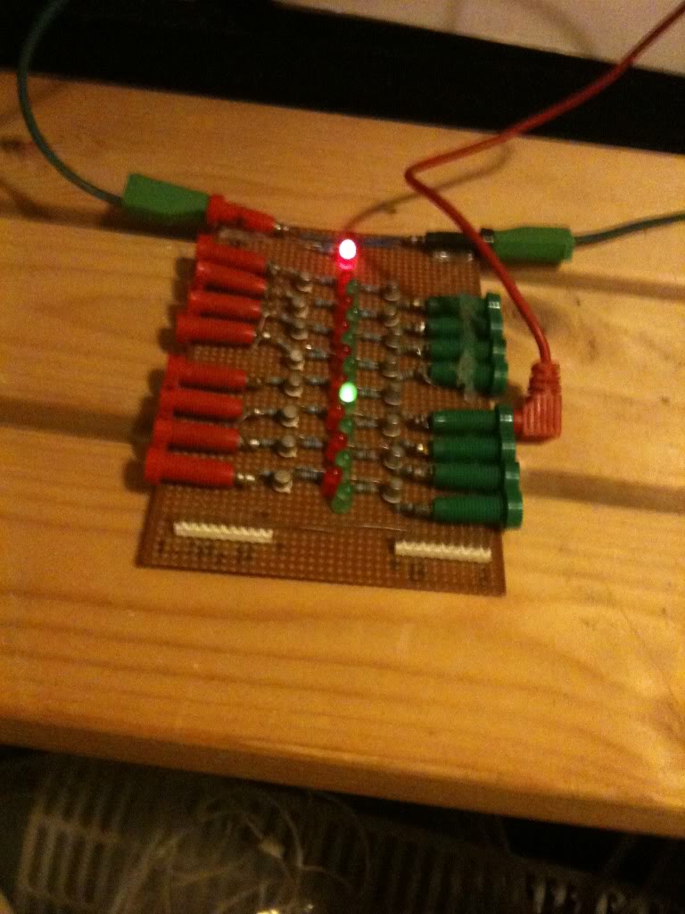
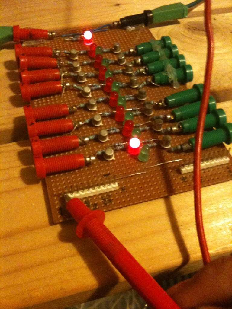
The board consists of 16 inputs, and 16 LEDs, to help identify there, these are coded red and green.

The board is powered by a five volt supply, and has an LED to signify that voltage is present, and a Zener diode to help make sure that the supply voltage does not exceed 5V.

In general you cannot rely on a digital output to have enough current to power an LED.

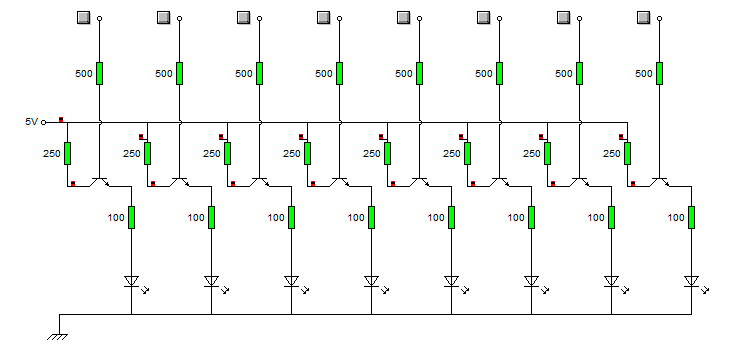
So I'm using a chip output to turn on a transistor, that transistor is then arranged as an emitter follower, that amplifies the current output from the chip, and provides enough current to light the LED.

How and why this circuit works is covered in the entry immediately prior to this.


The circuit is that simple circuit, and it's repeated 16 times


At the bottom of the board there are two ten pin connector, these are 8 logic inputs, and a + 5V supply rail, and a 0v rail.

So I can attach my PSU to this logic indicator board (using the voltage inputs and 4mm plugs), and use the board to power my circuit, with nothing more than a simple ribbon cable carrying the supply and signals.

Here are some more pictures of the board, with a probe attached to one of the inputs, and showing a voltage applied to the pin inputs also.

The board powered up:

Logic high applied to an input:

And showing the pin inputs:

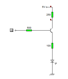
so the complete schematic is as follows, this is only one side, but just repeat on the other side.


Whether you decide to put a 5v zener diode across the supply, or an LED to indicate that the device is on, is up to you.

The actual connectors are attached to the board by a loop or wire attached, and soldered into the board, then to hold them a little more securely they are also hot glued to the board.

Thursday, August 11, 2011

Electronics Lessons: The Transistor Simple Circuits (Lab 2)

So in the last lesson I talked about the transistor, I talked about how you could turn the transistor on to a fully conducting state.

I also mentioned that transistors could be used as current amplifiers.

You'll use a current amplifier when you need a little more power to switch on an output than that output can supply.

We discussed before how the transistor was off, and how it could be turned on.

So, lets make a device that puts a light on with the presence of a voltage, even if that voltage source doesn't have the power (current sourcing capability) to light up the light itself.

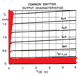
In this tutorial we're interested in two areas of the transistors output, because we're going to use the transistor as a switch we'll either have the transistor in the cut-off region (off), or the saturation region (on) of it's output characteristics. (There are the areas marked in red in the chart below).


The Circuit
What we do is connect the input to the base of the transistor, we use a resistor to ensure that not too much current is pulled from the voltage source that we're detecting.

We'll also put a resistor between the circuit voltage source, and the transistor to limit the current being drawn from the source.

Our light will be an LED, we're expecting that the voltage going to the LED will be 5V at most, but as little as 3v so we look at some data sheets for LEDs and we find that the there are a couple that we can't use, (some have Vmax as 4v), and others will tolerate a higher voltage, but won't light with only 3v.

Eventually we come across the L-53GD-5V made by Kingbright

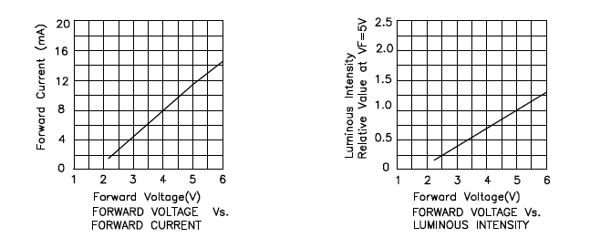
It has the following characteristics.


So we can see that it'll be on, and bright at 5v, and it will turn on, (though only be half as bright) at 3volts, (we're interested in sensing 5v Logic levels and 3.3v Logic levels right?)

Elsewhere in the data sheet it tells us that the maximum current is 17mA
We know that our greatest voltage going through the LED will be 5v
So we use ohms law to determine the resistor needed.

5/0.017 = 294

So we really want to make the total resistance between the supply voltage and the indicator LED around 300Ohms
In case you're interested

3.3/300 = 0.011 or 11mA available for the 3.3v logic level to light the LED.

I say the 3.3v, remember this is a current amplifier, not a voltage amplifier. The voltage is going to remain the same as what's going into the transistor base.
Anyway, at 3.3v the LED only draws some 6mA, so there is plenty of current available. (and that 11mA is below the devices max draw of 17mA

Schematic
Here is the schematic of the circuit.


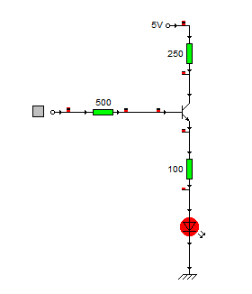
And here's what happens when a logic level of 1 (+5v) is applied to the base resistor


When the circuit is on it pulls around 6ma from the logic source, and the current going through the LED is about 14mA.

Stay tuned to see this idea scaled up!

Monday, July 25, 2011

The Workbench/shop stock lists. Woodworking (Beginners list)

Just as with the Beginers Electronics Bench I'm writing a list of essential tools for a beginner woodworker.

Just the same as electronics, this is the list of stuff that you'll need to get you started. I'm assuming that you're looking to build small things, by small things I mean enclosures for your projects, hifi speakers, pictures frames or small boxes etc. This list of tools will enable you to build a huge project like a tree house, or a wooden bike, but before you embark on any project like that you need to not only have the basic tools, but also the ability and practice to use them. (there's that word practice again, yes, working with anything and creating anything is a skill, to develop skills you have to work at them. that's the difference between first year/grade and final year projects, you've spent years practising by the time you get to your final year so you've got more knowledge and more skills.)

Anyway, this list should get you started.

A clamp
There are many different kinds of clamps, G clamps, C clamps, sash clamps. clamping devices come in all different shapes and sizes.

The reason that I put a clamp at the top of the list is because I believe that this is the most important thing that you want.
Your project might only be gluing two bits of wood together, unless you want to sit all night holding the bits together by hand, a clamp is essential.

You can also use a clamp to hold a piece of material to a surface as you cut material off of it.
(it's much easier to cut through something when it's held steady!)

You can get an idea of the variety and kinds of clamps available by looking here;
http://search.diy.com/search#w=clamp

As a starter set I'd say that you couldn't go wrong with buying a cheap set of three C clamps. they come in different sizes enabling you to work on a variety of projects sizes.

Cost £5 (total cost £5)

A Saw
You've got a way to put things together, now how about a way to take things apart?

Saws come in all variety of shapes and sizes, and are used for different things.
your average hand saw costs less than £10 and has a blade that can do cross cut (cutting through the grain of the wood), or rip cuts (cutting along the grain of the wood.)

If you plan on making only big things, then a large 9ppi saw is probably all you need that'll rip through wood quite fast, if you're planning on making much finer stuff (furniture for example) you might want a saw with finer teeth, perhaps 14ppi.

What's PPI? PPI means points per inch, it's the amount of teeth on a saw inside of one inch measured along the blade. it's as easy as that.

Saw teeth rip through things by wearing them away, the more saw teeth that there are in a given inch, the finer the teeth will be, and the cleaner the cut that they make will be, though the longer it'll take to get through the material you're cutting, as it'll rip away less material on each pass.

the picture on top represents a 7ppi blade, the one on the bottom a 14ppi blade, the 14ppi blade is clearly much finer.

As a starter, I'd recommend that you get an all purpose hand saw like this
http://www.diy.com/diy/jsp/bq/nav.jsp?action=detail&fh_secondid=9676731&fh_location=//catalog01/en_GB/categories%3C{9372015}/categories%3C{9372043}/categories%3C{9372176}/categories%3C{9392049}/specificationsProductType=hardpoint_saws

Cost £3.50 (total cost £8.50)

There are of course different saws for different jobs, a fret saw is used for cutting shapes as the blade is very thin and can turn corners.
A coping saw has a round blade and can cut up, down and side to side.
A tenon saw has a metal bar that re-enforces the top of the blade to make sure that it doesn't move of flex. As with most tools, different saws are suited to different jobs. I don't recommend buying them all at once, but certainly if you have a specific job that requires a specific tool then you should buy that tool.

Tape measure
Ok, so you can hold your work piece still now (clamped to the kitchen table), and you can cut through it, but how will you need to know where to cut?

Get a tape measure.
Cheap tape measures might lack a cool feature like being able to lock the tape out, but they work just as well at measuring stuff. So just grab a cheap one.

Cost £5 (total cost £13.50)

Square
So now you know where to cut, you'll want to draw a line on the wood that you're cutting, of course you want to make sure that your line is perpendicular to the edge, not going off at an angle, so you'll want to use a square.

http://www.diy.com/diy/jsp/bq/nav.jsp?action=detail&fh_secondid=11247668&fh_location=//catalog01/en_GB/categories%3C{9372015}/categories%3C{9372043}/categories%3C{9372176}/categories%3C{9392047}/specificationsProductType=measures/specificationsSpecificProductType=squares

That set I've linked to has a L shaped piece of metal that you can put on top of a piece of work (where you can't get to the edge) and line up the work with the square, and a thing that is like a ruler, with an adjustable piece of metal on it, the adjustable piece of metal slides in and out allowing you to set it a distance from the end, it also has 90 degree and 45 degree edges.

Cost £10 (total cost £23.50)

Marking
I have of course assumed that you already have a pencil, or a pen to mark your surface with.
this is your choice, you can buy those big square carpenters pencils (and get to feel really manly as you sharpen them with a knife!). You you can go to a pound shop and buy a pack of regular pencils, and a pack of chunky markers, and a pack of fine markers. (for a pound per pack.)

Cost £3 (total cost £26.50).

Hammer
Used the world over for making noise.

There are many many different types of hammer. I've got more than 1 hammer, (cross pein, ball pein, claw, club, rubber).

I'd recommend that you get a few different types of hammer too.
I'd really recommend a 12oz ball pein hammer (the one that looks like it has half a ball on the opposite side to the flat side.)
a 4oz cross pein hammer, sometimes called a pin hammer (the really light weigh one that has a flat chisel like looking part opposite the hammer surface.)
and a 16oz Claw hammer, (the one with a curved surface opposite the hammer face for pulling out nails.)
These hammers will cost £5 - £10 each they all have different uses.
The smallest cross pein hammer is used for fine work, like hammering in veneer pins into some work.
The ball pein is actually more of a metal work type hammer, but I tend to find that I use this the most as the weight of it feels right to me.
The claw hammer is the heaviest and can be used for much heavier work, (driving in big nails). Personally I find that, even though there is only a 4oz difference between the ball pein and the claw hammer, that added weight makes the hammer more unwieldy, and less suitable for fine work. If the hammer is unwieldy then it's harder to control, and you;re more likely to hit your fingers.

Cost £30 (total cost £56.50)

Punch
No, not the drink, the tool, it's basically just a metal rod that you use for pushing nails below the surface, or driving nails to the surface in places where you don't want the hammer face to have any chance in coming into contact with or marking the work that you're doing.
You can just use a really big nail, but since a set of five of these (in different sizes) is only £6 (on DIY.com,) you may as well get the right tool for the job.

Chisel
This is one of those things where you'll really get what you pay for, but also one of those things where good tools cost good money.

For a start I'd recommend (from diy.com) the B&Q value set of three chisels, there are three different sizes, and they are sharp when you buy them at least.
Basically these are good enough. Chisels do get blunt, so you may want to consider a sharpening stone too.

When I first started out I bought the B&Q value set, and used these until they were pretty blunt, you'll know when they get blunt because they become difficult to work with, they don't cut well, require more force, slip more (read between the lines here, blunt tools are difficult to work with, and will slip around on your work piece, i.e blunt tools are more dangerous than sharp tools.) Anyway, later on, when the chisels needed sharpening, I bought a different (better) set, that came with a sharpening stone, That set was more expensive.
I sharpened my value chisels, (which was good), and now I have a set of cheap chisels that I'll happily use for rough work, or work that might hit a nail or something, and a set of nice chisels that I'll use then I know that the wood I'm dealing with it good.

Cost £7 (total cost £63.50)

Drill
I covered drill in my how and where to buy tools and materials post before, the drill you want will really depend on the work that you want to do.
If you're only ever drilling softwood in a garden shed with no power, then a battery drill is ideal.
If you want to drill into hardwood for long times, then you really want a mains powered drill. If you plan on drilling into walls, you really want a hammer drill.
The type you need depends on what you need to do. and the brand you get also depends on what you need to do.
As I've said before, professionals buy DeWalt drills because they are dependable, that tool will likely outlive the person who buys it. They cost a lot, but to a professional they don't cost as much as numerous trips to the hardware store to buy a new drill (because time spent in the store is not time spent on the job.)
If you can afford professional tools, (like DeWalt, or Makita) then by all means go buy those tools. If you find them on sale then you might want to buy them (but even at half price they are often four to five times more expensive than the drill that I normally use).

For most, all you need is a choice between normal drilling and hammer action, and variable speed (so if you only pull the trigger a little it goes slowly, pull it all the way in then it goes fast).

I bought my drill from Aldi, for about £15, but to be fair, they aren't sold there all the time.
so I'll say:

Cost £30 (total cost £93.50).

Drill bits
Once you've bought a drill you'll want a set of drill bits.
there is a difference between wood, metal and brick drill bits, but you should be able to find a set with an assortment of sizes (3mm = 10mm) and functions for around £20

http://www.diy.com/diy/jsp/bq/nav.jsp?action=detail&fh_secondid=11407674&fh_location=//catalog01/en_GB/categories%3C{9372015}/categories%3C{9372047}/categories%3C{9372200}/categories%3C{9392077}/specificationsProductType=accessory_sets/specificationsSpecificProductType=mixed_sets
that's a link for some wood, brick and metal bits for £10.

http://www.diy.com/diy/jsp/bq/nav.jsp?action=detail&fh_secondid=11537590&fh_location=//catalog01/en_GB/categories%3C{9372015}/categories%3C{9372047}/categories%3C{9372200}/categories%3C{9392077}/specificationsProductType=multi_purpose_drill_bits
that's a much bigger set for £35, and includes hole saws that let you cut out big holes in wood, you'll never find a 2" drill bit., but a 2" hole saw lets you cut a 2" hole which is useful of you're making a set of PC speakers or similar.

Cost £20 (total cost 113.50)

Screw Drivers
For electronics, you probably want a specialist miniature tool kit, (the screws on an iphone for example are PH00 whilst most mini screwdriver sets only go down to PH0.)
For wood working you'll want just a normal set of screw drivers, probably in the range on 3mm flat blade to 10mm flat blades, and the same with Philips head screw drivers too.

I'd recommend either buying a set of screw drivers, I got a set of 30 brand new from a carboot sale for £5 in a range of sizes and blade types (Flat, Philips, Torx), or you could go with a screw driver with changeable bits (so the same screw driver body is used).
You can get ratchet screw drivers (these can save a lot of wrist ache having to take the screw driver out of the screw head, line it up, insert the driver into the screw head turn and repeat.)

A ratchet screw driver with changeable heads costs around £12
http://www.diy.com/diy/jsp/bq/nav.jsp?action=detail&fh_secondid=9285164&fh_location=//catalog01/en_GB/categories%3C{9372015}/categories%3C{9372043}/categories%3C{9372176}/categories%3C{9392042}/specificationsProductType=sets

Cost £12 (total cost £125.50).

That's pretty much a basic tool kit right there, it'll let you tackle a variety of tasks from the big to the small, and can all be kept in a reasonably small tool box in a corner, or under the stairs.

I'd hoped to keep the costs as low as possible, and certainly buying tools second hand for yard sales or car boot sales can save a fortune. I do not recommend buying second hand chisels, or saws, or drill bits. They will already be blunt. and as I said earlier blunt tools are more dangerous than sharp tools, they also make a mess of your work.

On the subject of dangerous.
You can't do wrong with buying a set of "rigger" gloves (thick material gloves) to protect your hands, (from both your tools and splinters).
There are no loud tools listed here, but if you are using loud tools ear defenders are dirt cheap and you should use them, if you'll be creating dust, or working in a dusty environment a dust mask is a great idea, if you've got long hair then buy a hair band.

When using a chisel, you should only push the chisel away from you, never towards your body or towards your legs. Never balance work on your lap whilst trying to put screws into it (a screw driver to the groin is going to hurt!)
When planing wood (a plane wasn't listed) always plane away from yourself, Basically, the sharp end of the tool should always travel away from your body! the only exception to this is when using a spokeshave or draw knife, these are meant to be drawn towards you. (carefully!)

Probably the most important thing I can say is take your time.
If you rush things then you either ruin your work or ruin yourself, when I was younger, I thought I could cut through a piece of metal faster by just moving the saw faster, all that really happened is I ended up slipping and performing my own surgery on myself with a hack saw, exposing your bones isn't fun.
Friday, July 22, 2011

Electronics Lessons: The Resistor Simple Circuits

Ok, so it's time to crack out the components and do some simple experiments.

Lessons are boring, I don't need to tell you that though. If you've read through the resistors lesson you may have switched off half way through, you may have just clicked away.

Endless theory is boring. So... lets crack out a few components and start making something nice and simple to illustrate some of this theory.

Equipment
For this lesson, you'll need
>a 9v battery
>a battery clip to attach wires to the battery.
>a small light bulb (and possibly bulb holder).
>and about 3 100ohm resistors, (brown black black).

If you have one then a multimeter that measures voltage would be good.

You should be able to nip into your local radio shack/Maplin/electronics hobby store and get all of these things for less than £5.

Method
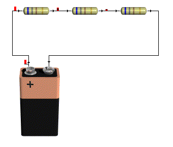
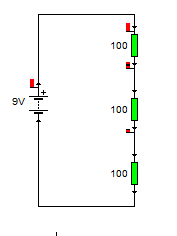
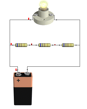
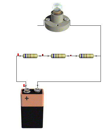
The first thing that you want to do is join the three resistors in series, and attach them to the battery, whether you practice your soldering skills, use a breadboard (as in the little plastic thing), just twist the legs together to form a connection or even use a breadboard with screws and screw cups to hold the components, if doesn't matter, all you need to do is connect the resistors in series and attached then to the battery.

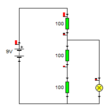
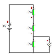
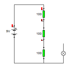
I'm going to illustrate this with a series of pictures, that should show you what you're looking at, and the schematic diagrams that represent what the circuit is.


Next attach one side of your light bulb also to the negative side of the battery.


Now you want to attach the other side of your light bulb to the positive side of the battery.
you should see if lights up very bright.


Now remove the connection from the light bulb to the positive side of the battery, and connect the battery to the second leg of the first resistor, you should see that the bulb still lights, just not as bright.


Now remove that connection and connect it to the second leg of the second resistor. the bulb should light a little bit, but it won't be very bright at all.

Extra Activities
If you don't have a multimeter then you should just skip over this bit to the results section.
Now take the light bulb out completely, switch your multimeter onto measure volts in the 20volts range, (or as close to 9volts without being under 9volts depending on your meter).
Touch the (usually black) Comm probe to the negative terminal on the battery and the other (usually Red) lead onto the positive terminal of the battery.

The display should read 9Volts,

Now touch the red lead onto the second leg of the first resistor, it should now read 6Volts.

And if you touch the second leg of the second resistor it should now read 3Volts.


Results
What you have created is a potential divider.
In an earlier lesson we talked about electricity as being a potential energy, (though not in the strict physics sense) this little collection of resistors is dividing up that potential so it reduced as you go down the ladder.

We talked about how power and voltage were linked earlier, the reason that the bulb shines less brightly when a lower voltage is applied to it is because there is less power going to the bulb to make it shine.

There is an equation to work out what the voltage at the given points of a potential divider will be.

That equation is

Vout = (Z2/(Z1+Z2)) x Vin

This formula is using Z in place of R, it may be a little confusing at first, but go with it!

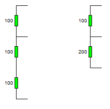
I've made it a little more complicated using three resistors in the example, but that's ok, we learned earlier about how to deal with resistors in series, you just add them together.

Lets look the voltage on the second leg of resistor 1

We know that the input voltage Vin is 9v
The resistor R1 is 100Ohm, so Z1 = 100Ohm
but what's Z2, (yes if you look at the schematic R2 is 100Ohm, and R3 is also 100Ohm).

For this equation, since we're measuring at the second leg of R1, Z2 is the total resistance of R2 and R3 which are in series, (so we just add them together.)


So lets fill in that equation now.

Vout = (Z2/(Z1 + Z2)) x Vin

Vout = (200/(100 + 200)) x 9
Vout = (200/300) x 9
Vout = 0.666666666 x 9
Vout = 6

That's what we measured!

Now let's look at the voltage at the second leg of resistor 2,

This time Z1 is the top two resistors (R1 + R2) and it's 200Ohm
The voltage is still 9v
and Z2 is R3, which is 100Ohm

Vout = (Z2/(Z1 + Z2)) x Vin
Vout = (100/(200 + 100)) x9
Vout = (100/300)x9
Vout = 0.333333333 x9
Vout = 3v

Which again is what we measured! so everything is looking good.

Monday, July 18, 2011

Converted ATX Power supply

Recently you could be forgiven for thinking that this had changed from the idiots guide to puttin' shit together, to the opinionated guide to how you should have done your projects, or the idiots musings and bad teachings.

I'm definitely going to continue the tutorials because it's actually quite fun to write them, and I'm finding that as I go over the ground again, I'm re-remembering some stuff that I'd completely forgotten about. But this post is right back to the core of why I even started this blog, and that's to share something that I've made.

Firstly,


There's your warning, but if you can't figure out for yourself that there is an element in danger in modifying anything that plugs directly into the wall then you should probably stop reading now and go elsewhere.

Theory
The theory for this is so simple, I have a power supply (a computer power supply), and I want to turn it into a bench power supply, so I pretty much just need to cut off the wires that aren't needed, and attach the appropriate plugs to the wires that are need!

How it works
The computer power supply maker has done all the hard design parts for me it's a switch mode power supply, mains supply and as it's switching faster, the transmission of the energy inside the ferrite core, basically that means that inside the power supply is switching on and off at a very high frequency, this is much faster than your 50Hz s of the transformers inside is more efficient, more efficient means that you're not generating as much heat, and not as much energy is wasted as heat.
A traditional power supply, would require an absolutely huge iron core surrounded by pounds of wire to be able to get the same kind of output power that a switch mode power supply (SMPS) gets.

Why it's important
The high frequency is important as that's what allows the supply to be so efficient. The fact that someone else made it is important because it means that you can make this supply inside a single afternoon.

If I was designing my own SMPS, I'd probably need to research for at least days, if not weeks, I'd need to source components. Create circuits to sense the output voltage and adjust the input if necessary, it'd be a lot of work, yet I can turn an old supply from a broken PC into a perfectly reasonable bench supply in a matter of hours.

Simple experiment
Before even breaking out the screw drivers, or plug in the soldering iron. I took a look at the computer power supply unit.

There is a big plug with either 20, or 24 pins on it. inside all these pins there will be a single green wire, with a black wire either side of it.

Using a small bit of wire I pushed it into the pin connected to the green pin, and one of the black pins from either side. The fans spun into life, and voltage could be measured at other pins.

You can just use the supply like this with no further modification, inserting your bit of wire to turn it on, removing your bit of wire to turn it off.

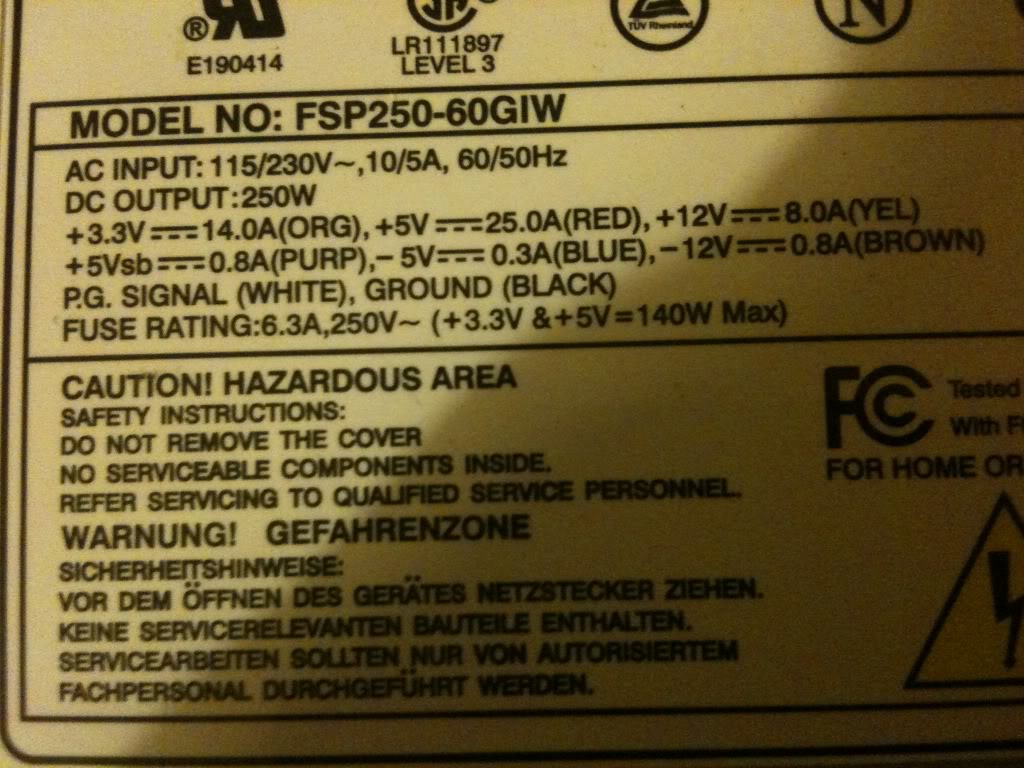
On the side of the case there was a table that telling me what colour wire carries what voltage, and what the limits of the current capabilities are for each voltage. this made it a whole load easier that searching for a pin out on-line for the ATX plug to know what pin was what.


Converting a power supply

Parts and tools required
>an old computer power supply
>a screw driver
>some terminal posts
>Wire cutters
>A switch (push to make locking switch)
>A LED
>A 10mm drill bit
>A drill
>A 6mmDrill bit
>Insulated screw terminals -these are not important, you may chose to leave these out
>A 470Ohm resistor
>A soldering Iron
>Solder (flux core)

Taking it all apart

The first thing that I did was take off the lid of the box, The fan is connected directly to the board with no plug to remove it, so I removed the fan from the case lid.
Modifying the part
Lets deal with the lid first,
I knew that in the lid i'd need to put a switch (basically in place of the wire that I had before),
You might want (I did) a nice LED to tell you that the supply is on.
I also wanted to put plugs that to connect the wires to in the lid.

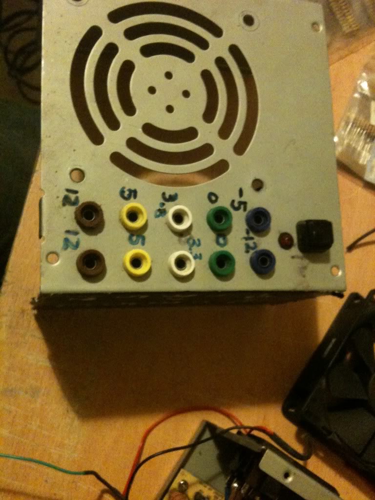
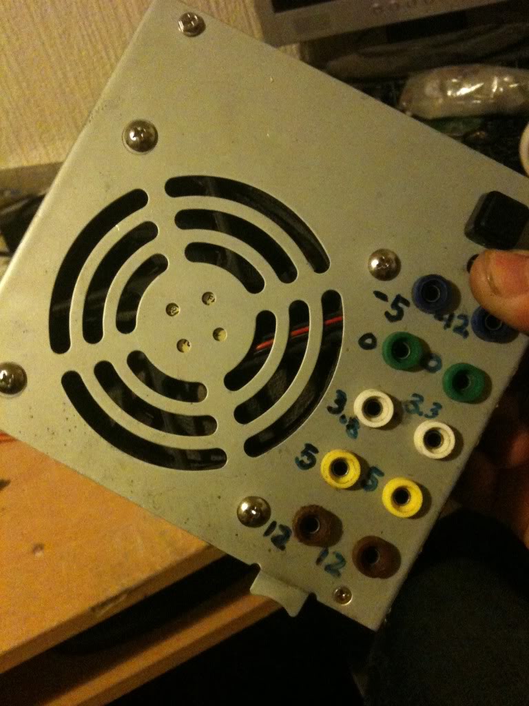
I chose to mount my plugs in two columns, (2 x 12v, 2x 5v, 2x3.3v and 2x0v) as these are the voltages that I'll use the most often, then I have one plug for -5 and -12, as I'll use these less often.
As it happens, banana plugs are usually stackable, so you won't really loose an functionality just using a single row of connectors.

When I looked on the inside, of the power supply, I saw that there were basically two sides, one side has big heat sinks in it, and the mains plugs next to it, the other side is fairly low profile leaving the top of the case empty. I decided that I'd like to keep my plugs away from the side with exposed mains connectors that the bottom of the terminals might hit, and away from the heat sinks for the same reason

I marked out the lid and drill the holes for all the part to go into.
Then installed the plugs, LED and switch (I used a simple black collar for the LED it's called a panel mount and costs about a penny. -you could leave the LED out completely).


I just used a marker pen to write the voltages on the top of my supply, you might use nothing relying on the colour of the plugs to tell you the supply voltage, perhaps you might like to try etching or engraving, or using a label printer, I don't really care, pen works for me, and that's good enough.

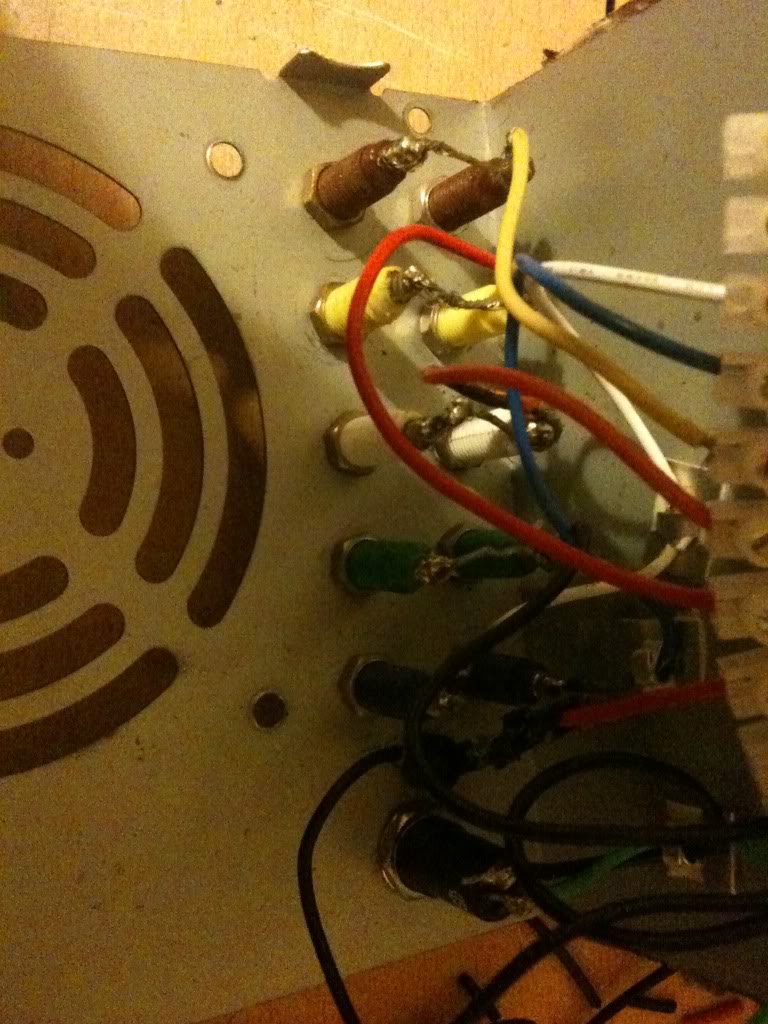
Next as I have two plugs for one voltage, I connected these plugs, using a piece of wire running between them.

I also want to add a 470Ohm resistor to one leg of the LED (this is to limit the current that goes into the resistor).

(That'll connect to the 5v rail 5/470 = 0.01A or 10mA, enough to make the LED glow, you might like a bigger or smaller resistor depending on the needs of your LED, it's also 1/20th of a watt, so a simple small 1/8th watt resistor will be fine.)

I soldered leads to everything ready to connect to the terminal block connector.


Finally I was able to stop working on the lid and move onto modifying the actual PSU.

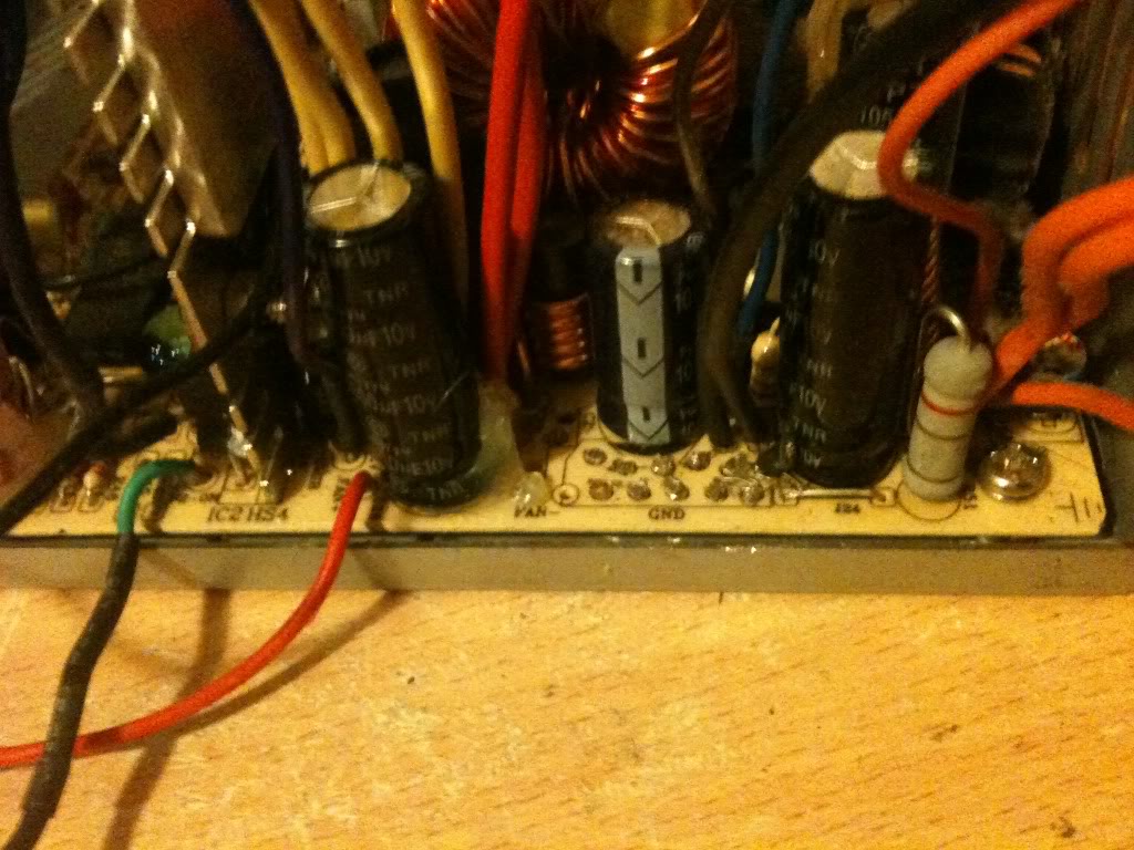
One thing that you'll notice is that the wires are colour coded depending on their job. And there are a LOT of wires that are the same colour, in the supply I used there were about 10 black wires, all 0v, all from the same pad on the PCB!
I needed 3 black wires, could have got away with 1, but three was good (one for the power button, 1 for the LED and 1 for the output plug).
I really only needed 1 -12 wire, only 1 -5 wire, only 1 +12 wire. and two +5v wires (one for the plug, and one for the LED.

You do only need 1 3.3v wires, but in addition to the thicker wires you must keep the very thin orange wire, this is the sense wire that determines what voltage is being generated, and regulates the supply, without this wire your supply can float.

Anyway, I cut away the wires that I didn't need (that I could get to)


I couldn't get to cut the red or yellow wires, so I'm going to tie these off later in some spare terminals on the connector.

Putting is all together
So I'm now in a position where I've thinned out all the wires that I don't need, and I've trimmed all the wires that I do need to about four or five inches long so that I have plenty to work with.

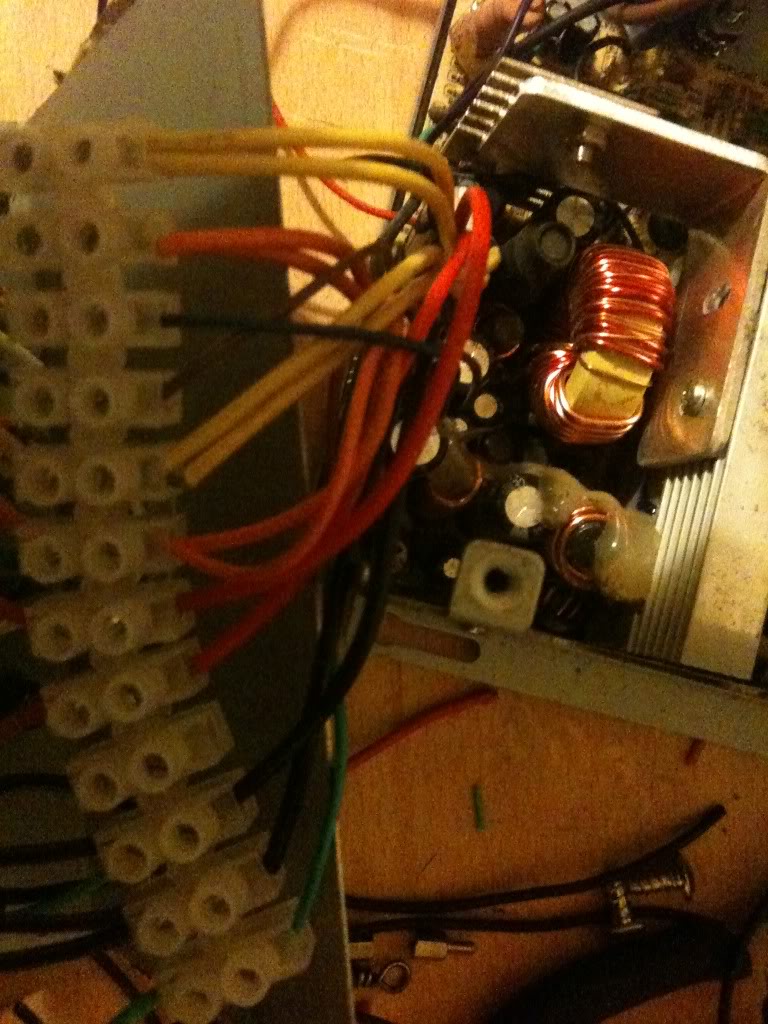
Now I striped back the wires, and attached them to the terminal block.

It doesn't matter what order you make the connections in, just that black wires connect to ground, terminals, and the negative side of your LED, also that there is a black wire attached to one terminal of your switch.

You want the green wire to attach to the other leg of your switch, and a red wire to attach to the LED for your "on indicator".
Yellow wires are alwyas 12v, Orange is always 3.3v, Red is always 5v, minus five and minus 12 however do not appear to have a set colour scheme, and as such may vary.

The colours were written on the outside of the supply I used, you may have to poke around with a multimeter. or look for an ATX pinout and just select the correct wire from the plug.


Once all the wires were connected I attached the fan to the top of the case again, and put the top of the case onto the bottom. as I said earlier, make sure that the bottom of your sockets do not touch the metal bits inside. Also make sure that no wires are touching the heat sink where the insulation could melt, and that no wires or the large terminal block is getting in the way of the fan.


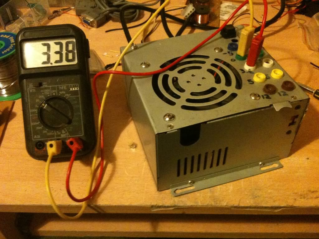
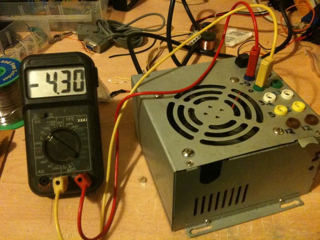
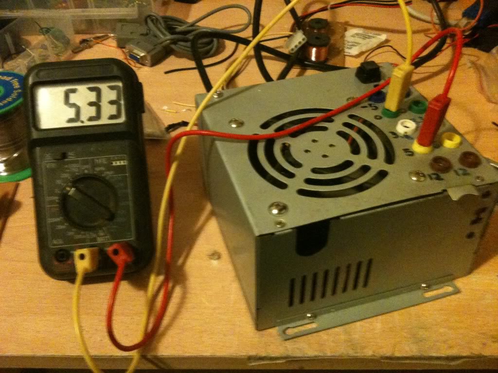
Now I measured The output voltages using a multimeter.


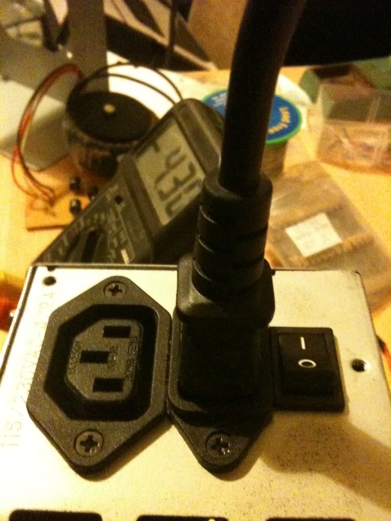
Since I'm always seeming to run out of power outlets, I chose a power supply that lets me get mains power out as well so I can daisy chain equipment together.


Costs
This is not the cheapest project in the world, but it is cheaper than buying a power supply with the same amount of usable outputs, regardless of whether those outputs are of a fixed voltage, or five variable voltages. I had everything either in my parts box/junk bin so this really cost me nothing.

There are 10 4mm sockets, these are 20 pence each from Rapid Electronics
http://www.rapidonline.com/Cables-Connectors/Connectors-Single-Pole/4mm-Connectors/4mm-Sockets/63893
(total cost £2)
The Square Single pole single throw switch cost 36 pence.
http://www.rapidonline.com/Electronic-Components/Switches/Push-Button-Switches/Square-push-switches-1A/30275
(toal cost £2.36)
LEDs cost around 9 pence (or less) (when you buy them in bulk).
here's one for 6 pence http://www.rapidonline.com/Electronic-Components/Optoelectronics/5mm-LEDs/Low-current-5mm-LEDs/29336
(total cost £2.45)
Resistors cost even less than this when bought in quantity.
http://www.rapidonline.com/Electronic-Components/Resistors-Potentiometer/Carbon-Film-Resistors/CR12-0.125W-Carbon-film-resistors/65192

65 pence for 100, seriesly people stop shopping at Maplin/Radioshack

Rapid cost 65 pence for 100, (or ~ half a penny per resistor).
Maplin cost 25pence per single resistor. (50 times more expensive).
http://www.maplin.co.uk/components/resistors/metal-film
If your project requires 3 resistors, it's cheaper to order on-line and have 97 spare/left over!

(total cost £3.10)

Now comes the expensive part, if you don't have a spare power supply laying about, (and don't have the resourcefulness to find one for free), then you'll have to buy one. for the princely sum of £7.86!
http://www.ebuyer.com/product/20083

Total cost £10.96! Much cheaper than any other power supply that I know of. in fact we're really knocking on the cost of a single voltage wallwart cost here, which has a lower power capacity and only 1 voltage output (which may or may not be adjustable!)

Alternatives, -and Why I didn't use them
This is something I started when I wrote up the red light torch, there are so many ways to crack an egg. So my way is not the only way, just the way that I chose on that day.

Spring terminals:
Spring terminals are useful if you're doing a lot of breadboard work, without a breadboard that has power terminals, but practically everything I've got is set-up for 4mm banana plugs, my multimeter, the power terminals on my breadboards, crocodile clips connect to 4mm plugs. Spring terminals may well have been cheaper, and indeed wouldn't require me to buy 4mm plugs to go with them, but since I'm set-up for using 4mm plugs it makes sense to use them

Binding posts:
Yes, these are just like 4mm sockets, except that you can also attach bare wires and screw them down, making them a whole heap more versatile. The only reason that I didn't use these is that I didn't have any in my parts box, and I did this project one evening after the shops were closed.

Directly soldering the leads:
I could have missed out the terminal block connector, and indeed the first time I made this supply I did. without that chunky connector however there are two things.

The wires that you can't cut off at the board end up loose in the case, you can wrap them in tape, but it's a bit messier than being able to put them in a spare space on the terminal block.

The first time I built this supply I soldered straight to the plugs, I broke that supply, and it was quite a PITA to remove all the old connections to put new connections on it. if I ever need to change the actual board again I can just take the case lid as I did this time and bolt it to a new supply just cutting and stripping the few wires that I need to use.

Sandbar resistor
Instead of just a locking switch on the green "power on" line, you should use a resistor on the 5v line to apply a load to the circuit that'd sense that it's on. That's the "proper" way of doing it.
I didn't do it like this because...
1> The sandbar resistor has to be a high power resistor, tied to the case for cooling, this seemed like it's take a lot of space inside the already cramped case, and is a part that's going to increase the idle power consumption of the power supply.
2> My supply works without it, so I'm not too worried really.

External plug-set with ATX/Molex connections
In the theory section you saw that it's possible to turn the supply on with nothing more than a piece of wire, I could have kept the supply as is, put molex connections on my projects, of I could have just made a board with my 4mm sockets arranged just as they are where the power supply just plugged straight into it.

The good side of this is that I wouldn't have had to open the case at all. So if you have a skittish partner or parents then you may wish to go this route. (If they aren't happy for you to plug things in after you're taken them apart and soldered bits to them!)

On the other hand, I think that you'll end up with something a lot messier.