Monday, September 17, 2012

Electronics Lessons: Making Gates from Gates

The most useful logic component that you'll ever find. -the NAND Gate.

So I've looked at logic gates and said that there are three Basic ones, AND, OR, NOT, that there is also an exclusive OR XOR, and that on top of that there is XNOR and NAND that can be made by adding a not gate to the end of the outputs.

We've had a peek at boolean algebra to show how things can be proven algebraically, and looked at truth tables to give a much more show and tell approach to showing binary states and logical outputs.

So now we'll look at how you can make any logic gate from a NAND gate.

We'll start by looking at the truth table for the NAND Gate

A B | Q
======
0 0 | 1
0 1 | 1
1 0 | 1
1 1 | 0

NOT
So lets start with the simplest functions.

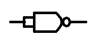
Imagine that we connect both inputs together, so that inputs A and B are both the same,
now we're only concerned with states 0 and 3 on the truth table.

A B | Q
======
0 0 | 1
1 1 | 0

And it's only really a single input,

A | Q
====
0 | 1
1 | 0

Connecting both inputs of the NAND gate has made the NAND gate into a NOT gate.
AND
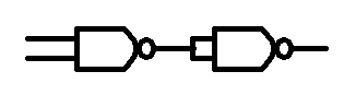
So how do we make a NAND gate an AND gate

A . B = //(A . B)
A . B = NOT NOT A AND B

yep, we just have the output of a two input NAND gate, connected to both inputs of a second two input NAND gate.
OR

Lets start with a truth table

A B | A + B | /A /B | /(/A . /B)
=======================
0 0 |    0    |  1  1  |    0
0 1 |    1    |  1  0  |    1
1 0 |    1    |  0  1  |    1
1 1 |    1    |  0  0  |    1

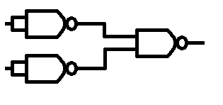
So first we make a couple of not gates, just like above, then we feed those to a NAND gate.
XOR
So we have our basic NOT, OR, AND gates all figured out, there is also the NAND gate already given (as that's out basic construction block)

Now we're going to look at XOR

To understand what XOR is I'll put the term into English.

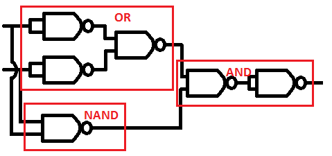
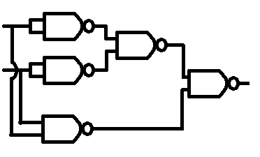
XOR is, A or B, but not A and B

(A + B) . /(A . B)
Let's draw up the truth table for that one.


A B | XOR | OR | NAND | OR AND NAND
================================
0 0 |    0    |  0  |     1    |          0
0 1 |    1    |  1  |     1    |          1
1 0 |    1    |  1  |     1    |          1
1 1 |    0    |  1  |     0    |          0

XNOR

We can create an XNOR gate by adding a not gate to the end of our XOR gate, but Given that the last element is already a NOT gate, (NAND with conjoined inputs) rather than having two not gates back to back we can just remove the not gate already there.

NOR
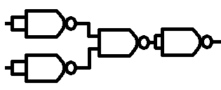
And of course the NOR gate is just the OR gate with a NOT gate added to the end.

Monday, September 10, 2012

Electronics Lessons: Truth Tables

In the blog post that covered what logic functions there were I drew small tables that listed the input and showed what the output of a system would be.

In the Boolean algebra blog post I proved a weird looking rule with the using a couple of the little tables.

Those tables are called truth tables.

They depict what outputs occur as the conditions of an input.
You can use truth tables to prove logical statements.

Proving DeMorgan Theorem
As ever writing is nothing without context

So as an exercise in truth tables I'm going to look at the two rules of DeMorgan theorem.

These two rules are
/(A + B) = /A . /B
and
/(A. B) = /A + /B

This is easier to do on paper than it is on a computer screen writing in text, but here goes...

First we need to look at how many inputs we have,
We have A and B, so we need two columns.

Our first conditions are

NOT ( A OR B )

So to start with we'll draw the truth table for
A OR B

A B | Q1
=======
0 0 | 0
0 1 | 1
1 0 | 1
1 1 | 1

Then we need to apply the NOT operation to the output Q1
Q1 | /Q1
0 => 1
1 => 0
1 => 0
1 => 0

So we know that the output of the truth table for /(A+B) looks like 1, 0, 0, 0 (for states 0,1,2,3)

Now we'll investigate the truth table for /A . /B

Lets start with A AND B

A B | Q
======
0 0  | 0
0 1  | 0
1 0  | 0
1 0  | 1

But what about NOT A and NOT B

/A /B | Q
1    1  | 1
1    0  | 0
0    1  | 0
0    0  | 0

So we know that the output of the truth table for /A . /B looks like 1, 0, 0, 0 (for states 0,1,2,3)

It's the same.

For a more complex problem it might be better to draw everything out inside a single truth table:

We'll do this to prove Demorgans second rule:
/(A . B) = /A + /B


A B | /A /B | A . B | /(A.B) | /A + /B
===========================
0 0  |  1 1    |    0     |    1      |    1
0 1  |  1 0    |    0     |    1      |    1
1 0  |  0 1    |    0     |    1      |    1
1 1  |  0 0    |    1     |    0      |    0


You see that the last two columns are the the statements used in DeMorgan theorem, and they do indeed prove DeMorgan theorem is correct.


States.
One thing mentioned above was that the states of inputs could be assigned names.

Where you have defined input names that are ordered, A, B, C or In1, In2, In3 you can assign the different states values in accordance with the binary numbering system

A B C = State name
0 0 0 = 0
0 0 1 = 1
0 1 0 = 2
0 1 1 = 3
1 0 0 = 4
1 0 1 = 5
1 1 0 = 6
1 1 1 = 7

Monday, September 03, 2012

Electronics Lessons: Boolean Algebra

There is nothing that would turn a person off a subject more than the mention of algebra.

But, do bear with me.

As with ordinary algebra we'er using letter to represent something, but in this case we're using it to represent states on inputs compared to what ew want our output to be.

I introduced notation in the last post that describes how to write logical expressions.

So lets just straight in.

In real maths we know that 1 + 2 = 2 + 1, both are equal to three.
The same is true in boolean algebra,

1 + 0 = 0 + 1
1 . 0 = 0 . 1

Also it's pretty obvious that if I say A and A, that's just A, if I give you a choice A or A, that's not really a choice.

A . A = A
A + A = A

We can use brackets in boolean algebra just like we do in regular algebra.

That means that:
(A + B) + C = A + (B + C)
(A . B) . C = A . (B . C)

Brackets can be expanded out the same wat that they are in regular maths
So:
A . (B + C) = A . B + A . C
A + (B . C) = (A + B) . (A + C)


Then we have terms that just don't matter.
A + (A . B)
A or A and B.
well in either case for the given output A has to be high and the state of B does not matter.
so:
A + A . B = A
A . (A + B) = A

We use 0 to represent a logic low, and a to represent a logic 1.
0 + A = A
0 . A = 0

1 + A = 1
1 . A = A

/A + A = 1
/A . A = 0


Not only are terms that are the same redundant. (Like A or A)
But terms that have all the same terms, but include a NOT statement are also redundant.

A and B, OR A and NOT B.

A .B + A . /B = A
(A + B) . (A + /B) = A

(A + B) . (A + /B) => A . A + A . /B + A . B + B . /B
B . /B is equal to 0
A . A + A . /B + A . B + B . /B => A + A . /B + A . B + 0
And just as A + 0 = A the same is true of a complex expression.
A + A . /B + A . B + 0 => A + A . /B + A . B
As said earlier A and A or A and NOT B is just as good as saying A
A + A . /B + A . B => A + A => A


Some more rules are:
A + /A . B = A + B

To prove this let's look at a table showing the outputs.
first lets look at /A . B
A => /A B | Q
===========
0 => 1  0 | 0
0 => 1  1 | 1
1 => 0  0 | 0
1 => 0  1 | 0

Now we'll put that into a new table so that we can look at A + /A . B

A Q | Out
=======
0 0 | 0
0 1 | 1
1 0 | 1
1 0 | 1

and compare that to A OR B
A B | Q
======
0 0 | 0
0 1 | 1
1 0 | 1
1 1 | 1

it's the same (weird looking rule proven!)

we also have
A ( /A + B) = A . B

The last two rules are a special set called DeMorgans Theorem.

/(A + B) = /A . /B
and
/(A. B) = /A + /B


Monday, August 27, 2012

Electronics Lessons: Logic Notation

In the last post I looked at various gates.

Now we're going to look at the various notations that are used when writing out statements of what logic circuits do.

First, lets think about a binary circuit.

Basically we'll have at least one input, and at least one output.

We'll call our inputs a series of letters, starting with A, and out outputs will be assigned the letter Q, if there is more than one output we'll call it Q1 and Q2.

It's exactly the same notiation for all the logic operators if you call inputs In1, In2 and so on


So lets start with the four simple gates
NOT, AND, OR, XOR
/ . + ⊕

the NOT gate is a slash.

Q = /A
q = not A

Alternativly not can be represented by an apostraphy after the letter

Q = A'
1 = 0'
0 = 1'
1 = /0
0 = /1

The AND gate is represented by a dot.
Q = A.B

0 . 0 = 0
0 . 1 = 0
1 . 0 = 0
1 . 1 = 1

the OR gate is represented by a plus sign.

Q = A+B
0 + 0 = 0
0 + 1 = 1
1 + 0 = 1
1 + 1 = 1

and XOR is represented by a plus with a circle around it

Q = A⊕B
0 ⊕ 0 = 0
0 ⊕ 1 = 1
1 ⊕ 0 = 1
0 ⊕ 0 = 0

finally we make up logical expressions the same way as we made up the gates for more complicated gates.
a NAND gate was just an AND gate with a NOT gate following it.

Q' = A + B
/Q = A + B
Q = /(A + B)

NOR
Q' = A+B
/Q = A+B
Q = /(A+B)

XNOR
Q' = A⊕B
/Q = A⊕B
Q = /(A⊕B)