Monday, April 23, 2012

Electronics lessons: Opamps as level meters

In the Last electronics lesson I rather clumsily covered operation amplifiers as input comparators.

Saying that is the non-inverting input was high than the inverting input then the amplifier would have basically the supply voltage as an output. and if it was lower then if would be low.

a better way of saying this is
If Vnon-inverting > Vinverting, then output = +source-2 (if it's a 15volt source that means 13 volts at the output)
If Vnon-inverting < Vinverting, then output = -source+2 (if it's a -15volt source that means -13 volts at the output)
if Vnon-inverting = Vinverting, then output = 0

So you might be asking why is this useful?

Well, to explain why this is useful you have to think about what I was saying in the last lesson.
I talked about the source voltage at the non-inverting input, and the reference voltage at the inverting input.

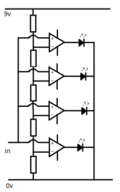
Say for example we have a series of op-amps.
the inverting leg of each amplifier is set to a different reference voltage, each a small distance apart.
now we connect the non-inverting legs together to form a single common input.
and we connect the outputs to a series of LEDs.


We now have a situation where:
starting at zero the state of each op amp is Vnon-inverting <= Vinverting, so all amplifiers are either  negative voltage, or zero volts at the output.
As the non-inverting input rises it will increase above the reference voltage applied to the non-inverting input of op-amp 1, this output will then go positive and the LED attached to it's output will turn on.
as the source rises further op-amp 2 will turn on.

We have created a level meter.

Notice that on this schematic the resistors that protect the LEDs are missing (because it's simpler that way)

So, in this circuit we're imagining that our input voltage swing between 0 and 8 volts

All the resistors are 1k,
so starting at the top and working down we know that the reference voltage applied to each function is

7.2v
5.4v
3.6v
1.8v

So when the source signal goes above 1.8v, the bottom LED will turn on,
when it goes above 3.6 the second from the bottom LED turns on.

But what id the signal is smaller?
Well, the reference voltage can be anything, if doesn't even have to have the same gap between the reference points.

You could have reference voltages of 0.1, 0.2, 0.5, 1 or anything you want.

You set your reference voltage with the resistor network.

Monday, April 16, 2012

Electronics lessons: Operational amplifiers

The last electronics lessons covered long tailed pairs, I talked about the best operation being gained when they were subject to the exact same environmental conditions, and to do this the transistors could be built on the same substrate of silicon.

Well enter Operational amplifiers, Op amps, comparators, op amp comparators.

they little guys seems to have many names, but they are the same thing, often the same part.
The reason that they have different names is the way in which they are used.

when investigating the long tailed pair we established that the output was (v1 - v2) x gain

The same is true for the operational amplifier.

Most operational amplifiers are extraordinarily high gain amplifiers, however we can use feedback to reign in that large gain.


So, to start with, let's look at the use for infinite gain differential amplifiers.

we talked about the long tailed pair and how the difference between v1 and v2 was amplifiers.

for example,
if v1 = 5 and v2 = 3, and the gain = 4
(5 - 3) * 4 = 8
The output would be 8.

the same is true of comparator amplifiers. except the gain is very very large
(5 - 3) * 1,000,000 = 2,000,000
except the output is not two million volts, because the supply to the circuit is only 12 volts, so the output will be 10 volts.

Yes, ten volts, the maximum output is supply rail voltage - 2 in most chips, (for example the LM741 chip)

This means that we can use the op-amp as a switch, comparing the voltage applied to v1 and v2, (positive and negative,/non-inverting and inverting, or pin 2 and pin3 in the case of the LM741)
where the switch will come on if the signal voltage applied to the non-inverting input goes above the reference voltage applied to the inverting input.

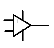
The circuit symbol is a triangle, this is (in black box block diagrams) the symbol for an amplifier, given that the op-amp is a hugely complex circuit packaged nicely in a black box, it seems fitting to use this symbol.


The pin outs are as follows, there are two inputs non-inverting (+) and inverting (-), the the output comes out of the point of the triangle, the two lines going into the top and the bottom are power lines, if there is only one power rail (no split rails) in the circuit then these may be omitted from a circuit design.

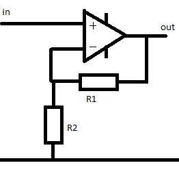
Non-inverting amplifier


We can reduce the gain of the amplifier using a network of resistors. when we made the common collector amplifier we made an inverting amplifier, that was when the signal to the base of the transistor was high, the transistor was in a state of conduction and the signal at the collector was low, (the same as the emitter)
When the signal at the base for the transistor fell the signal at the collector rose as the transistor stopped conducting allowing the supply voltage to exist at the output path.
that was an inverting amplifier.
input signal rise and output signal falling is inverted.

the non-inverting amplifier works in a way where when the input signal is rising the output signal is also rising.

the gain of this amplifier is
Av = 1 + R1/R2

if R1 = R2 then the gain is 2

1 + (50/50) = 2

if R1 = 10k and R2 = 5k

1 + 10k / 5k = 3

so for each 1 volt seen at the input, three volts will be seen at the output


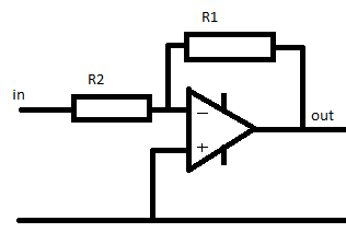
Inverting amplifier

The inverting amplifier is a little different.
(notice that the amplifier has been flipped upside down, and that the negative connection is at the top now.

the gain of this amplifier is
-R1/R2

So in this case if R1 = 10k and R2 = 5k the gain is
-10k/5k = -2

that doesn't mean that the signal is twice as small, it means that it's twice as big, but inverted.

for each 2volts seen at the input there will be 2 x -2 = -4 volts seen at the output

to reduce the signal you'd make R2 smaller than R1
e.g.
-5k / 10k  = -0.5
now for each 1 volt seen at the input there is -0.5 volts seen at the input.


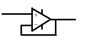
Unity gain amplifier

The unity gain amplifier does exactly what it says on the tin the output is at unity with the input, there is no gain.

So you might wonder what's the point.

Well. consider loading.

We know that power is equal to voltage times current, and that voltage is equal to current multiplied by resistance.

Realistically a microphone can supply fractions of volts, with fractions of watts of power.

We're talking in the realms of 0.1 volts (100 millivolts) and a power capability of something like 0.000001Watts


but to make the maths nice and easy, lets say that we have a 10 volt signal, that's capable of supplying 10 Watts

the maximum current available is 1 amp, (w/p = 10/10 = 1)

but what if we're trying to put this into a load of say 5 Ohms,

10 volts and 5 ohms, = 10/5 = 2amps drawn, but we aren't able to supply 2 amps, so the signal is going to be reduced, (the voltages will sag)
we're more likely to see around 7 volts, through that 5 ohm load which will draw out 1.4 amps ,(and 1.4 * 7 = 9.8watts roughly equal to our maximum power.

well a unity gain amplifier has an incredibly high input impedance.
now our 10 volt signal is looking at a 1million ohm load
10/1000000 = 0.00001amps, a tiny amount of power, which means that the signal is not loaded and does not sag.

in addition to this the unity gain amplifier as an incredibly low output impedance, meaning that you can drive very low ohm loads without the voltage getting loaded and sagging.

Monday, April 09, 2012

Coding lessons: Working with Files, (reading) (Lessons16)

Anyone following these lessons as actual lessons might think finally something useful.

After all everything we dealt with so far has concerned putting data into a system, working with that data and spitting it out, nothing has been saved at all  when the program completes running that's it, it closes and memory space used for the program that was containing any data goes back to the system where it's overwritten.

You might say to make a really useful program that you have to be able to store data, And of course you need to be able to open that file again, and possibly work with that data and save it in a slightly changed format.

So lets get right into it.

Ways of opening files
Files can be opened in a variety of ways, first and foremost the most basic way of opening a file is to open a file for reading only.

The second way of opening a file would be to open a file for writing, there are two ways of opening a file for writing.
open for overwriting, (where data will be added at the start of the file and overwrite existing data)
or open file for appending, (where data is added to the end of a file.

You select this mode of file opening by using r, w or a.

Files are opened by default in string mode. but files may also be opened in binary mode.


What this means is if you have a file that contains the decimal number 53, if you open this in string mode the number 5 will come out.
Decimal number 97 will be read as 'a' in string mode. (because that is the ASCII representation of the character)

If you have a file that is a series of numerical data then you should know that you want to open the file in binary mode to get your numerical data out.

to select to open the file in string mode, do nothing, (that's the default).
If you want to open the file in binary mode, add a b after the r/w/a file opening mode
if you want to open the file for both reading and writing add a + to the end.

for example if I want to open a file, read data, and then overwrite it, I open with the following mode operator

w+

if it's binary data I use

wb+

remember r opens the file for reading, and sets the file stream at the beginning of the file

w sets the file length to zero (and so overwrites) and points the file stream at the start of the file.

a, points the file stream to the end of the file, so that updates occur at the end of the file.


Reading files
when we access a file, just like when we access a memory resource we use a pointer to do it.

#include<stdio.h>
int main()
{
char c;
FILE *filepointer;


then we point our pointer at the file resource that we wish to access.

filepointer=fopen("D:\\coding\\lesson16\\file.txt", "r");


This is a file that contains a series of characters,
The file is a few characters long and then stops, you and I do not see the stop, but the end of the file is marked with a special marker called End Of File

while (c!=EOF)
{


so we say, while c, (which is the place we'll put characters as they are read from the file) is not the end of file marker, then do this (read the file)

c = getc(filepointer);

this says, c (the place where we're putting the characters read from the file) equals the result of the function getc(filepointer), getc is a function that says get the character pointed to by this pointer, the pointer is filepointer.

printf("%c", c);
}
fclose(filepointer);
}


Then we print the character and close the file

#include<stdio.>
int main()
{
int i=0;
char c;
FILE *filepointer;
filepointer=fopen("D:\\coding\\lesson16\\file.txt", "r");

while (c!=EOF)
{
i++;
c = getc(filepointer);
printf("%c", c);
}
printf("while loop ran %d times", i);
fclose(filepointer);
}


D:\coding\lesson16>source.exe
this
is
a
file! while loop ran 16 times
D:\coding\lesson16>

(and that is the contents of the file at the location.)
the file contains 16 characters
this(4) return(1) is(2) return(1) a(1) return(1) file!(5) return(1)

There are other ways of reading files,
in the same way as we get data from the keyboard using scanf, we can scan files using fscanf.

however, this time to make sure that we stop searching when we reach the end of the file we need to use the function feof(filepointer) to search for the end of the file.

when we use scanf we say scanf("datatype", &variable-to-store), when using fscanf we also need to include an argument to tell it what file to read data from, (in this way we can work with multiple file streams.

#include<stdio.h>
int main()
{
int i=0;
char string[50];
FILE *filepointer;
filepointer=fopen("D:\\coding\\lesson16\\file.txt", "r");

while (feof(filepointer)==0)
{
i++;
fscanf(filepointer, "%s", &string);
printf("%s", string);
}
printf("while loop ran %d times", i);
fclose(filepointer);
}


the loop runs four time, carriage returns are ignored, and there are 4 distinct inputs, in the same way we investigated the scanf statement and found that spaces are ignored, (when introducing flush() spaces are also ignored. so "Hello World" will appear as two strings.

and finally we can use fgets, earlier we used getc to read the file a single character at a time. now we're going to read the file as a string.

fgets requires us to provide three arguments
the charector array (string) in which the returned data will be stored.
the size chunk of data to bring back (number of characters)
the pointer to the file

#include<stdio.h>
int main()
{
int i=0;
char string[50];
FILE *filepointer;
filepointer=fopen("D:\\coding\\lesson16\\file.txt", "r");

while (feof(filepointer)==0)
{
i++;
fgets(string, 50, filepointer);
printf("%s", string);
}
printf("while loop ran %d times", i);
fclose(filepointer);
}


The loop runs 4 times. (as there are four strings)

if we had specified.
fgets(string, 3, filepointer);
then the loop runs 9 times

1, thi
2, s
3, [return]
4, is
5, [return]
6, a
7, [return]
8, fil
9, e!

Monday, April 02, 2012

Electronics lessons: Power supply

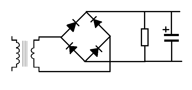
This is a very simple power supply circuit.
With the lessons on the transformer, diodes and capacitor this should be fairly self explanatory as to how this works, but I'll go through step by step.

What we need is to take a 240 volt supply an turn this into a 12 v supply for a circuit.

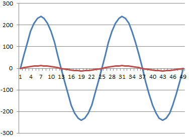
So we start with a transformer.

our mains voltage is 240, out ideal output voltage is 12

240/12 = 20, our transformer needs to be 20:1

After this we need to stop the voltage being an AC wave and rectify it.

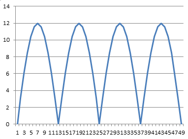
We'll use the full wave rectifier discussed earlier. this gives us that two humps per cycle (as the negative waveform becomes positive).

But this wave form isn't all that useful, you see each time it dips to zero it's effectively turning off.
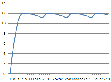
in order to smooth out the humps in the power supply we add a capacitor across the power rails, this acts like a battery storing power from the peaks of the humps and discharging, (and thus keeping the rail voltage high) as the hump drops to zero and whilst it's on it's way back up again.

Ripple Voltage
the series of humps has now been transformed into a straight DC line with a ripple in it.

That ripple can be very unwanted, consider what you can hear (20hz - 14Khz).
mains voltage is 50Hz, if you connected a speaker to the mains you would hear a low hum, (just before the fire started).

well, if the supply voltage in the circuit has a 50Hz ripple on it, that's also going to appear as hum at the output.

the ripple voltage is calculated as

Vpp = i/2fc where a full wave rectifier is used (as above)

Where a half wave rectifier is use it is Vpp = i/fc

So, where do we get the values from.

well,
vpp is the peak to peak value for the ripple voltage
I is the current in the circuits,
C is the value of the capacitor
and F is the frequency of the AC power

for the example above lets say that the load of the circuit is 1200Ohms.
we know that the votlage applied to that circuit is 12 volts

so the current is
12/1200 = 0.01A

The capacitor value is 0.001F (1 milifarfad)
and mains voltage is 50Hz

so the ripple voltage here is

vpp = 0.01/(50 * 0.001) = 0.2

so in this case the voltage goes between 11.8 and 12 volts, the ripple is 0.2 volts